MI VIF API
1. SCOPE
1.1. Module description
Video input (VIF) enables video input device, video input channel, binding video input channel and other functions.
1.2. Flow chart of Pretzel, Macaron, Pudding, Ispahan and Ikayaki

The Naboo series chips support Vif output port1, which is only used in BT656 interface, and the width/height of outport1 is half that of outport0.
The mapping between MI_Vif device and channel is as follows:

Pretzel and Pudding chip N max=3,
Macaron , Ispahan and Ikayaki chip N max=2
Note:N is Device Id.
Only the first channel in the corresponding vifdev can be used in Mipi interface, and multi channel in vifdev can be used in bt656 interface composite mode
2. API Reference
This function module provides the following API:
| API Name | Function |
|---|---|
| MI_VIF_SetDevAttr | Set VIF device attribute |
| MI_VIF_GetDevAttr | Get VIF device attribute |
| MI_VIF_EnableDev | Enable VIF device |
| MI_VIF_DisableDev | Disable VIF device |
| MI_VIF_SetChnPortAttr | Set VIF channel port attribute |
| MI_VIF_GetChnPortAttr | Get VIF channel port attribute |
| MI_VIF_EnableChnPort | Enable VIF channel port |
| MI_VIF_DisableChnPort | Disable VIF channel port |
| MI_VIF_Query | Query VIF channel port interrupt counts, average frame rate |
| MI_VIF_SetDev2SnrPadMux | Set VIF binding relation between device and sensor pad |
| MI_VIF_InitDev | Initialize VIF device |
| MI_VIF_DeInitDev | De-initialize VIF device |
| MI_VIF_GetDevStatus | Get the current status of VIF Dev |
| MI_VIF_CallBackTask_Register | Register callback interface with VIF |
| MI_VIF_CallBackTask_UnRegister | Unregister callback interface with VIF |
2.1. MI_VIF_SetDevAttr
-
Description
Set VIF device attribute.
-
Syntax
MI_S32 MI_VIF_SetDevAttr(MI_VIF_DEV u32VifDev,
MI_VIF_DevAttr_t *pstDevAttr)
-
Parameters
Parameter Name Description Input/Output u32VifDev VIF device number. Value range: [0, MI_VIF_MAX_DEV_NUM). Input pstDevAttr VIF device attribute pointer. Static attribute. Input -
Return Value
-
MI_SUCCESS(0): Successful
-
Non-zero: Failed, see error code for details
-
-
Dependence
-
header file: mi_vif_datatype.h, mi_vif.h
-
Library file: libmi_vif.a
-
-
Note
-
This API is available after VIF device is disabled using MI_VIF_DisableDev.
-
The parameter pstdevottr is mainly used to configure the video interface mode of the specified Vif device, which is used to interface with peripheral cameras and sensors. The supported interface modes include BT.656, digital camera and Mipi sensor. Please refer to Section 3.11 data type for specific attribute meanings.
-
-
Example
Example of Vif initialization start and exit:

STCHECKRESULT(MI_SNR_GetPadInfo(eSnrPadId, &stPad0Info)); STCHECKRESULT(MI_SNR_GetPlaneInfo(eSnrPadId, 0, &stSnrPlane0Info)); u32CapWidth = stSnrPlane0Info.stCapRect.u16Width; u32CapHeight = stSnrPlane0Info.stCapRect.u16Height; ePixFormat = (MI_SYS_PixelFormat_e)RGB_BAYER_PIXEL(stSnrPlane0Info.ePixPrecision, stSnrPlane0Info.eBayerId); /************************************************ init VIF *************************************************/ MI_VIF_DevAttr_t stDevAttr; MI_VIF_InitParam_t stInitParam; memset(&stDevAttr, 0x0, sizeof(MI_VIF_DevAttr_t)); memset(&stInitParam, 0x0, sizeof(MI_VIF_InitParam_t)); stInitParam.u32DevId = 0; stInitParam.u8Data = 0; STCHECKRESULT(MI_VIF_InitDev(&stInitParam)); stDevAttr.eIntfMode = stPad0Info.eIntfMode; stDevAttr.eWorkMode = pstVifDevAttr->eWorkMode; stDevAttr.eHDRType = (MI_VIF_HDRType_e)pstVpeChnattr->eHdrType; if(stDevAttr.eIntfMode == E_MI_VIF_MODE_BT656) stDevAttr.eClkEdge = stPad0Info.unIntfAttr.stBt656Attr.eClkEdge; else stDevAttr.eClkEdge = E_MI_VIF_CLK_EDGE_DOUBLE; if(stDevAttr.eIntfMode == E_MI_VIF_MODE_MIPI) stDevAttr.eDataSeq =stPad0Info.unIntfAttr.stMipiAttr.eDataYUVOrder; else stDevAttr.eDataSeq = E_MI_VIF_INPUT_DATA_YUYV; if(stDevAttr.eIntfMode == E_MI_VIF_MODE_BT656) memcpy(&stDevAttr.stSyncAttr, &stPad0Info.unIntfAttr.stBt656Attr.stSyncAttr, sizeof(MI_VIF_SyncAttr_t)); stDevAttr.eBitOrder = E_MI_VIF_BITORDER_NORMAL; STCHECKRESULT(MI_VIF_SetDevAttr(vifDev, &stDevAttr)); STCHECKRESULT(MI_VIF_EnableDev(vifDev)); MI_VIF_ChnPortAttr_t stVifPortInfo; memset(&stVifPortInfo, 0, sizeof(MI_VIF_ChnPortAttr_t)); stVifPortInfo.stCapRect.u16X = stSnrPlane0Info.stCapRect.u16X; stVifPortInfo.stCapRect.u16Y = stSnrPlane0Info.stCapRect.u16Y; stVifPortInfo.stCapRect.u16Width = stSnrPlane0Info.stCapRect.u16Width; stVifPortInfo.stCapRect.u16Height = stSnrPlane0Info.stCapRect.u16Height; stVifPortInfo.stDestSize.u16Width = u32CapWidth; stVifPortInfo.stDestSize.u16Height = u32CapHeight; stVifPortInfo.ePixFormat = ePixFormat; //stVifPortInfo.u32FrameModeLineCount for lowlantancy mode if(stDevAttr.eIntfMode == E_MI_VIF_MODE_BT656) { stVifPortInfo.eFrameRate = E_MI_VIF_FRAMERATE_FULL; stVifPortInfo.eCapSel = E_MI_SYS_FIELDTYPE_BOTH; stVifPortInfo.eScanMode = E_MI_SYS_FRAME_SCAN_MODE_PROGRESSIVE; } STCHECKRESULT(MI_VIF_SetChnPortAttr(vifChn, vifPort, &stVifPortInfo)); STCHECKRESULT(MI_VIF_EnableChnPort(vifChn, vifPort)); /************************************************ call sys bind interface *************************************************/ /************************************************ exit call sys unbind interface *************************************************/ STCHECKRESULT(MI_VIF_DisableChnPort(vifChn, vifPort)); STCHECKRESULT(MI_VIF_DisableDev(vifDev)); STCHECKRESULT(MI_VIF_DeInitDev()); -
Related APIs
2.2. MI_VIF_GetDevAttr
-
Description
Get VIF device attribute.
-
Syntax
MI_S32 MI_VIF_GetDevAttr(MI_VIF_DEV u32VifDev,
MI_VIF_DevAttr_t *pstDevAttr)
-
Parameters
Parameter Name Description Input/Output u32VifDev VIF device number. Value range: [0, MI_VIF_MAX_DEV_NUM). Note: devid of VIF must be set by 0 during binding Input pstDevAttr VIF device attribute pointer. Output -
Return Value
-
MI_SUCCESS(0): Successful
-
Non-zero: Failed, see error code for details
-
-
Dependence
-
header file: mi_vif_datatype.h, mi_vif.h
-
Library file: libmi_vif.a
-
-
Note
This API will return fail if VIF device attribute is not configured
-
Related APIs
2.3. MI_VIF_EnableDev
-
Description
Enable VIF device.
-
Syntax
MI_S32 MI_VIF_EnableDev(MI_VIF_DEV u32VifDev);
-
Parameters
Parameter Name Description Input/Output u32VifDev VIF device number. Input -
Return Value
-
MI_SUCCESS(0): Successful
-
Non-zero: Failed, see error code for details
-
-
Dependence
-
header file: mi_vif_datatype.h, mi_vif.h
-
Library file: libmi_vif.a
-
-
Note
-
Enable must be after device attribute have be configured, or fail will be returned
-
Calling again is available, fail will not be returned.
-
-
Example
Please refer to MI_VIF_SetDevAttr.
-
Related APIs
2.4. MI_VIF_DisableDev
-
Description
Disable VIF device.
-
Syntax
MI_S32 MI_VIF_DisableDev(MI_VIF_DEV u32VifDev);
-
Parameters
Parameter Name Description Input/Output u32VifDev VIF device number. Input -
Return Value
-
MI_SUCCESS(0): Successful
-
Non-zero: Failed, see error code for details
-
-
Dependence
-
header file: mi_vif_datatype.h, mi_vif.h
-
Library file: libmi_vif.a
-
-
Note
-
Disable of VIF device is available after all binding channels of VIF have be disabled
-
Calling again is available, fail will not be returned.
-
-
Example
Please refer to MI_VIF_SetDevAttr.
-
Related APIs
2.5. MI_VIF_SetChnPortAttr
-
Description
Set VIF channel port attribute.
-
Syntax
MI_S32 MI_VIF_SetChnPortAttr(MI_VIF_CHN u32VifChn, MI_VIF_PORT
u32ChnPort, MI_VIF_ChnPortAttr_t *pstAttr);
-
Parameters
Parameter Name Description Input/Output u32VifChn VIF channel number. Input u32ChnPort Port number Input pstAttr VIF channel Port attribute pointer. Input -
Return Value
-
MI_SUCCESS(0): Successful
-
Non-zero: Failed, see error code for details
-
-
Dependence
-
header file: mi_vif_datatype.h, mi_vif.h
-
Library file: libmi_vif.a
-
-
Note
The purpose to use MI_VIF_SetChnPortAttr is to set port attributes like CapSize, DestSize, FrameRate.
-
Example
Please refer to MI_VIF_SetDevAttr.
-
Related APIs
2.6. MI_VIF_GetChnPortAttr
-
Description
Get VIF channel port attribute.
-
Syntax
MI_S32 MI_VIF_GetChnPortAttr(MI_VIF_CHN u32VifChn, MI_VIF_PORT
u32ChnPort, MI_VIF_ChnPortAttr_t *pstAttr);
-
Parameters
Parameter Name Description Input/Output u32VifChn VIF channel number. Value range: [0, MI_VIF_MAX_PHYCHN_NUM). Input u32ChnPort Port number Input pstAttr VIF channel port attribute pointer. Dynamic attribute. Output -
Return Value
-
MI_SUCCESS(0): Successful
-
Non-zero: Failed, see error code for details
-
-
Dependence
-
header file: mi_vif_datatype.h, mi_vif.h
-
Library file: libmi_vif.a
-
-
Note
Getting must be after setting.
-
Example
Please refer to MI_VIF_SetChnPortAttr.
-
Related APIs
2.7. MI_VIF_EnableChnPort
-
Description
Enable VIF channel port.
-
Syntax
MI_S32 MI_VIF_EnableChnPort (MI_VIF_CHN u32VifChn, MI_VIF_PORT
u32ChnPort);
-
Parameters
Parameter Name Description Input/Output VifChn VIF channel number. Input -
Return Value
-
MI_SUCCESS(0): Successful
-
Non-zero: Failed, see error code for details
-
-
Dependence
-
header file: mi_vif_datatype.h, mi_vif.h
-
Library file: libmi_vif.a
-
-
Note
-
Channel attribute must be configured first, VIF device bound with channel must be enabled
-
If VIF and DISP/VENC are bound, calling of this API can get video
-
Calling again to enable VIF channel is available, fail will not be returned.
-
-
Example
Please refer to MI_VIF_SetDevAttr.
-
Related APIs
2.8. MI_VIF_DisableChnPort
-
Description
Disable VIF channel port.
-
Syntax
MI_S32 MI_VIF_DisableChnPort (MI_VIF_CHN u32VifChn, MI_VIF_PORT
u32ChnPort);
-
Parameters
Parameter Name Description Input/Output u32VifChn VIF channel number. Input u32ChnPort Port number Input -
Return Value
-
MI_SUCCESS(0): Successful
-
Non-zero: Failed, see error code for details
-
-
Dependence
-
header file: mi_vif_datatype.h, mi_vif.h
-
Library file: libmi_vif.a
-
-
Note
-
After disabling of VIF channel port, this VIF channel port will stop get video, and VO and VENC bound will stop get video as well
-
Calling again to disable VIF channel is available, fail will not be returned.
-
-
Example
Please refer to MI_VIF_SetDevAttr.
-
Related APIs
2.9. MI_VIF_Query
-
Description
Query VIF channel port interrupt counts, average frame rate….
-
Syntax
MI_S32 MI_VIF_Query(MI_VIF_CHN u32VifChn, MI_VIF_PORT u32ChnPort,
MI_VIF_ChnPortStat_t *pstStat);
-
Parameters
Parameter Name Description Input/Output u32VifChn VIF channel number. Input u32ChnPort Channel Port Input pstStat Channel information structure pointer. Output -
Return Value
-
MI_SUCCESS(0): Successful
-
Non-zero: Failed, see error code for details
-
-
Dependence
-
header file: mi_vif_datatype.h, mi_vif.h
-
Library file: libmi_vif.a
-
-
Note
-
This API can be used to query interrupt counts, channel enable/disable status, interrupt loss counts, VB fail counts, height/width of image.
-
Frame rate got via this API is average frame rate over 1 second, VIF could calculate average frame rate every second, the precision of this value is not exact.
-
User could query interrupt loss counts via this API. If this loss counts increase at all time, it meant VIF is abnormal.
-
This interface is temporarily not supported.
-
2.10. MI_VIF_SetDev2SnrPadMux
-
Description
Set VIF binding relation between device and sensor pad
-
Syntax
MI_S32 MI_VIF_SetDev2SnrPadMux(MI_VIF_Dev2SnrPadMuxCfg_t
stVifDevMap[], MI_U8 u8Length);
-
Parameters
Parameter Name Description Input/Output stVifDevMap Mapping relation between Dev and SensorPad Input u8Length Dev Num Input -
Return Value
-
MI_SUCCESS(0): Successful
-
Non-zero: Failed, see error code for details
-
-
Dependence
-
header file: mi_vif_datatype.h, mi_vif.h
-
Library file: libmi_vif.a
-
-
Note
-
In default, mapping relation between vif Dev and SensorPad is vif Dev0 -> SensorPad0, vif Dev2 -> SensorPad1. If you want to use other Vif Dev or Sensor Pad, you need to set the corresponding connection relationship with MI_VIF_SetDev2SnrPadMux api.
-
The VIF DEV and SENOSRPAD correspondence is reset to default after MI_SNR_SetPlaneMode, so MI_VIF_SetDev2SnrPadMux should be called after MI_SNR_SetPlaneMode.
-
-
Example
Vif Dev0 binds SensorPad0, Dev1 binds SensorPad2, Dev2 binds SensorPad1,An example of binding relationship is as follows:
MI_VIF_Dev2SnrPadMuxCfg_t stVifDev[4];

stVifDev[0].eSensorPadID = E_MI_VIF_SNRPAD_ID_0;

stVifDev[0].u32PlaneID = 0xff;//oxff liner mode, 0: Long exposure, 1: Short
exposure

stVifDev[1].eSensorPadID = E_MI_VIF_SNRPAD_ID_2;

stVifDev[1].u32PlaneID = 0xff;

stVifDev[2].eSensorPadID = E_MI_VIF_SNRPAD_ID_1;

stVifDev[2].u32PlaneID = 0xff;

stVifDev[3].eSensorPadID = E_MI_VIF_SNRPAD_ID_3;

stVifDev[3].u32PlaneID = 0xff;

MI_VIF_SetDev2SnrPadMux(stVifDev, 4);
2.11. MI_VIF_InitDev
-
Description
Initialize VIF device.
-
Syntax
MI_S32 MI_VIF_InitDev(MI_VIF_InitParam_t *pstInitParam);
-
Parameters
Parameter Description Input/Output pstInitParam Initialization Parameter Input -
Return value
-
MI_SUCCESS(0): Successful
-
Non-zero: Failed, see error code for details
-
-
Dependency
-
header file: mi_common.h, mi_vif.h
-
Library file: libmi_vif.a
-
-
note
This interface is called when STR takes effect. If STR is invalid and the default initialization parameters are in use, this interface will not be called.
-
Example
Please refer to MI_VIF_SetDevAttr.
2.12. MI_VIF_DeInitDev
-
Description
De-initialize VIF device.
-
Syntax
MI_S32 MI_VIF_DeInitDev(void);
-
Return value
-
MI_SUCCESS(0): Successful
-
Non-zero: Failed, see error code for details
-
-
Dependency
-
header file: mi_common.h, mi_vif.h
-
Library file: libmi_vif.a
-
-
Note
- This interface is called only when STR takes effect.
- This interface must be called after the VPE channel is destroyed, otherwise it will return MI_ERR_FAILED.
- If the interface is called repeatedly, it will report fd is Invalid and return MI_ERR_FAILED.
-
Example
Please refer to MI_VIF_SetDevAttr
2.13. MI_VIF_GetDevStatus
-
Description
Get the current status of VIF Dev
-
Syntax
MI_S32 MI_VIF_IMPL_GetDevStatus(MI_VIF_DEV
u32Vifdev, MI_VIF_DevStatus_t *pstVifDevStatus);
-
Parameters
Parameter Description Input/Output u32Vifdev VIF Dev ID Input pstVifDevStatus VIF Dev current status Output -
Return value
-
MI_SUCCESS(0): Successful
-
Non-zero: Failed, see error code for details
-
-
Dependency
-
header file: mi_vif_datatype.h、mi_vif.h
-
Library file: libmi_vif.a
-
-
Example
The API realizes Get VIF Dev current status,Use examples are as follows.
MI_VIF_DevStatus_t stVifDev[VIF_MAX_DEV_NUM];

MI_VIF_DEV a = 0;

for(a=0;a< VIF_MAX_DEV_NUM;a++)

{

    ret = MI_VIF_GetDevStatus(a,&stVifDev[a]);

}
2.14. MI_VIF_CallBackTask_Register
-
Description
Register callback interface with VIF
-
Syntax
MI_S32 MI_VIF_CallBackTask_Register(MI_VIF_CHN u32VifChn,
MI_VIF_CallBackParam_t *pstCallBackParam);
-
Parameters
Parameter Name Description Input/Output u32VifChn VIF Chn ID Input pstCallBackParam Arguments Input -
Return value
-
MI_SUCCESS(0): Successful
-
Non-zero: Failed, see error code for details
-
-
Dependency
-
Header file:mi_common.h、mi_vif.h
-
Library file:libmi_vif.a
-
-
Note
-
Currently, this interface only supports kernel mode calls
-
This interface must be called in pair with MI_VIF_CallBackTask_UnRegister
-
-
Example
MI_S32 _mi_vif_framestart1(MI_U64 u64Data) { DBG_ERR("DATA %llu \n", u64Data); return 0; } MI_S32 _mi_vif_framestart2(MI_U64 u64Data) { DBG_ERR("DATA %llu \n", u64Data); return 0; } static MS_S32 _mi_vif_testRegVifCallback(void) { MI_VIF_CallBackParam_t stCallBackParam1; MI_VIF_CallBackParam_t stCallBackParam2; MI_VIF_CHN u32VifChn = 0; memset(&stCallBackParam1, 0x0, sizeof(MI_VIF_CallBackParam_t)); memset(&stCallBackParam2, 0x0, sizeof(MI_VIF_CallBackParam_t)); stCallBackParam1.eCallBackMode = E_MI_VIF_CALLBACK_ISR; stCallBackParam1.eIrqType = E_MI_VIF_IRQ_FRAMESTART; stCallBackParam1.pfnCallBackFunc = _mi_vif_framestart1; stCallBackParam1.u64Data = 11; MI_VIF_CallBackTask_Register(u32VifChn,&stCallBackParam1); stCallBackParam2.eCallBackMode = E_MI_VIF_CALLBACK_ISR; stCallBackParam2.eIrqType = E_MI_VIF_IRQ_FRAMESTART; stCallBackParam2.pfnCallBackFunc = _mi_vif_framestart2; stCallBackParam2.u64Data = 22; MI_VIF_CallBackTask_Register(u32VifChn,&stCallBackParam2); return 0; } static MS_S32 _mi_vif_testUnRegVifCallback(void) { MI_VIF_CallBackParam_t stCallBackParam1; MI_VIF_CallBackParam_t stCallBackParam2; MI_VIF_CHN u32VifChn = 0; memset(&stCallBackParam1, 0x0, sizeof(MI_VIF_CallBackParam_t)); memset(&stCallBackParam1, 0x0, sizeof(MI_VIF_CallBackParam_t)); stCallBackParam1.eCallBackMode = E_MI_VIF_CALLBACK_ISR; stCallBackParam1.eIrqType = E_MI_VIF_IRQ_FRAMESTART; stCallBackParam1.pfnCallBackFunc = _mi_vif_framestart1; stCallBackParam1.u64Data = 33; MI_VIF_CallBackTask_UnRegister(u32VifChn,&stCallBackParam1); stCallBackParam2.eCallBackMode = E_MI_VIF_CALLBACK_ISR; stCallBackParam2.eIrqType = E_MI_VIF_IRQ_FRAMESTART; stCallBackParam2.pfnCallBackFunc = _mi_vif_framestart2; stCallBackParam2.u64Data = 44; MI_VIF_CallBackTask_UnRegister(u32VifChn,&stCallBackParam2); return 0; } -
Related topic
2.15. MI_VIF_CallBackTask_UnRegister
-
Description
Unregister callback interface with VIF
-
Syntax
MI_S32 MI_VIF_CallBackTask_UnRegister(MI_VIF_CHN u32VifChn,
MI_VIF_CallBackParam_t *pstCallBackParam);
-
Parameters
Parameter Name Description Input/Output u32VifChn VIF Chn ID Input pstCallBackParam Arguments Input -
Return value
-
MI_SUCCESS(0): Successful
-
Non-zero: Failed, see error code for details
-
-
Dependency
-
Header file:mi_common.h、mi_vif.h
-
Library file:libmi_vif.a
-
-
Note
-
Currently, this interface only supports kernel mode calls
-
This interface must be called in pair with MI_VIF_CallBackTask_Register
-
-
Example
Refer to MI_VIF_CallBackTask_Register example.
-
Related topic
3. VIF data type
VIF module relative data type definition:
| Data type | Description |
|---|---|
| MI_VIF_IntfMode_e | Define interface mode of video Input device |
| MI_VIF_WorkMode_e | Define working mode of video Input device |
| MI_VIF_FrameRate_e | Define relation between Output fps and Input fps |
| MI_VIF_DataYuvSeq_e | Define YUV data sequence received from video Input device |
| MI_VIF_ClkEdge_e | Define clock edge received from video Input device |
| MI_VIF_BitOrder_e | Define data bit order of video Input device |
| MI_VIF_HDRType_e | Define HDR type of video Input device |
| MI_VIF_Polar_e | Define signal polarity |
| MI_VIF_DevId_e | Define the ID of the video device |
| MI_VIF_SyncAttr_t | Define synchronization attribute |
| MI_VIF_DevAttr_t | Define attribute of video Input device. |
| MI_VIF_ChnPortAttr_t | Define VIF channel port attribute. |
| MI_VIF_ChnPortStat_t | Define VIF channel port status |
| MI_VIF_SNRPad_e | Define SensorPad Id |
| MI_VIF_Dev2SnrPadMuxCfg_t | Define binding relation between VIF device and SensorPad |
| MI_VIF_InitParam_t | Define the initialized parameter of VIF device |
| MI_VIF_DevStatus_t | Define VIF device current status |
| MI_VIF_CALLBK_FUNC | Define callback function type |
| MI_VIF_CallBackMode_e | Define callback mode |
| MI_VIF_IrqType_e | Define hardware interrupt type |
| MI_VIF_CallBackParam_t | Define callback parameters |
3.1. MI_VIF_IntfMode_e
-
Description
Define interface mode of video Input device
-
Definition
typedef enum { E_MI_VIF_MODE_BT656 = 0, E_MI_VIF_MODE_DIGITAL_CAMERA, E_MI_VIF_MODE_BT1120_STANDARD, E_MI_VIF_MODE_BT1120_INTERLEAVED, E_MI_VIF_MODE_MIPI, E_MI_VIF_MODE_BT601, E_MI_VIF_MODE_NUM } MI_VIF_IntfMode_e; -
member
Member name Description E_MI_VIF_MODE_BT656 Input data protocol is standard BT.656, port data Input mode is compound mode of brightness and color, quantity mode is single E_MI_VIF_MODE_DIGITAL_CAMERA Input data protocol is Digital camera 6, port data Input mode is compound mode of brightness and color, quantity mode is single E_MI_VIF_MODE_BT1120_STANDARD Input data protocol is standard BT.1120(BT.656+ double quantity), port data Input mode is division mode of brightness and color, quantity mode is double E_MI_VIF_MODE_BT1120_INTERLEAVED Input data protocol is BT.1120 interleave mode, port data Input mode is division mode of brightness and color, quantity mode is double E_MI_VIF_MODE_MIPI Input data protocol is MIPI E_MI_VIF_MODE_BT601 Input data protocol is BT.601 -
Note
The current interface mode can be obtained from eintfmode in MI_SNR_GetPadInfo.
-
Related Type
3.2. MI_VIF_WorkMode_e
-
Description
Define working mode of video Input device
-
Definition
typedef enum { /* BT656 multiple ch mode */ E_MI_VIF_WORK_MODE_1MULTIPLEX, E_MI_VIF_WORK_MODE_2MULTIPLEX, E_MI_VIF_WORK_MODE_4MULTIPLEX, /* RGB mode for MIPI/Parallel sensor */ E_MI_VIF_WORK_MODE_RGB_REALTIME, E_MI_VIF_WORK_MODE_RGB_FRAMEMODE, E_MI_VIF_WORK_MODE_MAX } MI_VIF_WorkMode_e; -
member
Member name Description E_MI_VIF_WORK_MODE_1MULTIPLEX 1 way compound working mode. E_MI_VIF_WORK_MODE_2MULTIPLEX 2 way compound working mode, Input data protocol must be standard BT.656. E_MI_VIF_WORK_MODE_4MULTIPLEX 4 way compound working mode, Input data protocol must be standard BT.656. E_MI_VIF_WORK_MODE_RGB_REALTIME RGB Realtime mode for MIPI/Parallel sensor E_MI_VIF_WORK_MODE_RGB_FRAMEMODE RGB Framemode mode for MIPI/Parallel sensor -
Note
-
When this item is set to RGB_realtime, the backend can only bind MI_VPE module, and MI_VPE should also be set to realtime mode. There is no DRAM buffer between the two modules, the underlying hardware is directly connected. When this item is set to RGB_realtime, the two modules do not support time-sharing multiplexing.
-
When this item is set to RGB frame, Vif writes buffer to the DRAM and sends it to the back-end module
-
The Pudding and Ispahan series chips do not support multiplex WorkMode, which is invalid when WorkMode is set to multiplex WorkMode. When using BT656 sensors, WorkMode needs to be set to RGB_REALTIME or RGB_FRAME.
-
-
Related Type
3.3. MI_VIF_FrameRate_e
-
Description
Define relation between Output fps and Input fps.
-
Definition
typedef enum { E_MI_VIF_FRAMERATE_FULL = 0, E_MI_VIF_FRAMERATE_HALF, E_MI_VIF_FRAMERATE_QUARTR, E_MI_VIF_FRAMERATE_OCTANT, E_MI_VIF_FRAMERATE_THREE_QUARTERS, E_MI_VIF_FRAMERATE_NUM, } MI_VIF_FrameRate_e; -
member
Member name Description E_MI_VIF_FRAMERATE_FULL Source over target is 1:1 Output. E_MI_VIF_FRAMERATE_HALF Source over target is 2:1 Output. E_MI_VIF_FRAMERATE_QUARTER Source over target is 4:1 Output. E_MI_VIF_FRAMERATE_OCTANT Source over target is 8:1 Output. E_MI_VIF_FRAMERATE_THREE_QUARTERS Source over target is 4:3 Output. -
Note
It’s available just in BT656 multiple channel mode.
-
Related Type
3.4. MI_VIF_DataYuvSeq_e
-
Description
Define YUV data sequence received from video Input device
-
Definition
typedef enum { E_MI_VIF_INPUT_DATA_VUVU = 0, E_MI_VIF_INPUT_DATA_UVUV, E_MI_VIF_INPUT_DATA_UYVY = 0, E_MI_VIF_INPUT_DATA_VYUY, E_MI_VIF_INPUT_DATA_YUYV, E_MI_VIF_INPUT_DATA_YVYU, E_MI_VIF_DATA_YUV_NUM } MI_VIF_DataYuvSeq_e; -
member
Member name Description E_MI_VIF_INPUT_DATA_VUVU YUV data Input via division mode, C quantity Input sequence is VUVU. E_MI_VIF_INPUT_DATA_UVUV YUV data Input via division mode, C quantity Input sequence is UVUV. E_MI_VIF_INPUT_DATA_UYVY YUV data Input via compound mode, sequence is UYVY. E_MI_VIF_INPUT_DATA_VYUY YUV data Input via compound mode, sequence is VYUY. E_MI_VIF_INPUT_DATA_YUYV YUV data Input via compound mode, sequence is YUYV. E_MI_VIF_INPUT_DATA_YVYU YUV data Input via compound mode, sequence is YVYU. -
Related Type
3.5. MI_VIF_ClkEdge_e
-
Description
Define clock edge received from video Input device
-
Definition
typedef enum { E_MI_VIF_CLK_EDGE_SINGLE_UP = 0, E_MI_VIF_CLK_EDGE_SINGLE_DOWN, E_MI_VIF_CLK_EDGE_DOUBLE, E_MI_VIF_CLK_EDGE_NUM } MI_VIF_ClkEdge_e; -
member
Member name Description E_MI_VIF_CLK_EDGE_SINGLE_UP Clock single edge mode, sampling in up edge E_MI_VIF_CLK_EDGE_SINGLE_DOWN lock single edge mode, sampling in down edge E_MI_VIF_CLK_EDGE_DOUBLE VIF do sampling in double edge for double edge data -
Related Type
3.6. MI_VIF_BitOrder_e
-
Description
Define data bit order of video Input device
-
Definition
typedef enum { E_MI_VIF_BITORDER_NORMAL = 0, E_MI_VIF_BITORDER_REVERSED } MI_VIF_BitOrder_e; -
member
Member name Description E_MI_VIF_BITORDER_NORMAL Normal data bit order E_MI_VIF_BITORDER_REVERSED Reversed data bit order -
Related Type
3.7. MI_VIF_HDRType_e
-
Description
Define HDR type of video Input device
-
Definition
typedef enum { E_MI_VIF_HDR_TYPE_OFF, E_MI_VIF_HDR_TYPE_VC, //virtual channel mode HDR,vc0->long, vc1->short E_MI_VIF_HDR_TYPE_DOL, E_MI_VIF_HDR_TYPE_EMBEDDED, //compressed HDR mode E_MI_VIF_HDR_TYPE_LI, //Line interlace HDR E_MI_VIF_HDR_TYPE_MAX } MI_VIF_HDRType_e; -
member
Member name Description E_MI_VIF_HDR_TYPE_OFF HDR off E_MI_VIF_HDR_TYPE_VC virtual channel mode HDR,vc0->long, vc1->short E_MI_VIF_HDR_TYPE_DOL Digital Overlap High Dynamic Range E_MI_VIF_HDR_TYPE_EMBEDDED compressed HDR mode E_MI_VIF_HDR_TYPE_LI Line interlace HDR -
Note
-
HDR type is related to the sensor. You can obtain the HDR type supported by the current sensor through ehdrmode of MI_SNR_GetPadInfo.
-
The realization of HDR function requires MI_VIF and MI_VPE modules to set the same HDR type.
-
-
Related Type
3.8. MI_VIF_Polar_e
-
Description
Define signal polarity
-
Definition
typedef enum { E_MI_VIF_PIN_POLAR_POS, E_MI_VIF_PIN_POLAR_NEG } MI_VIF_Polar_e; -
member
Member name Description E_MI_VIF_PIN_POLAR_POS High level active E_MI_VIF_PIN_POLAR_NEG Log level active -
Note
Available only for parallel sensor interface
-
Related Type
3.9. MI_VIF_DevId_e
-
Description
Define the ID of the video device
-
Definition
typedef enum { E_MI_VIF_DEVICE_ID0 = 0x0001, E_MI_VIF_DEVICE_ID1 = 0x0002, E_MI_VIF_DEVICE_ID2 = 0x0004, E_MI_VIF_DEVICE_ID3 = 0x0008, E_MI_VIF_DEVICE_ID4 = 0x0010, E_MI_VIF_DEVICE_ID5 = 0x0020, E_MI_VIF_DEVICE_ID6 = 0x0040, E_MI_VIF_DEVICE_ID7 = 0x0080, E_MI_VIF_DEVICE_ID8 = 0x0100, E_MI_VIF_DEVICE_ID9 = 0x0200, E_MI_VIF_DEVICE_ID10 = 0x0400, E_MI_VIF_DEVICE_ID11 = 0x0800, E_MI_VIF_DEVICE_ID12 = 0x1000, E_MI_VIF_DEVICE_ID13 = 0x2000, E_MI_VIF_DEVICE_ID14 = 0x4000, E_MI_VIF_DEVICE_ID15 = 0x8000, E_MI_VIF_DEVICE_ID_MAX = 0xffff } MI_VIF_DevId_e; -
Related Type
3.10. MI_VIF_SyncAttr_t
-
Description
Define synchronization attribute
-
Definition
typedef struct MI_VIF_SyncAttr_s { MI_VIF_Polar_e eVsyncPolarity; MI_VIF_Polar_e eHsyncPolarity; MI_VIF_Polar_e ePclkPolarity; MI_U32 VsyncDelay; MI_U32 HsyncDelay; MI_U32 PclkDelay; } MI_VIF_SyncAttr_t; -
member
Member name Description eVsyncPolarity V sync. effective polarity eHsyncPolarity H sync. effective polarity ePclkPolarity Pixel Clock effective polarity VsyncDelay V sync. delay time HsyncDelay H sync. delay time PclkDelay Pixel Clock delay time At 1920x1080 resolution, PCLK / Hsync / Vsync are all high-level effective, and the waveform corresponding relationship is as follows:

Pclk: pixel clock, Every time a pixel is received, a clock is generated.
Hsync: Line synchronization, when valid, the received signal belongs to the same line.
Vsync: Field synchronization, when valid, the received signal belongs to the same frame.
-
Note
only for parallel sensor interface
-
Related Type
3.11. MI_VIF_DevAttr_t
-
Description
Define attribute of video Input device.
-
Definition
typedef struct MI_VIF_DevAttr_s { MI_VIF_IntfMode_e eIntfMode; MI_VIF_WorkMode_e eWorkMode; MI_VIF_HDRType_e eHDRType; MI_VIF_ClkEdge_e eClkEdge; MI_VIF_DataYuvSeq_e eDataSeq; MI_VIF_BitOrder_e eBitOrder; /* adjust bit order layout */ MI_VIF_SyncAttr_t stSyncAttr; MI_U32 u32DevStitchMask; //multi vif dev bitmask by MI_VIF_DevId_e } MI_VIF_DevAttr_t; -
member
Member name Description eIntfMode Interface mode. eWorkMode Working mode. eHDRType HDR type eClkEdge Clock edge mode (up sampling, down sampling, double sapling). eDataSeq Input data sequence (only support yuv), need to configure for Digital Camera mode, invalid for other modes. eBitOrder Vif data layout bit order stSyncAttr Synchronization attribute u32DevStitchMask Image fusion device ID -
Note
u32DevStitchMask = E_MI_VIF_DEVICE_ID0| E_MI_VIF_DEVICE_ID2 When this parameter is set, the backend MI_VPE must use MI_VPE_ Createmultichannelstitch API to create channels. For details, please refer to the example provided in the MI_VPE API document with regard to said API.
-
Related Type
3.12. MI_VIF_ChnPortAttr_t
-
Description
Define VIF channel port attribute.
-
Definition
typedef struct MI_VI_ChnPortAttr_s { MI_SYS_WindowRect_t stCapRect; MI_SYS_WindowRect_t stDestSize; MI_SYS_FieldType_e enCapSel; MI_SYS_FrameScanMode_e nScanMode; MI_SYS_PixelFormat_e ePixFormat; MI_VI_FrameRate_e eFrameRate; MI_U32 u32FrameModeLineCount } MI_VI_ChnPortAttr_t; -
member
sub ports only support stDestSize, enDstFrameRate, other attributes will be ignored.
Member name Description stCapRect coordinates and width and height of capturing region(based on original device image) stDestSize destination image size. Must to be configured, the size cannot over outside ADC Input image, or VIF hardware may be abnormal eCapSel capturing frame selection for line-over mode, suggest capture bottom field when capturing of single field. Must to set E_MI_SYS_FIELDTYPE_BOTH for each line-each mode. eScanMode Input scan mode (line-each, line-over) ePixFormat Supported Pixel format. eFrameRate Ratio of target fps over Input fps. Set 0 to ignore fps control. Output with 1:1,2:1,4:1,8:1,4:3 u32FrameModeLineCount Inform next stage about the processing moment , use with E_MI_VIF_WORK_MODE_RGB_FRAMEMODE -
chip difference
Member name Description stDestSize VIF channel is able to scale, horizontal scaling down 2 multiple, vertical scaling down 2 multiple. -
Related Type
3.13. MI_VIF_ChnPortStat_t
-
Description
Define VIF channel port status
-
Definition
typedef struct MI_VIF_ChnStat_s { MI_BOOL bEnable; /* Whether this channel is enabled */ MI_U32 u32IntCnt; /* The VIFdeo frame interrupt count */ MI_U32 u32FrmRate; /* current frame rate */ MI_U32 u32LostInt; /* The interrupt is received but nobody care */ MI_U32 u32VbFail; /* Video buffer malloc failure */ MI_U32 u32PicWidth;/* curren pic width */ MI_U32 u32PicHeight;/* current pic height */ } MI_VIF_ChnPortStat_t; -
member
Member name Description bEnable Channel enable. u32IntCnt Interrupt count. u32FrmRate Average fps every 1s, the precision is not perfect. u32LostInt Interrupt loss count. u32VbFail VB fail count. u32PicWidth Picture width. u32PicHeight Picture heigh. -
Note
-
Interrupt count can be used to detect no interrupt
-
Fps is average fps every 1s, VIF calculate average fps every 1s, the precision is not perfect.
-
If interrupt loss count increased all the time, it meant VIF is abnormal
-
3.14. MI_VIF_SNRPad_e
-
Description
Define SensorPad Id
-
Definition
typedef enum { E_MI_VIF_SNRPAD_NULL, E_MI_VIF_SNRPADID0, E_MI_VIF_SNRPADID1, E_MI_VIF_SNRPADID2, E_MI_VIF_SNRPADID3, E_MI_VIF_SNRPAD_NUM }MI_VIF_SNRPad_e; -
member
Member name Description E_MI_VIF_SNRPAD_NULL SensorPad without binding E_MI_VIF_SNRPADID0 mapping HW device Sensor0 E_MI_VIF_SNRPADID1 mapping HW device Sensor1 E_MI_VIF_SNRPADID2 mapping HW device Sensor2 E_MI_VIF_SNRPADID3 mapping HW device Sensor3 E_MI_VIF_SNRPAD_NUM Over maximum Sensor Num -
Note
In default condition, VIF Dev0 is mapped to Sensor0, Dev1 is mapped to Sensor1.
Refer to section 1.2 block diagram in MI SENSOR API.
-
Related Type
3.15. MI_VIF_Dev2SnrPadMuxCfg_t
-
Description
Define binding relation between VIF device and SensorPad
-
Definition
typedef struct MI_VIF_VIFDev2SnrPadMuxConf_s { MI_VIF_SNRPad_e eSensorPadID; //sensor Pad id MI_U32 u32PlaneID; //For HDR, 1 is short exposure, 0 is long exposure, } MI_VIF_Dev2SnrPadMuxCfg_t; -
member
Member name Description eSensorPadID Sensor Pad Id u32PlaneID PlaneId, for HDR 1: long exposure, 0 short exposure for liner is 0xff -
Note
In default condition, VIF Dev0 is mapped to Sensor0, Dev2 is mapped to Sensor1. In default condition, no need to call this API.
-
Related Type
3.16. MI_VIF_InitParam_t
-
Description
VIF device initialization parameter.
-
Definition
typedef struct MI_VIF_InitParam_s { MI_U32 u32DevId; MI_U8 *u8Data; } MI_VIF_InitParam_t; -
Member
Member Name Description u32DevId Device ID u8Data Data pointer buffer -
Related data types and interfaces
3.17. MI_VIF_DevStatus_t
-
Description
VIF Dev current status.
-
Definition
typedef struct MI_VIF_VIFDevStatus_s
{
MI_VIF_Dev2SnrPadMuxCfg_t stDev2SensrPad;

MI_U32 bDevEn;
} MI_VIF_DevStatus_t;
-
Member
Member Name Description stDev2SensrPad VIF Dev Binded SensorPad and PlaneId bDevEn VIF Dev current enable status -
Related data types and interfaces
3.18. MI_VIF_CALLBK_FUNC
-
Description
Define callback function type
-
Definition
typedef MI_S32 (*MI_VIF_CALLBK_FUNC)(MI_U64 u64Data);
-
Related data types and interfaces
3.19. MI_VIF_CallBackMode_e
-
Description
Define callback mode.
-
Definition
typedef enum { E_MI_VIF_CALLBACK_ISR, E_MI_VIF_CALLBACK_MAX, } MI_VIF_CallBackMode_e; -
Member
Member Name Description E_MI_VIF_CALLBACK_ISR Hardware interrupt mode callback E_MI_VIF_CALLBACK_MAX Callback mode Max -
Related data types and interfaces
3.20. MI_VIF_IrqType_e
-
Description
Define hardware interrupt type
-
Definition
typedef enum { E_MI_VIF_IRQ_FRAMESTART, //frame start irq E_MI_VIF_IRQ_FRAMEEND, //frame end irq E_MI_VIF_IRQ_LINEHIT, //frame line hit irq E_MI_VIF_IRQ_MAX, } MI_VIF_IrqType_e; -
Member
Member Name Description E_MI_VIF_IRQ_FRAMESTART VIF frame start interrupt type E_MI_VIF_IRQ_FRAMEEND VIF frame done interrupt type E_MI_VIF_IRQ_LINEHIT VIF frame line count hit type -
Note
-
E_MI_VIF_IRQ_FRAMESTART: Signal of the first pixel in each frame trigger this interrupt.
-
E_MI_VPE_IRQ_ISPFRAMEDONE: Signal of the last pixel in each frame trigger this interrupt.
-
E_MI_VIF_IRQ_LINEHIT:Signal of the set line coming in each frame trigger this interrupt.
-
-
Related data types and interfaces
3.21. MI_VIF_CallBackParam_t
-
Description
Define callback parameters.
-
Definition
typedef struct MI_VIF_CallBackParam_s { MI_VIF_CallBackMode_e eCallBackMode; MI_VIF_IrqType_e eIrqType; MI_VIF_CALLBK_FUNC pfnCallBackFunc; MI_U64 u64Data; } MI_VIF_CallBackParam_t; -
Member
Member Name Description eCallBackMode Call back mode eIrqType Hardware interrupt type pfnCallBackFunc Callback function u64Data Callback function parameters -
Related data types and interfaces
4. VIF error code
VIF API error code is defined in following table
| Error code | Macro definition | Description |
|---|---|---|
| 0xA0062001 | MI_ERR_VIF_INVALID_DEVID | Video Input device ID invalid |
| 0xA0062002 | MI_ERR_VIF_INVALID_CHNID | Video Input channel ID invalid |
| 0xA0062003 | MI_ERR_VIF_INVALID_PARA | Video Input parameter invalid |
| 0xA0062006 | MI_ERR_VIF_INVALID_NULL_PTR | Null pointer invalid |
| 0xA0062007 | MI_ERR_VIF_FAILED_NOTCONFIG | Video device or channel attribute is not configured |
| 0xA0062008 | MI_ERR_VIF_NOT_SUPPORT | Operation is not supported |
| 0xA0062009 | MI_ERR_VIF_NOT_PERM | Operation is not permitted |
| 0xA006200C | MI_ERR_VIF_NOMEM | Memory allocation fail |
| 0xA006200E | MI_ERR_VIF_BUF_EMPTY | Buffer empty |
| 0xA006200F | MI_ERR_VIF_BUF_FULL | Buffer full |
| 0xA0062010 | MI_ERR_VIF_SYS_NOTREADY | Video Input system is not ready |
| 0xA0062012 | MI_ERR_VIF_BUSY | Video Input system is busy |
| 0xA0062080 | MI_ERR_VIF_INVALID_PORTID | Video Input port ID invalid |
| 0xA0062081 | MI_ERR_VIF_FAILED_DEVNOTENABLE | Video Input device is not enable |
| 0xA0062082 | MI_ERR_VIF_FAILED_DEVNOTDISABLE | Video Input device is not disable |
| 0xA0062083 | MI_ERR_VIF_FAILED_PORTNOTENABLE | Video Input channel is not enable |
| 0xA0062084 | MI_ERR_VIF_FAILED_PORTNOTDISABLE | Video Input channel is not disable |
| 0xA0062085 | MI_ERR_VIF_CFG_TIMEOUT | Video configure timeout |
| 0xA0062086 | MI_ERR_VIF_NORM_UNMATCH | Video norm of ADC and VIU unmatched |
| 0xA0062087 | MI_ERR_VIF_INVALID_WAYID | Video way ID invalid |
| 0xA0062088 | MI_ERR_VIF_INVALID_PHYCHNID | Video physical channel ID invalid |
| 0xA0062089 | MI_ERR_VIF_FAILED_NOTBIND | Video channel is not bound |
| 0xA006208A | MI_ERR_VIF_FAILED_BINDED | Video channel is bound |
5. PROCFS INTRODUCTION
5.1. cat
-
Debug Info
#cat /proc/mi_modules/mi_vif/mi_vif0
-
Debug Info Analysis
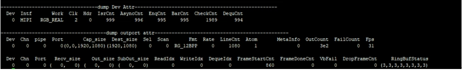
Record the current VIF usage status and device/outport attributes, you can get this information dynamically, which is convenient for debugging and testing.
-
Parameter Description
Parameter Description Dev Attr u32VifDevIdx Dev ID Intf Protocol for entering data Clk Runmode Hdr Hdr type IsrCnt Frame start callback count yncCnt/EnqCnt/ BarCnt/CheckCnt/ DequCnt Callback interface execution times OutPort Attr Chn Channel id Pipe Pipe id Port Port id Cap_size input size Dest_size output size Sel Frame selection Scan Scan mode, progressive or interlaced Fmt Output pixel format Rate Frame rate type LineCnt Frame mode line count Atom The number of buffers held by the bottom layer MetaInfo Frame id Outcount Output frame count Failcount Failed to get outputbuffer count Fps Frame per second Recv_size Vif hardware received size Out_size Write dma size SubOut_size Write sub dma size ReadIdx/WriteIdx/ DequeIdx Read,write,deque 的 index FrameStartCnt Which frame is processed to FrameDoneCnt How many frames are processed VbFail VbFail count DropFrameCnt Drop frame count RingBufStatus Ring buf status
5.2. echo
| Function | Dump frame to the specified path. |
|---|---|
| Command | echo dump [chnid portid /path] > /proc/mi_modules/mi_vif/mi_vif0 |
| Parameter Description | Chnid: channel id Portid: port id Path: dumped path |
| Example | echo dump 0 0 /tmp > /proc/mi_modules/mi_vif/mi_vif0 |
| Function | Set the number of atoms in vif. |
|---|---|
| Command | echo initatom [chnid InitAtom] > /proc/mi_modules/mi_vif/mi_vif0 |
| Parameter Description | Chnid: channel id InitAtom: The maximum number of buffers held by the Driver |
| Example | echo initatom 0 2 > /proc/mi_modules/mi_vif/mi_vif0 |
| Function | Set timer |
|---|---|
| Command | echo usetimer [devid bUseTimer] > /proc/mi_modules/mi_vif/mi_vif0 |
| Parameter Description | devid: device id bUseTimer: Enable timer |
| Example | echo usetimer 0 1 > /proc/mi_modules/mi_vif/mi_vif0 |