SSD_Sensor Porting Guide
1. SENSOR PORTING RELATED HARDWARE INFORMATION
This document describes how to porting SigmaStar sensor driver including basic hardware knowledge, software control sensor API (sensor handle), sensor interface API (Sensor-IF) of SigmaStar and software porting flow. In this document, we take the sensor driver of imx415/imx335/sc2315/sc2335 as examples. You can follow the instructions in this document to complete the sensor porting step by step.
First we introduce the relevant knowledge of hardware and corresponding source code to make it easier to understand for you.
1.1. Sensor power sequence
Check the power-on sequence spec in the sensor datasheet. Please follow below power sequence 1.1V > 1.8V > 2.9V as the imx415 sensor datasheet required.
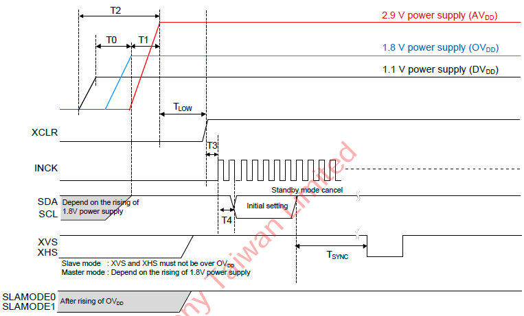
Figure 1: the IMX415 sensor power sequence spec
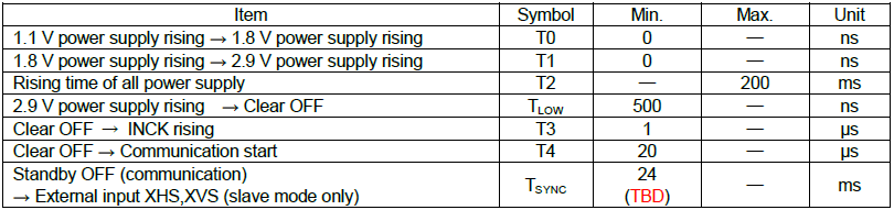
Table 1: the IMX415 sensor power sequence timing table
-
Corresponding source code
You can control sensor power-on and reset pins through “handle->pCus_sensor_poweron” in the sensor driver handle initial function. If you need to modify sensor power sequence timing, please check the characteristics of sensor and hardware design.
static int pCus_poweron(ms_cus_sensor *handle, u32 idx)  {
    ISensorIfAPI *sensor_if = &handle->sensor_if_api;
    //Sensor power on sequence
    sensor_if->PowerOff(idx, handle->pwdn_POLARITY);   // Powerdn Pull Low
    sensor_if->Reset(idx, handle->reset_POLARITY);     // Rst Pull Low
    sensor_if->SetIOPad(idx, handle->sif_bus, handle->interface_attr.attr_mipi.mipi_lane_num);
    sensor_if->SetCSI_Clk(idx, CUS_CSI_CLK_216M);
    sensor_if->SetCSI_Lane(idx, handle->interface_attr.attr_mipi.mipi_lane_num, ENABLE);
    sensor_if->SetCSI_LongPacketType(idx, 0, 0x1C00, 0);
    if (handle->interface_attr.attr_mipi.mipi_hdr_mode == CUS_HDR_MODE_SONY_DOL)
        sensor_if->SetCSI_hdr_mode(idx, handle->interface_attr.attr_mipi.mipi_hdr_mode, 1);

    sensor_if->PowerOff(idx, !handle->pwdn_POLARITY);
    //Sensor board PWDN Enable, 1.8V & 2.9V need 30ms then Pull High
    SENSOR_MSLEEP(31);
    sensor_if->Reset(idx, !handle->reset_POLARITY);
    SENSOR_UDELAY(1);
    sensor_if->MCLK(idx, 1, handle->mclk);
    SENSOR_DMSG("Sensor Power On finished\n");
    return SUCCESS;
}
NOTE: Below is SigmaStar Sensor board schematic of power circuit. 1.1V, 1.8V, 2.9V power will pull high after power-on enable. First 1.1V, then 1.8V and 2.9V, you can use an oscilloscope to measure it on your sensor board.
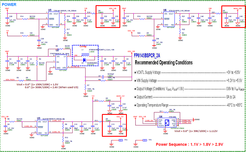
Figure 2: the IMX415 sensor power circuit
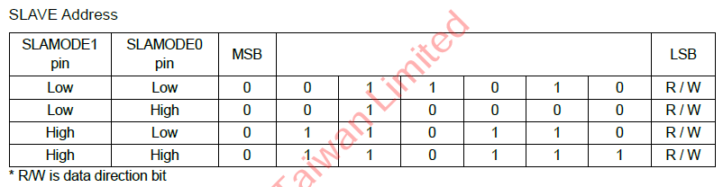
1.2. Sensor IC slave address check
SigmaStar SoC needs to communicate with a sensor through I2C, please check the sensor I2C slave address first.
Table 2: the IMX415 sensor slave id table
NOTE: Check the sensor board schematic of I2C slave mode Option
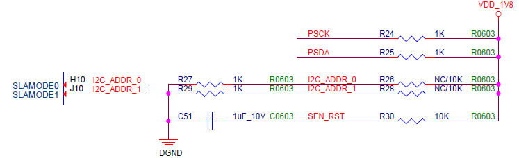
Figure 3: the IMX415 sensor board I2C slave mode
-
Corresponding source code
The sensor driver I2C Setting in Marco define
////////////////////////////////////
// I2C Info                         //
////////////////////////////////////
#define SENSOR_I2C_ADDR     0x34        //I2C slave address
#define SENSOR_I2C_SPEED    300000      //I2C speed, 60000~320000
//#define SENSOR_I2C_CHANNEL   1        //I2C Channel
//#define SENSOR_I2C_PAD_MODE  2        //Pad/Mode Number
#define SENSOR_I2C_LEGACY  I2C_NORMAL_MODE  //usually set CUS_I2C_NORMAL_MODE,  if use old OVT I2C protocol=> set CUS_I2C_LEGACY_MODE
#define SENSOR_I2C_FMT     I2C_FMT_A16D8 //CUS_I2C_FMT_A8D8, CUS_I2C_FMT_A8D16, CUS_I2C_FMT_A16D8, CUS_I2C_FMT_A16D16
NOTE: Sensor-IF of I2C control Interface in handle initial function
handle->i2c_cfg.mode     = SENSOR_I2C_LEGACY;    //(CUS_ISP_I2C_MODE) FALSE;
handle->i2c_cfg.fmt      = SENSOR_I2C_FMT;       //CUS_I2C_FMT_A16D16;
handle->i2c_cfg.address  = SENSOR_I2C_ADDR;      //0x34;
handle->i2c_cfg.speed    = SENSOR_I2C_SPEED;     //300000;
1.3. Sensor MCLK support
Each sensor can support in different MCLK. That the MCLK list table that we can provide is as follows. You can find the MCLK corresponding to the sensor from the initialization settings provided by the sensor vendor. The sensor MCLK Setting in Marco define
-
Corresponding source code
////////////////////////////////////
// MCLK Info                        //
////////////////////////////////////
/*******I5/MACARON Support MCLK List*******
*    CUS_CMU_CLK_27MHZ   / CUS_CMU_CLK_21P6MHZ  / CUS_CMU_CLK_12MHZ,
*    CUS_CMU_CLK_5P4MHZ  / CUS_CMU_CLK_36MHZ    / CUS_CMU_CLK_54MHZ,
*    CUS_CMU_CLK_43P2MHZ / CUS_CMU_CLK_61P7MHZ  / CUS_CMU_CLK_72MHZ,
*    CUS_CMU_CLK_48MHZ    / CUS_CMU_CLK_24MHZ    / CUS_CMU_CLK_37P125MHZ,
******End of Support MCLK List*******/
#define Preview_MCLK_SPEED           CUS_CMU_CLK_27MHZ
#define Preview_MCLK_SPEED_HDR_DOL  CUS_CMU_CLK_37P125MHZ
NOTE: The sensor MCLK control Interface in handle initial function
////////////////////////////////////
//    mclk                        //
////////////////////////////////////
handle->mclk                   = UseParaMclk(SENSOR_DRV_PARAM_MCLK());
2. Sensor porting relevant software control
After introducing the relevant knowledge of hardware and corresponding source code, we will introduce software control API (sensor handle) and sensor interface API (Sensor-IF) of SigmaStar in this part.
2.1. Sensor driver support mode define
Register the sensor support behavior mode. For example, the IMX415 sensor supports linear and HDR mode, you can refer to the IMX415 sensor driver and fill it in define of “SENSOR_DRV_ENTRY_IMPL_END_EX”.
SENSOR_DRV_ENTRY_IMPL_END_EX(  IMX415_HDR,
                            cus_camsensor_init_handle,
                            cus_camsensor_init_handle_hdr_dol_sef,
                            cus_camsensor_init_handle_hdr_dol_lef,
                            imx415_params
                            );
Table 3: the sensor driver “SENSOR_DRV_ENTRY_IMPL_END_EX” define
| Parameter | Describe |
|---|---|
| Name | Sensor Name and support mode |
| LinearEntry | Sensor Linear mode handle initial function |
| HdrSefEntry | Sensor HDR Short Exposure handle initial function |
| HdrLefEntry | Sensor HDR Long Exposure handle initial function |
| PrivateDataType | Sensor Private Data Type |
2.1.1. Introduce “SENSOR_DRV_IMPL_END_EX”
You can check macro define “SENSOR_DRV_ENTRY_IMPL_END_EX” more detail in the path “driver/SensorDriver/drv/inc/drv_sensor_common.h”. LinearEntry has a group of private data set, HdrSefEntry and HdrLefEntry have another a group of private data set.
#define SENSOR_DRV_ENTRY_IMPL_END_EX (Name,LinearEntry,HdrSefEntry,HdrLefEntry,PrivateDataType)\
static PrivateDataType* g_pData[2][MAX_CAMID_LEN] = { {0,0,0,0}, {0,0,0,0} };\
int Name##_init_driver(unsigned char chmap)\
{\
    int nCamID=0;\
    /*To avoid compile warning*/\
    void* p0 = LinearEntry;\
    void* p1 = HdrSefEntry;\
    void* p2 = HdrLefEntry;\
    if(DrvSensorHandleVer(CUS_CAMSENSOR_HANDLE_MAJ_VER, CUS_CAMSENSOR_HANDLE_MIN_VER)==FAIL)\
    return FAIL;\
    if(DrvSensorIFVer(CUS_CAMSENSORIF_MAJ_VER, CUS_CAMSENSORIF_MIN_VER)==FAIL)\
    return FAIL;\
    if(DrvSensorI2CVer(CUS_CAMSENSOR_I2C_MAJ_VER, CUS_CAMSENSOR_I2C_MIN_VER)==FAIL)\
    return FAIL;\
    for(nCamID=0;nCamID<MAX_CAMID_LEN;++nCamID)\
    {\
        if((chmap>>nCamID)&0x1)\
        {\
            if(p0){\
                void* pData = CamOsMemAlloc(sizeof(PrivateDataType));\
                memset(pData,0,sizeof(PrivateDataType));\
                DrvRegisterSensorDriverEx(nCamID, LinearEntry,pData);\
                DrvRegisterSensorI2CSlaveID(nCamID, (i2c_slave_id>>(nCamID*8))&0xFF);\
                SENSOR_DMSG("Connect %s linear to sensor pad %d\n",__FUNCTION__, nCamID);\
                g_pData[0][nCamID] = pData;\
            }\
            if(p1||p2){\
                void* pData = CamOsMemAlloc(sizeof(PrivateDataType));\
                memset(pData,0,sizeof(PrivateDataType));\
                if(p1){\
                    DrvRegisterPlaneDriverEx(nCamID, 1, HdrSefEntry,pData);\
                    DrvRegisterPlaneI2CSlaveID(nCamID, 1, (i2c_slave_id>>(nCamID*8))&0xFF);\
                    SENSOR_DMSG("Connect %s SEF to vif sensor pad %d\n",__FUNCTION__, nCamID);\
                }\
                if(p2){\
                    DrvRegisterPlaneDriverEx(nCamID, 0, HdrLefEntry,pData);\
                    DrvRegisterPlaneI2CSlaveID(nCamID, 1, (i2c_slave_id>>(nCamID*8))&0xFF);\
                    SENSOR_DMSG("Connect %s LEF to sensor pad %d\n",__FUNCTION__, nCamID);\
                }\
                g_pData[1][nCamID] = pData;\
            }\
        }\
    }\
    return 0;\
}\
2.2. Sensor driver handle function
Next we will introduce and explain handle API in the linear and HDR handle initial functions. We can control, set or read any state of the sensor through the handle API. Here we take the sensor driver of imx415 as an example. You can step through the sensor porting of linear and HDR mode according to the instructions in this document.
2.2.1. Handle of IC API
Set I2C hardware information
Table 4: handle of I2C API define
| Parameter | Describe | NOTE |
|---|---|---|
| handle->i2c_cfg.mode | Register I2C Mode | I2C_NORMAL_MODE /**\< Sensor driver can only use I2C_NORMAL_MODE */ I2C_LEGACY_MODE, /**\< Do not use */ |
| handle->i2c_cfg.fmt | Register set I2C format for bit of address & data length. | /**\< I2C_FMT_A16D8 means 16 bits Address, 8 bits Data */ I2C_FMT_A8D8, I2C_FMT_A16D8, I2C_FMT_A8D16, I2C_FMT_A16D16, I2C_FMT_END /**\< Reserved */ |
| handle->i2c_cfg.address | Register set sensor I2C slave address, SigmaStar SoC supports 8bits slave address | Check From Sensor Datasheet |
| handle->i2c_cfg.speed | Register set sensor max I2C speed (MACARON fixed at 300 KHz) | I2C speed, 60000~320000 |
2.2.2. Handle of MCLK API
Set the sensor MCLK information
Table 5: handle of MCLK API define
| handle->mclk | Register set VIF module output MCLK to sensor For MI Query!! | Main Chip Support MCLK List as : CUS_CMU_CLK_27MHZ, CUS_CMU_CLK_21P6MHZ, CUS_CMU_CLK_12MHZ, CUS_CMU_CLK_5P4MHZ, CUS_CMU_CLK_36MHZ, CUS_CMU_CLK_54MHZ, CUS_CMU_CLK_43P2MHZ, CUS_CMU_CLK_61P7MHZ, CUS_CMU_CLK_72MHZ, CUS_CMU_CLK_48MHZ, CUS_CMU_CLK_24MHZ, CUS_CMU_CLK_37P125MHZ, CUS_CMU_CLK_LPLL_DIV1, CUS_CMU_CLK_LPLL_DIV2, CUS_CMU_CLK_LPLL_DIV4, CUS_CMU_CLK_LPLL_DIV8, |
|---|---|---|
2.2.3. Handle of Sensor model id API
Set sensor name and mode information
Table 6: handle of model id API define
| Parameter | Describe | NOTE |
|---|---|---|
| handle->model_id | Register set sensor model for libcamera user by using | MIPI IMX415_MIPI |
| PARALLEL IMX323_PARL | ||
| HDR IMX415_MIPI_HDR_SEF IMX415_MIPI_HDR_LEF |
2.2.4. Handle of sensor interface and output hardware information
Table 7: handle of Sensor interface and output hardware information API define
| Parameter | Describe | NOTE |
|---|---|---|
| handle->pCus_sensor_poweron | Fill Up Sensor IF Info!!! Register set sensor power-on sequence function. | Function ref : pCus_poweron |
| handle->pCus_sensor_init | Register load sensor initial setting function. | |
| handle->pCus_sensor_post_init | Set and enable SoC mipi csi status. | Special case is like SmartSens product SC4236/SC2315 |
| handle->isp_type | Register ISP type (not used in MACARON) | SENSOR_ISP_TYPE ISP_SOC, /**\< Not support */ ISP_EXT, /**\< sensor without built-in ISP */ |
| handle->sif_bus | Register set sensor interface bus type | SENSOR_IFBUS_TYPE CUS_SENIF_BUS_PARL = 0, /**\< sensor data bus is parallel */ CUS_SENIF_BUS_MIPI = 1, /**\< sensor data bus is mipi */ CUS_SENIF_BUS_BT601 = 2, CUS_SENIF_BUS_BT656 = 3, CUS_SENIF_BUS_BT1120 = 4, |
| handle->data_prec | Register set sensor output raw data precision | SENSOR_DATAPREC CUS_DATAPRECISION_8 = 0, /**\< raw data precision 8bits */ CUS_DATAPRECISION_10 = 1, /**\< raw data precision 10bits */ CUS_DATAPRECISION_16 = 2, /**\< raw data precision 16bits */ CUS_DATAPRECISION_12 = 3, /**\< raw data precision 12bits */ CUS_DATAPRECISION_14 = 4, /**\< raw data precision 14bits */ |
| handle->data_mode | Register set sensor bayer raw (8/10-bits) to 12-bits mode (Not used in MACARON) | SENSOR_DATAMODE CUS_SEN_8TO12_7074, CUS_SEN_8TO12_7000, CUS_SEN_8TO12_114118, CUS_SEN_8TO12_11400, CUS_SEN_10TO12_9098, CUS_SEN_10TO12_9000, CUS_SEN_10TO12_1121110, CUS_SEN_10TO12_11200 |
| handle->bayer_id | Register set sensor bayer raw start id | SENSOR_BAYERID CUS_BAYER_RG = 0, CUS_BAYER_GR, CUS_BAYER_BG, CUS_BAYER_GB, |
| handle->RGBIR_id | Register set sensor RGB-IR start id  #If NOT RGB-IR sensor, please set CUS_RGBIR_NONE |
SENSOR_RGBIRID CUS_RGBIR_NONE = 0, CUS_RGBIR_R0 = 1, CUS_RGBIR_G0 = 2, CUS_RGBIR_B0 = 3, CUS_RGBIR_G1 = 4, CUS_RGBIR_G2 = 5, CUS_RGBIR_I0 = 6, CUS_RGBIR_G3 = 7, CUS_RGBIR_I1 = 8 |
| handle->orient | Register get sensor image mirror-flip default status | SENSOR_ORIT CUS_ORIT_M0F0, /**\< mirror, flip unchanged */ CUS_ORIT_M1F0, /**\< mirror changed */ CUS_ORIT_M0F1, /**\< flip changed */ CUS_ORIT_M1F1, /**\< mirror and flip changed */ |
| handle->snr_pad_group | Register sensor pad group | CUS_SENSOR_PAD_GROUP_A = 0, CUS_SENSOR_PAD_GROUP_B = 1, CUS_SENSOR_PAD_GROUP_A = 0, CUS_SENSOR_PAD_GROUP_B = 1, |
| handle->snr_pad_mode | Register sensor master and slave mode | CUS_SENSOR_MASTER_MODE = 0, CUS_SENSOR_SLAVE_MODE = 1, |
| handle->ir_only_fmt | Register sensor ir format status | |
| For HDR (MIPI) Interface | ||
| handle->interface_attr.attr_mipi.mipi_lane_num | Register set MIPI lane number | Default : 4 |
| handle->interface_attr.attr_mipi.mipi_data_format | Register set MIPI data format | CUS_SEN_INPUT_FORMAT_YUV422, CUS_SEN_INPUT_FORMAT_RGB, |
| handle->interface_attr.attr_mipi.mipi_yuv_order | Register set MIPI yuv order | For yuv sensor only |
| handle->interface_attr.attr_mipi.mipi_hsync_mode | Register set HDR virtual channel0 hsync mode | SENSOR_MIPI_HSYNC_MODE PACKET_HEADER_EDGE1 = 0, /**\< packet header edge */ PACKET_HEADER_EDGE2 = 1, /**\< line end edge */ PACKET_HEADER_EDGE3 = 2, /**\< line start edge */ PACKET_FOOTER_EDGE = 3, /**\< packet footer edge */ |
| handle->interface_attr.attr_mipi.mipi_hdr_mode | Register set MIPI HDR mode | CUS_HDR_MODE_NONE = 0, CUS_HDR_MODE_SONY_DOL = 1, CUS_HDR_MODE_DCG = 2, CUS_HDR_MODE_EMBEDDED_RAW8 = 3, CUS_HDR_MODE_EMBEDDED_RAW10 = 4, CUS_HDR_MODE_EMBEDDED_RAW12 = 5, CUS_HDR_MODE_EMBEDDED_RAW16 = 6, //Only for OV2718? CUS_HDR_MODE_LI = 7, |
| handle->interface_attr.attr_mipi. mipi_sampling_delay | MIPI CLK skip time (ns) (Not used in MACARON) | |
| handle->interface_attr.attr_mipi.mipi_hdr_virtual_channel_num | Register set HDR virtual channel number #Based on each sensor VC mode header define | For example imx415: Long Exposure Frame : 0 Short Exposure Frame : 1 |
2.2.5. Handle of signal polarity API
Set SoC hardware signal polarity
Table 8: handle of signal polarity API define
| Parameter | Describe | NOTE |
|---|---|---|
| handle->pwdn_POLARITY | Register set output sensor power-down pin (GPIO) polarity | SENSOR_PWDN_POL CUS_CLK_POL_POS = 0, /**\< High active */ CUS_CLK_POL_NEG /**\< Low active */ |
| handle->reset_POLARITY | Register set output sensor reset pin (GPIO) polarity | SENSOR_RST_POL CUS_CLK_POL_POS = 0, /**\< High active */ CUS_CLK_POL_NEG /**\< Low active */ |
| For Parallel Interface | ||
| handle->VSYNC_POLARITY | Register set receive sensor Vsync pin signal polarity | SENSOR_VSYNC_POL CUS_CLK_POL_POS = 0, /**\< High active */ CUS_CLK_POL_NEG /**\< Low active */ |
| handle->HSYNC_POLARITY | Register set receive sensor Hsync pin signal polarity | SENSOR_HSYNC_POL CUS_CLK_POL_POS = 0, /**\< High active */ CUS_CLK_POL_NEG /**\< Low active */ |
| handle->PCLK_POLARITY | Register set receive sensor pixel clk pin signal polarity | SENSOR_PCLK_POL CUS_CLK_POL_POS = 0, /**\< High active */ CUS_CLK_POL_NEG /**\< Low active */ |
2.2.6. Handle of sensor resolution capability API
Set sensor support and implement output image information.
Table 9: handle of sensor resolution capability API define
| Parameter | Describe | NOTE |
|---|---|---|
| handle->video_res_supported.num_res | Register set sensor support resolution number | |
| handle->video_res_supported.ulcur_res | Register set sensor current resolution | Default : 0 |
| handle->video_res_supported.res[n].width | Register set sensor support width | |
| handle->video_res_supported.res[n].height | Register set sensor support height | |
| handle->video_res_supported.res[n].max_fps | Register set sensor support preview maximum fps | |
| handle->video_res_supported.res[n].min_fps | Register set sensor support preview minimum fps | |
| handle->video_res_supported.res[n].crop_start_x | Register set VIF crop sensor output image start of X | |
| handle->video_res_supported.res[n].crop_start_y | Register set VIF crop sensor output image start of Y | |
| handle->video_res_supported.res[n].nOutputWidth | Register set VIF output active pixel | |
| handle->video_res_supported.res[n].nOutputHeight | Register set VIF output active line | |
| handle->video_res_supported.res[n].strResDesc | Register set sensor resolution & fps string | EX: 1920x1080\@30fps |
2.2.7. Handle of set/get sensor control API
We can load sensor initial setting, switch sensor output resolution, sensor mirror or flip and fps set or get through these functions.
Table 10: handle of set/get sensor control API define
| Parameter | Describe | NOTE |
|---|---|---|
| handle->pCus_sensor_release | Register sensor release function. | Function ref : cus_camsensor_release_handle |
| handle->pCus_sensor_init | Register load sensor initial setting function. | Function ref : pCus_init_mipi4lane_linear |
| handle->pCus_sensor_poweron | Register set sensor power-on sequence function. | Function ref : pCus_poweron |
| handle->pCus_sensor_poweroff | Register set sensor power-off sequence function. | Function ref : pCus_poweroff |
| handle->pCus_sensor_GetSensorID | Register get and check sensor ID | Function ref : pCus_GetSensorID |
| handle->pCus_sensor_GetVideoResNum | Register get sensor support resolution number function, that’s video output index. | Function ref : pCus_GetVideoResNum |
| handle->pCus_sensor_GetVideoRes | Register get sensor support preview info function (width, height, and frame rate). | Function ref : pCus_GetVideoRes |
| handle->pCus_sensor_GetCurVideoRes | Register get sensor current preview info function (width, height, and frame rate). | Function ref : pCus_GetCurVideoRes |
| handle->pCus_sensor_SetVideoRes | Register switch sensor and load initial setting function. | Function ref : pCus_SetVideoRes |
| handle->pCus_sensor_GetOrien | Register get sensor mirror-flip status function. | Function ref : pCus_GetOrien |
| handle->pCus_sensor_SetOrien | Register set Sensor mirror-flip status function. | Function ref : pCus_SetOrien |
| handle->pCus_sensor_GetFPS | Register get sensor FPS status function. | Function ref : pCus_GetFPS |
| handle->pCus_sensor_SetFPS | Register set sensor FPS status function. | Function ref : pCus_SetFPS |
| handle->pCus_sensor_SetPatternMode | Set sensor test pattern (Color Bar Pattern). |
2.2.8. Handle of set/get sensor AE control API
First we will introduce the sensor driver private data in this part, this purpose is to record the parameters of the sensor without any modification. Here is imx415 as a reference example. The naming can be customized according to each sensor or developer, and there is no mandatory requirement.
Table 11: example for imx415 private data
| Parameter | Describe | NOTE |
|---|---|---|
| params->tGain_reg | Register set each frame sensor AE gain parameter. | For imx415 Linear |
| params->tExpo_reg | Register set each frame sensor exposure line parameter. | For imx415 Linear |
| params->tVts_reg | Register set each frame sensor total line parameter. | For imx415 Linear, LEF |
| params->tSHR0_reg | Register set each frame long exposure frame shutter time. | For imx415 LEF |
| params->tRHS1_reg | Register set each frame readout time of short exposure frame. | For imx415 SEF |
| params->tSHR1_reg | Register set each frame short exposure frame shutter time. | For imx415 SEF |
| params->tGain_hdr_dol_lef_reg | Register set each frame long exposure frame HDR AE Gain. | For imx415 LEF |
| params->tGain_hdr_dol_sef_reg | Register set each frame short exposure frame HDR AE Gain. | For imx415 SEF |
| params->expo.vts | Register set each frame total line. | For imx415 Linear, LEF |
| params->expo.expo_lines | Register set each frame exposure line. | For imx415 Linear, LEF |
| params->expo.fps | Register set sensor fps. | For imx415 Linear, LEF |
| OTHERS |
We can set or get sensor AE function status through this API, including AE shutter time, gain, limit AE setting value and AE update timing, etc.
Table 12: handle of set/get sensor AE control API define
| Parameter | Describe | NOTE |
|---|---|---|
| handle->ae_gain_delay | Register set sensor AE Gain effective frame after setting frame. | Based On Sensor Characteristic Please check *SUPPLYMENT4.2 |
| handle->ae_shutter_delay | Register set sensor AE Shutter effective frame after setting frame. | Based On Sensor Characteristic Please check *SUPPLYMENT4.2 |
| handle->ae_gain_ctrl_num | Register set sensor AE Gain table number. | Linear mode set to 1 HDR mode set to 2 |
| handle->ae_shutter_ctrl_num | Register set sensor AE Shutter table number. | Linear mode set to 1 HDR mode set to 2 |
| handle->sat_mingain | Register get sensor Initial minimum Gain. | Minimum Gain != 1 |
| handle->pCus_sensor_AEStatusNotify | Register update AE Gain, Shutter and fps status at frame start or frame end. | Function Ref : pCus_AEStatusNotify Status 0 is frame end update Status 1 is frame start update |
| handle->pCus_sensor_GetAEUSecs | Register get sensor output image exposure time. | Function Ref : pCus_GetAEUSecs |
| handle->pCus_sensor_SetAEUSecs | Register set sensor output image exposure time. | Function Ref : pCus_SetAEUSecs |
| handle->pCus_sensor_GetAEGain | Register get sensor AE Gain. | Function Ref : pCus_GetAEGain |
| handle->pCus_sensor_SetAEGain | Register set sensor AE Gain. | Function Ref : pCus_SetAEGain |
| handle->pCus_sensor_GetAEMinMaxGain | Register get sensor minimum & maximum Gain information | Function Ref : pCus_GetAEMinMaxGain |
| handle->pCus_sensor_GetAEMinMaxUSecs | Register get sensor minimum & maximum exposure time | Function Ref : pCus_GetAEMinMaxUSecs |
| handle->pCus_sensor_GetShutterInfo | Register get sensor minimum & maximum exposure in line, and shutter step | Function: |
2.2.9. Sensor-IF API
SENSOR_IF API for Connect with the sensor driver and the VIF driver, this callback control in below handle control function.
We will introduce and describe this API, more detail you can reference the sensor driver of IMX415.
| Parameter | Describe | NOTE |
|---|---|---|
| sensor_if->PowerOff | Set Sensor-IF PowerDown pull high or not. | Callback to VIF driver |
| sensor_if->Reset | Set Sensor-IF SW RESET pull high or not. | Callback to VIF driver |
| sensor_if->MCLK | Set VIF Output MCLK | Callback to VIF driver |
| sensor_if->SetIOPad | For SENSOR-IF I/O Bus Mode | Callback to VIF driver |
| sensor_if->QueryMCLK | For query sensor master clock | Callback to VIF driver |
| sensor_if->QueryLaneNum | For query sensor MIPI lane number | Callback to VIF driver |
| sensor_if->SetSkipFrame | Skip vif output frame | Callback to VIF driver |
| For MIPI Interface | ||
| sensor_if->SetCSI_Clk | Set MIPI Interface MAC CLK | Callback to VIF driver |
| sensor_if->SetCSI_Lane | Set MIPI Interface Data Lane | Callback to VIF driver |
| sensor_if->SetCSI_hdr_mod | Set HDR Data Format | Callback to VIF driver |
| sensor_if->SetCSI_LongPacketType | Set MIPI Long Packet Type | Callback to VIF driver |
| sensor_if->SetCSI_clk_data_skip | Skip hs clock when into HSRX mode | Callback to VIF driver |
| sensor_if->VCOHsmode | Callback to VIF driver |
3. Software porting flow
This chapter introduces the process of software porting sensor driver. First, it will explain how to initialize the sensor. Then describe the information required by the sensor driver 3A and control the functions that 3A will call.
3.1. The sensor driver initial flow introduction
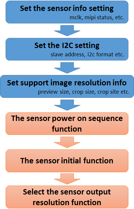
Figure 4: porting the sensor driver flow
This document introduces the initial process of transplanting the sensor according to the process in the figure above.
3.1.1. Set the sensor information setting
These settings are the hardware information of the sensor, we have listed the necessary hardware information, you can refer to the IMX415 / IMX335 sensor driver,
////////////////////////////////////
// Sensor-If Info                 //
////////////////////////////////////
//MIPI config begin.
#define SENSOR_MIPI_LANE_NUM        (lane_num)          //IMX335 Linear mode supports MIPI 2/4 Lane
#define SENSOR_MIPI_LANE_NUM_DOL    (4) //(hdr_lane_num)//IMX335 DOL mode supports MIPI 4 Lane
//#define SENSOR_MIPI_HDR_MODE        (0) //0: Non-HDR mode. 1:Sony DOL mode

#define SENSOR_ISP_TYPE             ISP_EXT             //ISP_EXT, ISP_SOC (Non-used)
//#define SENSOR_DATAFMT             CUS_DATAFMT_BAYER    //CUS_DATAFMT_YUV, CUS_DATAFMT_BAYER
#define SENSOR_IFBUS_TYPE           CUS_SENIF_BUS_MIPI  //CFG //CUS_SENIF_BUS_PARL, CUS_SENIF_BUS_MIPI
#define SENSOR_MIPI_HSYNC_MODE      PACKET_HEADER_EDGE1
#define SENSOR_MIPI_HSYNC_MODE_HDR_DOL PACKET_FOOTER_EDGE
#define SENSOR_DATAPREC             CUS_DATAPRECISION_10
#define SENSOR_DATAPREC_DOL         CUS_DATAPRECISION_10
#define SENSOR_DATAMODE             CUS_SEN_10TO12_9098  //CFG
#define SENSOR_BAYERID              CUS_BAYER_RG         //0h: CUS_BAYER_RG, 1h: CUS_BAYER_GR, 2h: CUS_BAYER_BG, 3h: CUS_BAYER_GB
#define SENSOR_BAYERID_HDR_DOL     CUS_BAYER_RG
#define SENSOR_RGBIRID              CUS_RGBIR_NONE
#define SENSOR_ORIT                 CUS_ORIT_M0F0        //CUS_ORIT_M0F0, CUS_ORIT_M1F0, CUS_ORIT_M0F1, CUS_ORIT_M1F1,
//#define SENSOR_YCORDER              CUS_SEN_YCODR_YC     //CUS_SEN_YCODR_YC, CUS_SEN_YCODR_CY
//#define long_packet_type_enable     0x00 //UD1~UD8 (user define)

////////////////////////////////////
// MCLK Info                        //
////////////////////////////////////
#define Preview_MCLK_SPEED          CUS_CMU_CLK_27MHZ//CUS_CMU_CLK_37P125MHZ//CUS_CMU_CLK_27MHZ
#define Preview_MCLK_SPEED_HDR_DOL  CUS_CMU_CLK_27MHZ
3.1.2. Set the sensor IC setting
SoC communicates with sensors mainly through I2C. Therefore, you need to set I2C before sending sensor setting value to the sensor.
Please refer to this document chapter 1.2.
3.2. Set support image resolution information
You need to fill in the sensor image information provided by the sensor provider FAE. This information includes preview size, image crop size and site etc. We define this information as a global variable.
////////////////////////////////////
// Image Info                     //
////////////////////////////////////
static struct {     // LINEAR
    // Modify it based on number of support resolution
    enum {LINEAR_RES_1 = 0, LINEAR_RES_2, LINEAR_RES_3, LINEAR_RES_4, LINEAR_RES_5, LINEAR_RES_6, LINEAR_RES_7, LINEAR_RES_8, LINEAR_RES_END}mode;
    // Sensor Output Image info
    struct _senout{
        s32 width, height, min_fps, max_fps;
    }senout;
    // VIF Get Image Info
    struct _sensif{
        s32 crop_start_X, crop_start_y, preview_w, preview_h;
    }senif;
    // Show resolution string
    struct _senstr{
        const char* strResDesc;
    }senstr;
}imx415_mipi_linear[] = {
    {LINEAR_RES_1, {3860, 2250, 3, 20}, {0, 0, 3840, 2160}, {"3840x2160@20fps"} },
    {LINEAR_RES_2, {3096, 2190, 3, 30}, {0, 0, 3072, 2048}, {"3072x2048@30fps"} }, // Modify it
    {LINEAR_RES_3, {3096, 1758, 3, 30}, {0, 0, 3072, 1728}, {"3072x1728@30fps"} }, // Modify it
    {LINEAR_RES_4, {2616, 1974, 3, 30}, {0, 0, 2592, 1944}, {"2592x1944@30fps"} }, // Modify it
    {LINEAR_RES_5, {2976, 1686, 3, 30}, {0, 0, 2944, 1656}, {"2944x1656@30fps"} }, // Modify it
    {LINEAR_RES_6, {2592, 1470, 3, 30}, {0, 0, 2560, 1440}, {"2560x1440@30fps"} }, // Modify it
    {LINEAR_RES_7, {1920, 1080, 3, 60}, {0, 0, 1920, 1080}, {"1920x1080@60fps"} }, // Modify it
    {LINEAR_RES_8, {3864, 2192, 3, 30}, {0, 0, 3840, 2160}, {"3840x2160@30fps"} }, // Modify it
    //{LINEAR_RES_9, {2616, 1974, 3, 25}, {0, 0, 2592, 1944}, {"2592x1944@25fps"} }, // Modify it
};
3.2.1. The sensor power on sequence function
Please refer to this document chapter 1.1.
3.2.2. The sensor initial function
Here is the initial setting of the sensor through the i2c device, first read the product ID or sensor ID of the sensor device to ensure that the correct sensor is used. Please refer to the function registered by “handle->pCus_sensor_init”.
3.2.3. Select the sensor output resolution function
MI will get the image resolution information supported by the sensor driver and select one of the sensor's initial settings.
Please refer to the function registered by “handle->pCus_sensor_SetVideoRes”.
3.3. Implement the sensor control function
The functions that the sensor driver needs to support include fps adjustment, AE shutter adjustment, AE gain adjustment, and mirror flip function settings, which we will not describe more detail, because this needs to be implemented according to the characteristics of each sensor.
The following is our control the sensor implement function flow. Relatively, we also need to get the sensor information, please refer to the figure below:
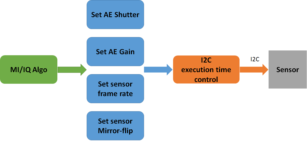
Figure 5: control the sensor implement function flow
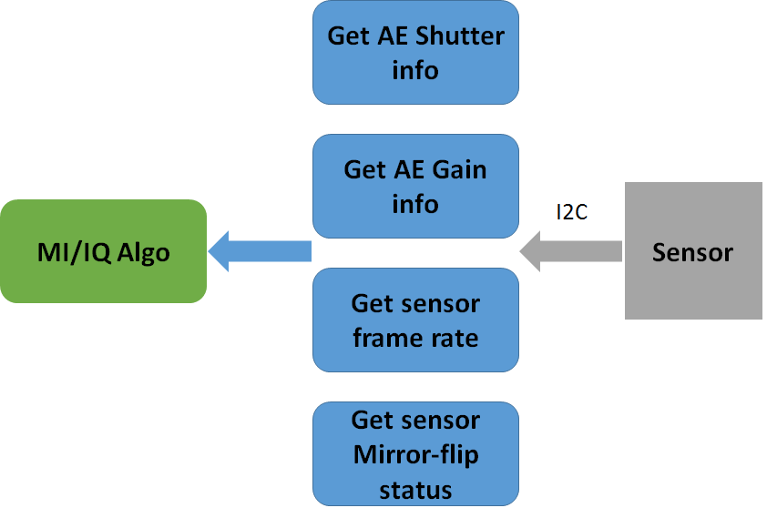
Figure 6: get the sensor implement function information or status
3.3.1. AE shutter control and get AE shutter information
How to control AE shutter, please refer to the function registered by “handle->pCus_sensor_SetAEUSecs”.
Also, ISP algo or MI need to get AE shutter information, please refer to the function registered by “handle->pCus_sensor_GetAEUSecs” and “handle->pCus_sensor_GetShutterInfo”.
3.3.2. AE gain control and get AE gain information
How to control AE gain, please refer to the function registered by “handle->pCus_sensor_SetAEGain”.
Also, ISP algo or MI need to get AE gain information, please refer to the function registered by “handle->pCus_sensor_GetAEGain” and “handle->pCus_sensor_GetAEMinMaxGain”.
3.3.3. Sensor frame rate control and get sensor frame rate information
How to control the sensor output frame rate, please refer to the function registered by “handle->pCus_sensor_SetFPS”.
Also, MI needs to get the sensor output frame rate information, please refer to the function registered by “handle->pCus_sensor_GetFPS”.
3.3.4. Sensor mirror-flip control and get sensor mirror-flip information
How to control the sensor image mirror-flip, please refer to the function registered by “handle->pCus_sensor_SetOrien”.
Also, MI needs to get the sensor image mirror-flip information, please refer to the function registered by “handle->pCus_sensor_GetOrien”.
3.4. IC execution time control
The above AE shutter, AE gain, sensor frame rate and mirror control, we hope everyone can send commands to the sensor through I2C at the same time
So we will implement this using the function "handle->pCus_sensor_AEStatusNotify"
Therefore, we can control the time of I2C send commands to the sensor through two parameters "CUS_FRAME_ACTIVE" and "CUS_FRAME_INACTIVE". Most sensors can be set at the frame start, so the parameter "CUS_FRAME_ACTIVE" can be selected.
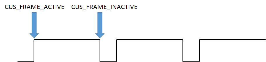
Figure 7: I2C execution time
NOTE:
If the porting sensor cannot find out what caused the image abnormality, you can call “return success” directly in the function.
3.4.1. Sensor AE shutter/gain delay count
How to set “handle->ae_shutter_delay” and “handle->ae_gain_delay”, please refer to this document chapter 4.2.
3.5. Sensor AE shutter/gain delay count
How to set “handle->ae_gain_ctrl_num” and “handle->ae_shutter_ctrl_num”, please refer to this document chapter 2.2.8.
4. Supplyment
4.1. Install the Sensor Driver and parameter introduce
SigmaStar sensor driver provides several installation parameters that can be used when installing the sensor driver. Here are the parameters and instructions as below:
Table 13: sensor driver install parameter
| Parameter | Describe |
|---|---|
| chmap | Specify SoC Channel pad for sensor |
| lane_num | Specify Sensor linear mode MIPI lane number |
| hdr_lane_num | Specify Sensor hdr mode MIPI lane number |
| i2c_slave_id | Specify Sensor i2c slave id |
For example:
| insmod imx335_MIPI.ko chmap=1 lane_num=4 hdr_lane_num=4 i2c_slave_id=0x20 |
|---|
If the above parameters are not used when installing the sensor driver, the default values in the sensor driver are used.
4.2. Verify and debug video stream
The next step is to verify that the sensor driver can be used normally, so, you need to copy app from “/sdk/verify/mi_demo/out/demo/app” to EVB, I take “prog_cus3a” as an example:
/customer # ./prog_cus3a
use default sensor pad 0, vif dev 0
Use HDR ?
0 not use, 1 use DOL
0
You select not use HDR client [548] connected, module:sensor
index 0, Crop(0,0,3840,2160), outputsize(3860,2250), maxfps 20, minfps 3, ResDesc 3840x2160@20fps
index 1, Crop(0,0,3072,2048), outputsize(3096,2190), maxfps 30, minfps 3, ResDesc 3072x2048@30fps
index 2, Crop(0,0,3072,1728), outputsize(3096,1758), maxfps 30, minfps 3, ResDesc 3072x1728@30fps
index 3, Crop(0,0,2592,1944), outputsize(2616,1974), maxfps 30, minfps 3, ResDesc 2592x1944@30fps
index 4, Crop(0,0,2944,1656), outputsize(2976,1686), maxfps 30, minfps 3, ResDesc 2944x1656@30fps
index 5, Crop(0,0,2560,1440), outputsize(2592,1470), maxfps 30, minfps 3, ResDesc 2560x1440@30fps
index 6, Crop(0,0,1920,1080), outputsize(1920,1080), maxfps 60, minfps 3, ResDesc 1920x1080@60fps
index 7, Crop(0,0,3840,2160), outputsize(3864,2192), maxfps 30, minfps 3, ResDesc 3840x2160@30fps
choice which resolution use, cnt 8
4.2.1. Check frame interval
At the same time you can open telnet and enter the following cmd to confirm the VIF and ISP status.
Usually 30fps means that a frame period is 33.3ms.
/ # cat /sys/class/mstar/vif0/vif_ints
== VIF CH-0 ==
Interval(ns)                    : 33309000
VREF_RISING                   : 6147
VREF_FALLING                  : 6149
LINE_CNT_0                    : 2
LINE_CNT_1                    : 2
4.2.2. Check the sensor output stream status
Confirm the information of the sensor signal received by VIF device
/ # cat /sys/class/mstar/vif0/vif_info
== VIF CH-0 ==
INTF_MODE = 4
CH_EN: 1
SRC: MIPI0
INPUT_FMT: RGB
PIX_FMT: 12 bits
HDR_EN: 0
HDR_CH: VC0
CROP_EN: 1
CROP_START_X: 0 - 1919
CROP_START_Y: 0 - 1079
PIXEL_CNT: 1920
LINE_CNT: 1080
4.2.3. Check the ISP status
If the transmission speed of one line or pixel per frame is too fast, even if the VIF can receive the image data normally, there is no guarantee that the ISP can process it immediately, it causes isp fifo full.
/ # cat /sys/class/mstar/isp0/isp_ints
frame_count                     : 1089
u32FrameIntervalNanoSec         : 33332 us
ISP_FIFO_FULL                   : 0
INT_PIPE1_FIFO_FULL             : 0
ISP_BUSY                        : 1089, 06.952374
ISP_IDLE                         : 1090, 06.950575
RDMA0_DONE                     : 0
RDMA1_DONE                     : 0
WDMA0_DONE                    : 0
WDMA1_DONE                    : 0
WDMA6_LINE_HIT                  : 0
WDMA6_DONE                     : 0
ISPIF_VSYNC                       : 1089, 06.952046, 0
AE_DONE                         : 1088, 06.950279, 1934
AE_DONE period                  : 31565 us
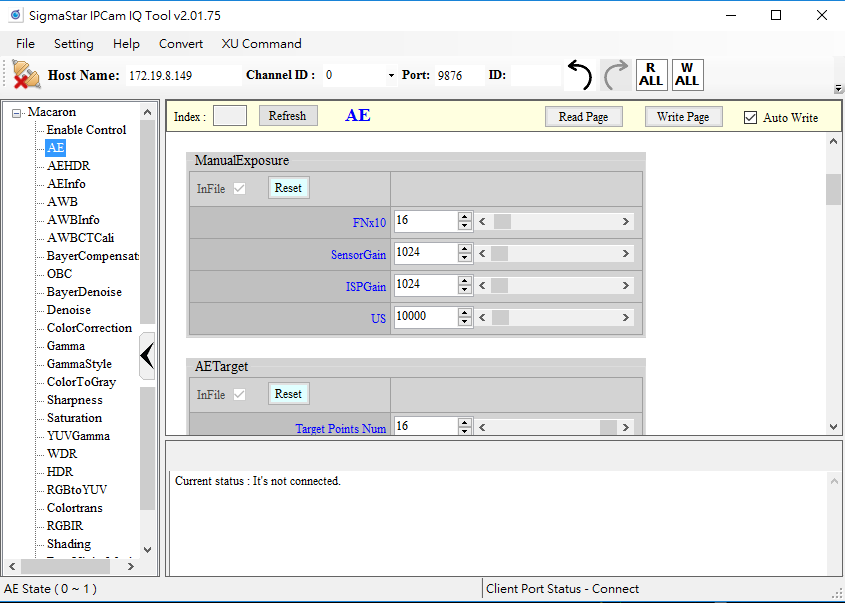
4.3. Verify shutter and gain delay
If you want to verify that the sensor AE gain/shutter delay, you can use apitool, also follow the steps below to control the sensor AE gain/shutter function step by step.
STEP 1. You need to execute process of mixer first
/customer # ./mixer -q -n 1          (linear mode)
/customer # ./mixer -q -n 1 -N 3_2    (hdr mode)
STEP 2. Open IQ tool in sdk path “project/tools/apitool”
STEP 3. Host Name is EVB’s IP address, check it then connect to EVB

STEP 4. Select Macaron AE option, and select “ExposureMode” menu table to M_Mode
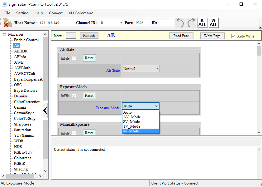
Step 5. Adjust “DebugLev” menu and set AE Debug Level from 0 to 64, then you can check you console log

Check the AE message shown on the console
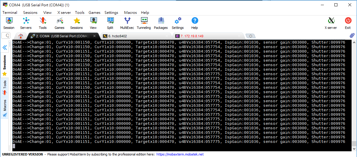
Step 6. Adjust AE sensor gain or shutter manually. At the same time, you can observe the AE message shown on the console.
Observer the value of “CurYx10” change from 308 to 1436

After we set the gain of AE through ISP tool, it will take effect in the next frame. The CurYx10 represents the brightness information of a previous frame. The following figure is an example. The AE gain delay needs to set 2.
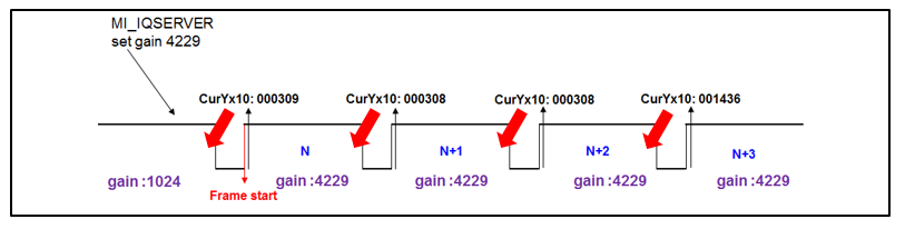
Figure 8: AE Y value response time
4.4. Verify shutter and gain linearity
If you want to verify that the sensor AE gain/shutter function is normal after porting the sensor AE gain/shutter function finish, you can use apitool. You can follow the steps below to control the sensor AE gain/shutter function step by step.
STEP 1. You need to execute process of mixer
/customer # ./mixer -q -n 1        (linear mode)
/customer # ./mixer -q -n 1 -N 3_2    (hdr mode)
STEP 2. Open IQ tool in sdk path “project/tools/apitool”
STEP 3. Host Name is EVB’s IP address, check it then connect to EVB
STEP 4. Select Macaron AE option, and select “ExposureMode” menu table to M_Mode

Step 5. Adjust AE sensor gain and shutter manually. At the same time, you can observe image changes through VLC or your debug message.

The IQ Tool has defined upper and lower limit for the AE settings, you can adjust it according to your needs. You can reference Exposure limit table.
4.5. Skip frame feature
The sensor driver that has been implemented has imx307. You can refer to the sensor driver of imx307. Here I will briefly explain how to use skip frame function.
Step 1. Add a variable "skip _cnt" inside Params structure of sensor driver
u32 max_rhs1;
    u32 lef_shs2;
    u32 skip_cnt;
    bool dirty;
    bool change;
    I2C_ARRAY tVts_reg[3];
    I2C_ARRAY tGain_reg[3];
    I2C_ARRAY tExpo_reg[3];
    I2C_ARRAY tShs2_reg[3];
    I2C_ARRAY tRhs1_reg[3];
    I2C_ARRAY tGain_hdr_dol_lef_reg[1];
    I2C_ARRAY tGain_hdr_dol_sef_reg[1];
    bool orien_dirty;
} imx307_params;
Step 2. Set the number of skip frames in the function that needs to skip frames.
For an example of imx307, in HDR mode, it may flicker when changing fps (from 10 fps to 30 fps) in high brightness environment, so skip 1 frame to avoid flicker.
if(params->expo.expo_lines > 2 * params->expo.vts - params->max_rhs1 -3){
    vts = (params->expo.expo_lines + params->max_rhs1 + 3 + 1) / 2;
    }else{
    vts = params->expo.vts;
    }

    params->expo.vts = vts;
    pCus_SetAEUSecsHDR_DOL_SEF1(handle, params->expo.expo_sef_us);
    params->skip_cnt = 1;
    return SUCCESS;
Step 3. The actual time to skip frame in function of “AESStatusNotify”. Please add the following features. SensorIF will calculate the time to set the VIF mask disable based on the number of skip frames and the current fps time period.
            if(params->skip_cnt){
                sensor_if->SetSkipFrame(handle->snr_pad_group, params->expo.fps, params->skip_cnt);
                params->skip_cnt = 0;
            }
            break;
        default :
            break;
    }
    return SUCCESS;
4.6. Sensor post initial feature (Special case for SmartSens)
Since the Smartsens sensor first transmit i2c cmd after power-on, the probability of the sensor mipi csi and clock will be pulled down, it leads to SoC mipi csi abnormal.
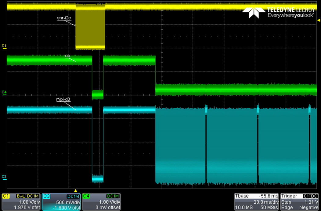
Figure 9: Smartsense sensor signal
Currently, the solution is to change the sequence of the sensor power-on and the sensor initialization. After the sensor initialize completed, then enable SoC mipi csi to resolve this problem. Please refer to the following process:
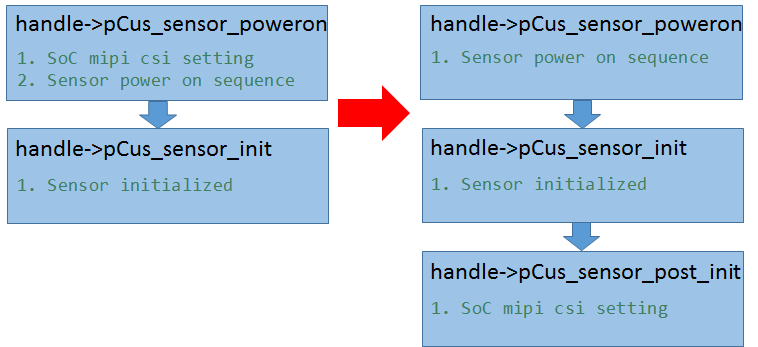
Figure 10: power on sequence flow change