SSD_Sensor Development Reference
1. Overview
1.1. Architecture
This article only introduces the basic usage process of the modules. For detailed interfaces and parameters, please refer to the API of the corresponding module.
The software block diagram is as follows, the hardware module can be called through the interface provided by limmi_xxx.so.

1.2. Commonly Used Modules
| Abbreviation | Full name | Function |
|---|---|---|
| SNR | Sensor | Obtain camera interface information, adjust resolution and frame rate, etc. |
| VIF | Video Input interface | MIPI/BT656 signal acquisition module; supports pre-scaling function, which can reduce system bandwidth occupation in specific scenarios; one sensor video input; can output one source size and one zoom size (¼) to DRAM at the same time |
| VPE | Video Process Engine | Scaling, cropping, noise reduction, image enhancement on video data |
| DIVP | Deinterlace & Video Post Process Engine | The main functions of DIVP Engine: 1. De-process Interlace data; 2. Scale and Rotate video data. |
| VENC | Video Encoder | H264/H265/MotionJpeg encoder, encodes the input YUV data, and outputs ES |
| RGN | Region Overlay&Cover | 1. Overlay supports superimposing on VPE and DIVP, such as OSD; 2. Cover supports superimposing occluded areas on VPE/DIVP. |
| IVE | Intelligent Video Engine | Provide basic operator support in image intelligent recognition algorithm |
| AI | Audio Input Interface | Acquire audio data from Micro In |
| AO | Audio Output Interface | Support PCM format audio output to Lineout/IIS Out |
| IPU | Intelligent Process Unit | Docking with Artificial Intelligence network model |
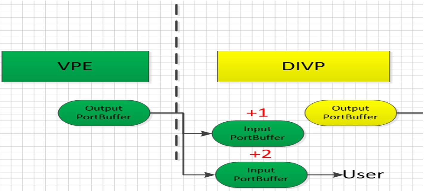
The modules are connected in series through the bind interface of sys, and the buffer transfer between the modules is as follows:

-
Input portbuffer is the OutputportBuf output by the previous level;
-
The buffer between modules is passed through sys.
Bind has two modes: frame mode and realtime mode
| Mode | Features | Use scene |
|---|---|---|
| Realtime mode | Directly connect to the hardware without occupying DRAM memory | Single sensor |
| Frame mode | Occupies multiple yuv memory. (Determined by the depth setting) | Single/multi sensor |
The depth concept of Frame mode:
Features:
-
The YUV applied for when the module is in use cannot exceed the QueueDepth set value, and it will be released immediately after use.
-
If the value of QueueDepth is set too small, when the CPU memory is insufficient, frames will be dropped because there is no buffer queue.
The module output port depth parameter can be set through the following interface (Input port buffer is the Output port buffer output by the previous level)
/*
* BufQueueDepth: The max buffers that the port can apply for at the same time, the default is 4;
* UserFrameDepth: The max buffers that the user can get at the same time through MI_SYS_ChnOutputPortGetBuf();
* BufQueueDepth >= UserFrameDepth;
*/
MI_S32 MI_SYS_SetChnOutputPortDepth(MI_SYS_ChnPort_t *pstChnPort , MI_U32 u32UserFrameDepth , MI_U32 u32BufQueueDepth);
2. Basic Modules
All the following modules depend on sys, and MI_SYS_Init() must and can only be initialized once in the entire app life cycle.
2.1. Sensor
The SNR (sensor) module can obtain the camera interface information, adjust the resolution and frame rate, etc.

Initialization:
// Set plane mode
MI_SNR_SetPlaneMode(eSnrPadId, true)
// Check the resolution supported by sensor
MI_SNR_QueryResCount(eSnrPadId, &u32ResCount)
//Check the resolution parameter corresponding to index
for(u8ResIndex = 0; u8ResIndex < u32ResCount; u8ResIndex++)
    MI_SNR_GetRes(eSnrPadId, u8ResIndex, &stRes)
// Set the output resolution
MI_SNR_SetRes(eSnrPadId, u8ChocieRes)
// Set the output frame rate
MI_SNR_SetFps(eSnrPadId, SENSOR_FPS)
// Enable sensor
MI_SNR_Enable(eSnrPadId)
// Check the current output resolution
MI_SNR_GetCurRes(eSnrPadId, &u8CurResIdx, &stCurRes)
2.2. VIF
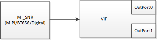
The VIF module has output but no input.
Basic usage process:
/
vifDev = (s32vifDev == 2) ? 1 : s32vifDev;
vifChn = vifDev * 4;
// Set vif device attributes
MI_VIF_SetDevAttr(vifDev, &stDevAttr)
// Enable vif device
MI_VIF_EnableDev(vifDev)
// Set output port attributes
MI_VIF_SetChnPortAttr(VifChn, VifPort, &stChnPortAttr)
// Enable output port
MI_VIF_EnableChnPort(VifChn, VifPort)
2.3. VPE
The VPE module first adjusts the image quality of the input image, including noise reduction, sharpening, brightness adjustment, etc., and then scales to a certain resolution and outputs it through each port. It also contains functions such as HDR, rotation, and cropping.
VPE has single input and multiple output, and the processing flow of different chips is not completely the same, please refer to MI VPE API to find the VPE processing logic of SSD222, as follows:
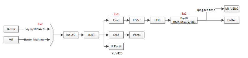
Each port can be configured with different functions. When using it, you need to configure appropriate parameters according to the internal processing process. The basic use process is as follows:
VpeChannel = s32vifDev
MI_VPE_SetChannelParam(VpeChannel, &stVpeChnParam)
MI_VPE_CreateChannel(VpeChannel, &stChannelVpeAttr)
MI_VPE_StartChannel(VpeChannel)
MI_VPE_GetPortMode(VpeChannel, VpePort, &stVpeMode)
// Change some parameter
MI_VPE_SetPortMode(VpeChannel, VpePort, &stVpeMode)
if(need crop)
    MI_VPE_SetPortCrop(VpeChannel, VpePort, &stOutCropInfo)
MI_SYS_SetChnOutputPortDepth(&stChnPort, 0, 5)
MI_VPE_EnablePort(VpeChannel, VpePort)
2.4. DIVP
The DIVP module supports image cropping, pixel format conversion, rotation, mirroring, and scaling. The input and output are single. The processing flow of different chips is not completely the same, please refer to MI DIVP API.

When enabling multiple functions of DIVP (crop, rotate, mirror, etc.) at the same time, pay attention to the order of processing.
Basic usage process:
MI_DIVP_CreateChn(u32DivpChn, &stDivpAttr)
MI_DIVP_StartChn(u32DivpChn)
MI_DIVP_SetOutputPortAttr(u32DivpChn, &stDivpOutputAttr)
2.5. DISP
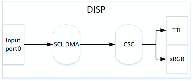
DISP is a video display unit, which mainly performs hardware splicing of the images output by the previous, and then performs color space conversion on it, and finally outputs to the display or LCD through HDMI/VGA/MIPI/TTL.
DISP module flow chart:
Basic usage process:
DispDev = 0
DispLayer = 0
// Set disp pub attribute
MI_DISP_SetPubAttr(DispDev,  &stPubAttr)
MI_DISP_Enable(DispDev)
// Set layer
MI_DISP_BindVideoLayer(DispLayer,DispDev)
MI_DISP_SetVideoLayerAttr(DispLayer, &stLayerAttr)
MI_DISP_EnableVideoLayer(DispLayer)
// Set input port attribute
MI_DISP_SetInputPortAttr(DispLayer, u8DispInport, &stInputPortAttr)
MI_DISP_EnableInputPort(DispLayer, u8DispInport)
MI_DISP_SetInputPortSyncMode(DispLayer, u8DispInport, E_MI_DISP_SYNC_MODE_FREE_RUN)
2.6. PANEL
MI_PANEL_IntfType_e eLinkType = E_MI_PNL_INTF_TTL
/* If it is a SPI panel, SPI parameters need to be issued first! */
MI_PANEL_Init(eLinkType)
// Get panel resolution parameters for dipp/disp
MI_PANEL_GetPanelParam(eLinkType, &stParamCfg)
2.7. RGN
RGN module is used to draw OSD (time, face frame, etc.) or area mask, it can be pasted on the output port of vpe or divp.

// init
MI_RGN_Init()   // Incoming palette
MI_RGN_Create()
MI_RGN_AttachToChn()
// get canvas
MI_RGN_GetCanvasInfo()
// Draw on canvas
// Update canvas
MI_RGN_UpdateCanvas()
2.8. IQSERVER
IQSERVER (Image Quality Tuning Server) is used for data communication between IQ Tool and the development board, including ISP parameter setting, image acquisition, upload/download related files and other functions. Call OPEN interface after creating the VPE channel.
/*
* width: Sensor output resolution width
* height: Sensor output resolution height
* vpeChn: VPE channel
*/
MI_IQSERVER_Open(width, height, vpeChn)
After IQ Tool connects the board to adjust the parameters, it will generate an IQ parameter file for the user app.
2.9. ISP
The ISP module analyzes and processes the data input by the Video source, sets related video parameters, and adjusts the Camera to realize black level correction, lens correction, 3A, 2D/3D noise reduction, CCM, Gamma and other functions.
The app of ordinary users will only use the interface it provides to load the adjusted IQ parameter file.
The process is as follows:
do
{
    MI_ISP_IQ_GetParaInitStatus(Vpechn,&bstatus)
    if(bstatus.stParaAPI.bFlag != 1)
    {
        // Check exit conditions to avoid endless loops
        if(timeout)
        {
            break;
        }
        continue;
    }
    // pConfigPath is the path of the adjusted IQ parameter file
    MI_ISP_API_CmdLoadBinFile(Vpechn, (char*)pConfigPath,  1234)
}
while();
3. Dual Sensor Application
3.1. Basic Data Flow
Common user scenarios:
Two sensors (RGB+IR) respectively output the image to the algorithm for processing, and output through RTSP. Send RGB Sensor to LCD to display.
Add a switch to switch the LCD display, you can switch sensor-0, sensor-1 or black screen (input black data through Inject Task, in order to display GUI normally when there is no image)
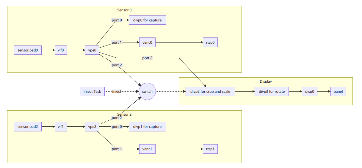
When the DIVP is not enough in use, you can put crop/scale/rotate in vpe0 for processing, and divide it into the DIVP of the Display part for processing to remove interface coupling, so that users can more flexibly "switch horizontal to vertical display" Or "switch vertical to horizontal display".
3.2. DIVP Snapshot
Obtain the divp output port descriptor through the sys module interface, use this interface to read the output data of divp.
The process is as follows:
MI_SYS_GetFd(&stChnPort, &s32Fd)
MI_SYS_SetChnOutputPortDepth(&stDivpChnOutput, 1, 5)
while(1)
{
        FD_ZERO(&read_fds);
        FD_SET(s32Fd, &read_fds);
        TimeoutVal.tv_sec  = 1;
        TimeoutVal.tv_usec = 0;

        /*Waiting for frame*/
        s32Ret = select(s32Fd + 1, &read_fds, NULL, NULL, &TimeoutVal);
        if(s32Ret > 0 && FD_ISSET(s32Fd, &read_fds))
        {
            /* Get a frame from divp */
            if(MI_SUCCESS  == MI_SYS_ChnOutputPortGetBuf(&stDivpChnOutput, &stBufInfo, &hHandle))
            {
            #if 0
                if(stBufInfo.stFrameData.ePixelFormat == E_MI_SYS_PIXEL_FRAME_YUV_SEMIPLANAR_420)
                {
                    //memcpy(dstbuf, (char *)stBufInfo.stFrameData.pVirAddr[0], stBufInfo.stFrameData.u16Width * stBufInfo.stFrameData.u16Height * 3 >> 1);
                }
                else if((stBufInfo.stFrameData.ePixelFormat  == E_MI_SYS_PIXEL_FRAME_YUV422_YUYV))
                {
                    //memcpy(dstbuf, stBufInfo.stFrameData.pVirAddr[0], stBufInfo.stFrameData.u16Width * stBufInfo.stFrameData.u16Height * 2);
                }

                else if((stBufInfo.stFrameData.ePixelFormat  == E_MI_SYS_PIXEL_FRAME_RGB565))
                {
                    //memcpy(dstbuf, (char *)stBufInfo.stFrameData.pVirAddr[0], stBufInfo.stFrameData.u16Width * stBufInfo.stFrameData.u16Height * 2);
                }
                else if(stBufInfo.stFrameData.ePixelFormat  == E_MI_SYS_PIXEL_FRAME_ARGB8888)
                {
                    //memcpy(dstbuf, (char *)stBufInfo.stFrameData.pVirAddr[0], stBufInfo.stFrameData.u16Width * stBufInfo.stFrameData.u16Height * 4);
                }
            #endif
                /*Free frame*/
                s32Ret = MI_SYS_ChnOutputPortPutBuf(hHandle);
                if(s32Ret != MI_SUCCESS)
                {
                    ST_ERR("MI_SYS_ChnOutputPortPutBuf failed.s32Ret:0x%x !\n", s32Ret);
                }

            }
            else
            {
                ST_ERR("MI_SYS_ChnOutputPortGetBuf failed!\n");
            }
        }
}
MI_SYS_CloseFd(s32Fd)
3.3. RGN and FB Binding Location Selection
RGN and FB can be bound to the output port of VPE or DIVP, and the data stream behind the binding position will have bound data. The binding position is selected according to the attributes of the output port (mainly the resolution parameter) and the influence range of the data stream.
For example:
-
Draw the face frame through RGN, the image recognized by the algorithm is the original size, and the face frame coordinates are calculated based on the original image. To display the face frame to the correct position, please attach RGN to port2 of vpe0;
-
When LCD switch vertical to horizontal display, when drawing GUI on FB, FB should be bound to the output port of dipp2 (for crop and scale), because the image output by this port is the one that is actually displayed on the LCD. When rotating, the GUI will also rotate to achieve the desired effect.
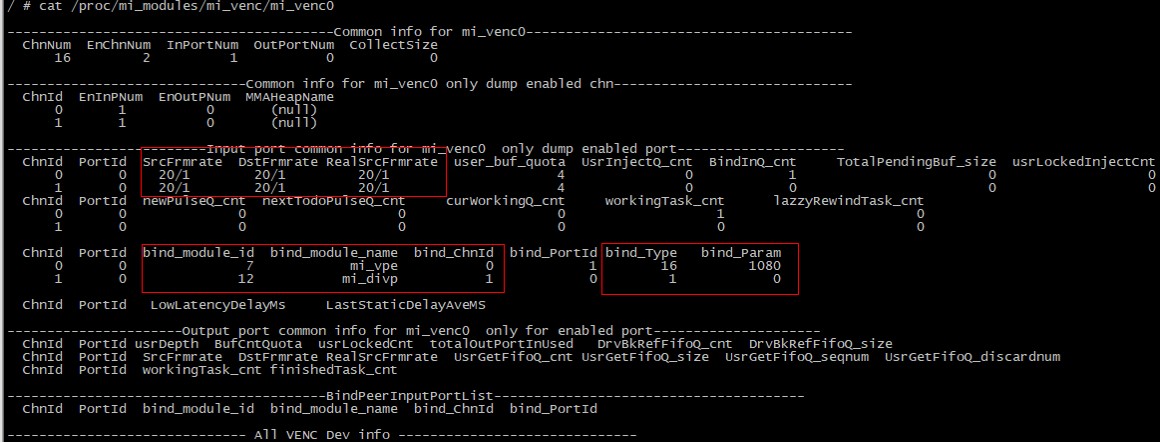
4. Debug Information
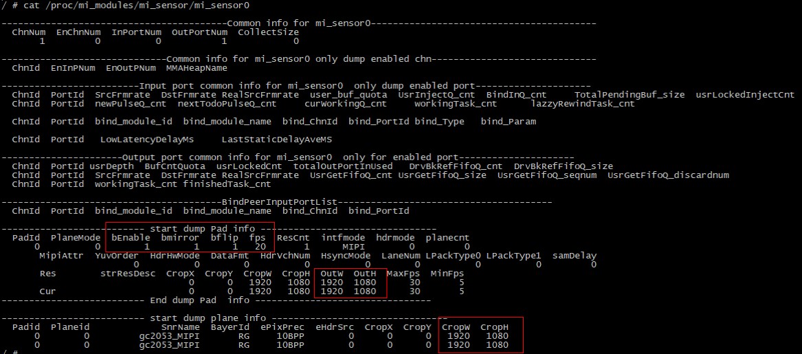
You can view the debug information currently running under the subfolders of each module in the /proc/mi_modules/ directory.
-
Sensor debug
-
Vpe debug

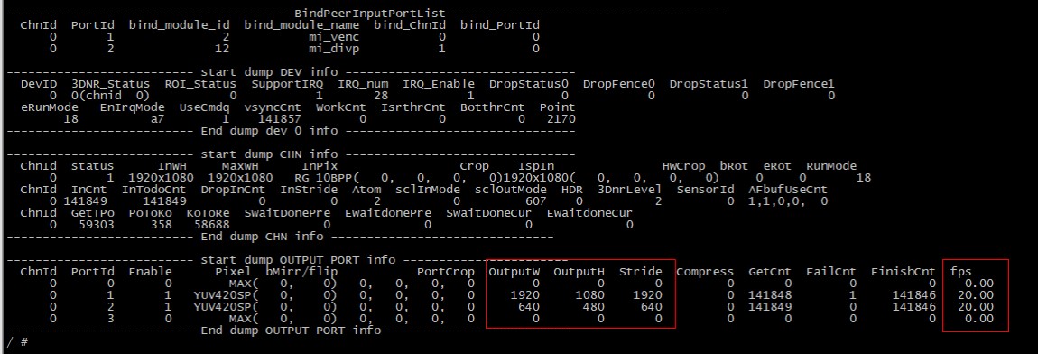
-
Divp debug

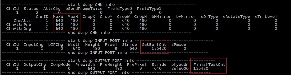
-
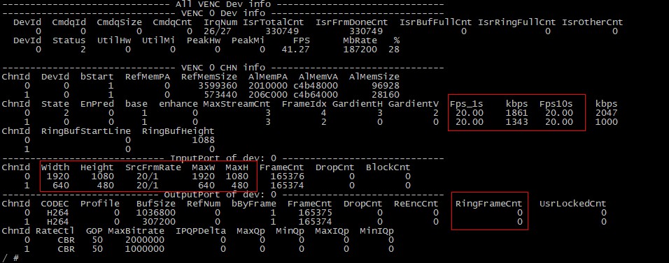
Venc debug