SSD_Sensor Usage Reference
1. MIPI SENSOR configuration reference
1.1. MIPI pin configuration
The pins that the Mipi Sensor needs to configure are mainly mipi data & clk, mclk, powerdown, reset, i2c as shown below:
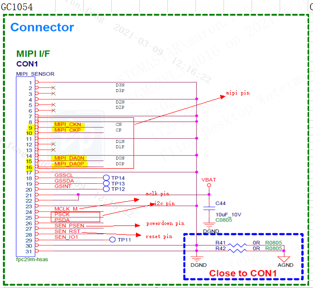
1.1.1. Mipi data & clk pin configuration
First, check the hwchecklist table to see which set of mipi pins are currently used. The following is the public version with two GC1054 1lane sensor selected pin:
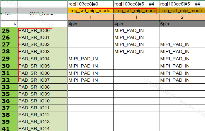
So configure the mode of sensor0 and sensor1 as 1 in kernel\arch\arm\boot\dts\pioneer3.dtsi:
1.  vif: vif {
2.      compatible = "sstar,vif";
3.      status = "ok";
4.      reg = <0x1F263200 0x600>, <0x0 0x0>, <0x0 0x0>, <0x0 0x0>, <0x0 0x0>, <0x0 0x0>, <0x1F203C00 0x200>, <0x1F227200 0x200>, <0x1F207000 0x200>, <0x1F000000 0x400000>, <0x1F207C00 0x200>;
5.      //clocks = <&CLK_sr_mclk>;
6.      interrupts = <GIC_SPI INT_IRQ_VIF IRQ_TYPE_LEVEL_HIGH>;
7.      // Config sensor 0 pad mux
8.
9.      vif_sr0_par_mode = <3>;
10.     vif_sr0_parallel_rst_mode = <1>;
11.     vif_sr0_parallel_pdn_mode = <1>;
12.     vif_sr0_mclk_mode = <1>;
13.     vif_sr0_mipi_mode = <1>;
14.     vif_sr0_mipi_ctrl_mode = <1>;
15.     vif_sr0_bt656_mode = <4>;
16.     // Config sensor 1 pad mux
17.     vif_sr1_par_mode = <0>;
18.     vif_sr1_mipi_mode = <1>;
19.     vif_sr1_mipi_ctrl_mode = <1>;
20.     vif_sr1_bt656_mode = <2>;
21. };
After the configuration is complete, you can check whether the configuration is successful by reading the following registers:
Sensor0: /customer/riu_r 0x103c 0x74 //Check whether the value corresponding to bit0 is the value configured by vif_sr0_mipi_mode
Sensor1: /customer/riu_r 0x103c 0x74 //Check whether the value corresponding to bit4~5 is the value configured by vif_sr1 _ mipi_mode
Note: This register will not be automatically configured when booting. It will be configured when the vif is initialized, so the correct value must be read after the vif is initialized.
If the clk and data of mipi on the sensor side are inconsistent with those from the chip, you can configure it through the csi of dts:
csi {
/* mipi0 2lane setting /
/ Config max lane number /
csi_sr0_lane_num = <1>; // 1: for GC1054 1 lane; 2: for imx307 2 lane
/ Config lane selection /
csi_sr0_lane_select = <1 0 2 3 4>; //
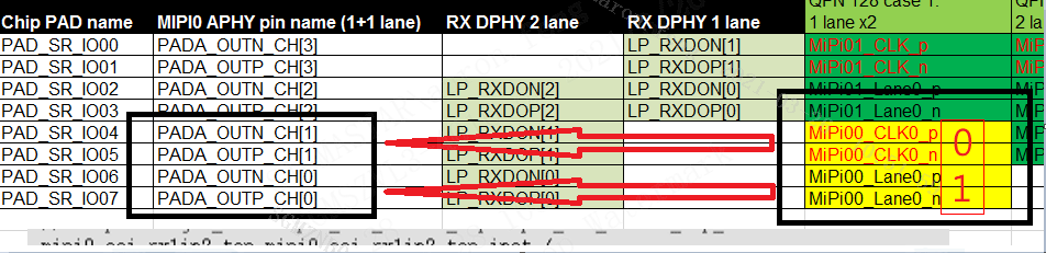
Among them, csi_sr0_lane_select is an array in the corresponding driver. The elements in the array are the coordinates corresponding to PADA_OUT_CH. The five positions in csi_sr0_lane_select correspond to the MIPI CSI \< CLK Lane0 Lane1 Lane2 Lane3>
Take the gc1054 connected to 1lane as an example, you only need to configure clk and lane0, the corresponding clk and lane0 index is 1 and 0 respectively, so the value of csi_sr0_lane_select is \< 1 0 xx x> ;
However, the five positions in csi_sr0_lane_pn_swap correspond to PADA_OUT_\< CH0 CH1 CH2 CH3 CH4> whether P/N crossover is required, instead of the order of the five groups of lanes \< CLK Lane0 Lane1 Lane2 Lane3>, pay attention to the fixed correspondence of the five indexes of swap PADA_OUT_CH, does not change with the change of the lane order of select.
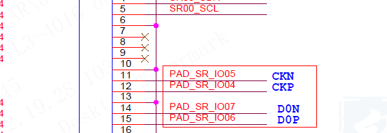
As shown above, the original chip PAD_SR_IO07 needs to be connected to mipi The P signal is actually connected to the N signal of the sensor, so the value of csi_sr0_lane_pn_swap should also be filled with 1 for swap.
If there is no csi information configured in dts, the default 2lane configuration of the driver is as follows:
csi {
    /* mipi0 2lane setting */
    /* Config max lane number */
    csi_sr0_lane_num = <2>; // 1: for GC1054 1 lane; 2: for imx307 2 lane
    /* Config lane selection */
    csi_sr0_lane_select = <1 0 2 3 4>;
    csi_sr1_lane_select = <1 0 2 3 4>;
    /* Config lane P/N swap */
    csi_sr0_lane_pn_swap = <1 1 1 1 1>;
    csi_sr1_lane_pn_swap = <1 1 1 1 1>;
};
1.1.2. Mipi mclk & powerdown & reset pin configuration
First confirm with the hardware which set of pins to use, and then find the mode used in hwchecklist. The following is the pin used by the public version to connect two gc1054 sensors:
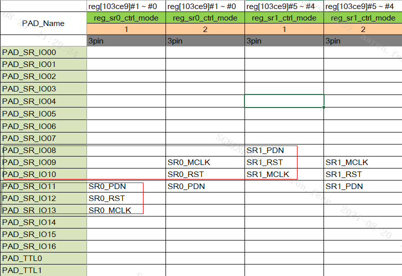
So configure the mode of sensor0 and sensor1 to 1 in kernel\arch\arm\boot\dts\pioneer3.dtsi:
22. vif: vif {
23.     compatible = "sstar,vif";
24.     status = "ok";
25.     reg = <0x1F263200 0x600>, <0x0 0x0>, <0x0 0x0>, <0x0 0x0>, <0x0 0x0>, <0x0 0x0>, <0x1F203C00 0x200>, <0x1F227200 0x200>, <0x1F207000 0x200>, <0x1F000000 0x400000>, <0x1F207C00 0x200>;
26.     //clocks = <&CLK_sr_mclk>;
27.     interrupts = <GIC_SPI INT_IRQ_VIF IRQ_TYPE_LEVEL_HIGH>;
28.     // Config sensor 0 pad mux
29.
30.     vif_sr0_par_mode = <3>;
31.     vif_sr0_parallel_rst_mode = <1>;
32.     vif_sr0_parallel_pdn_mode = <1>;
33.     vif_sr0_mclk_mode = <1>;
34.     vif_sr0_mipi_mode = <1>;
35.     vif_sr0_mipi_ctrl_mode = <1>;
36.     vif_sr0_bt656_mode = <4>;
37.     // Config sensor 1 pad mux
38.     vif_sr1_par_mode = <0>;
39.     vif_sr1_mipi_mode = <1>;
40.     vif_sr1_mipi_ctrl_mode = <1>;
41.     vif_sr1_bt656_mode = <2>;
42. };
After the configuration is complete, you can check whether the configuration is successful by reading the following registers:
Sensor0: /customer/riu_r 0x103c 0x74 //Check whether the value corresponding to bit8~9 is the value configured by vif_sr0_mipi_ctrl_mode
Sensor1: /customer/riu_r 0x103c 0x74 //Check whether the value corresponding to bit12~13 is the value configured by vif_sr1_mipi_ctrl_mode
==Note: This register will not be automatically configured at boot, it will be configured when the vif is initialized, so the correct value must be read after the vif is initialized. ==
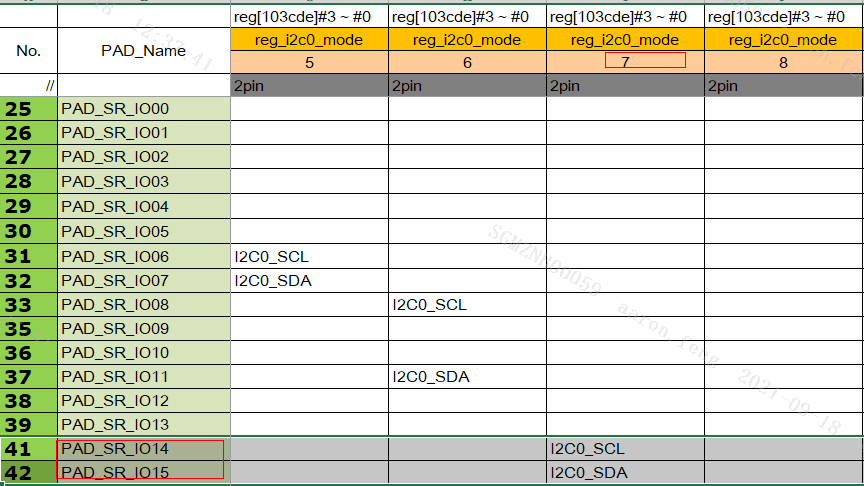
1.1.3. Mipi i2c configuration
First, confirm with the hardware which group of i2c the sensor is using, and then configure the i2c bus of the sensor in the corresponding dts, the following is the configuration of the public board to connect two gc1054 sensors to share one i2c0:
1.  sensorif: sensorif {
2.      compatible = "sigma,sensorif";
3.      sensorif_grp0_i2c = <0>;
4.      sensorif_grp1_i2c = <0>;
5.  };
The configuration of the specific pin of I2c is configured in the dtsi of the corresponding padmux under the kernel\arch\arm\boot\dts\:
1.  //i2c0_mode_11
2.  <PAD_SR_IO14               PINMUX_FOR_I2C0_MODE_7       MDRV_PUSE_I2C0_SCL>,
3.  <PAD_SR_IO15               PINMUX_FOR_I2C0_MODE_7       MDRV_PUSE_I2C0_SDA>,
After the configuration is completed, you can turn on the machine and confirm whether the matching is successful by reading the following registers:
I2c0: /customer/riu_r 0x103c 6f //whether bit0~3 is the value of the corresponding mode
I2c1: /customer/riu_r 0x103c 6f //Whether bit4~7 is the value of the corresponding mode
1.2. Sensor driver import
The Sensor driver mainly contains the slave address, lanenum and initialization parameters of the sensor. After getting the sensor driver, put it in the sdk\driver\SensorDriver\drv\src directory, make clean; make can get the ko of the corresponding sensor.
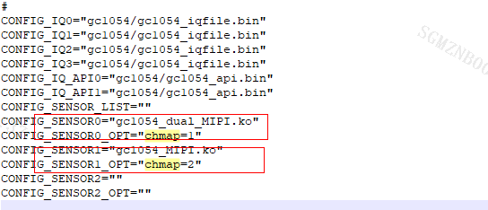
In the scenario of multiple sensors, the parameter chmap of insmod ko is used to determine which sensor the sensor driver corresponds to. The corresponding relationship is as follows:
Sensor N $ \rightarrow $ chmap: 2^N
Chmap are configured in the corresponding config file under project\configs\defconfigs:
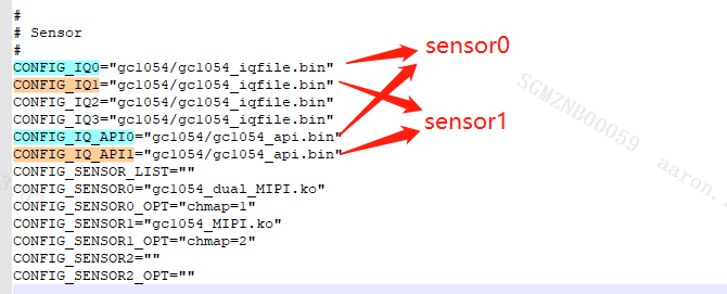
1.3. Sensor iq file import
At present, the effect of sensor images is mainly adjusted by two files, iqfile and iq api, which are placed in the following directories:
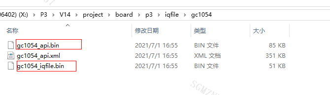
Among them, the iqfile is the common part and generally will not be changed. The iq engineer mainly adjusts the iq api file to adjust the effect of the image. These two files are configured in the config file corresponding to project\configs\defconfigs:
1.4. Demo usage reference
Sensor-related SDK modules are mainly sensor & vif & vpe. The points to be noted are as follows.
1.4.1. Sensor
The Sensor module mainly obtains sensor information from the sensor driver for use by other modules and configures the resolution of the sensor.
1.  DBG_INFO("i[%d]\n", i);
2.  //Choose sensor ID
3.  eSNRPad = (MI_SNR_PAD_ID_e)i;
4.  //set HDR mode
5.  if(pstConfig->s32HDRtype > 0)
6.  {
7.      STCHECKRESULT(MI_SNR_SetPlaneMode(eSNRPad, TRUE));
8.  }
9.  else
10. {
11.     STCHECKRESULT(MI_SNR_SetPlaneMode(eSNRPad, FALSE));
12. }
13. //Query all resolutions supported by sensor driver
14. STCHECKRESULT(MI_SNR_QueryResCount(eSNRPad, &u32ResCount));
15. for(u8ResIndex = 0; u8ResIndex < u32ResCount; u8ResIndex++)
16. {
17.     MI_SNR_GetRes(eSNRPad, u8ResIndex, &stRes);
18.     DBG_INFO("eSNRPad[%d], index[%d], Crop(%d,%d,%d,%d), outputsize(%d,%d), maxfps[%d], minfps[%d], ResDesc[%s] \n",
19.     eSNRPad,
20.     u8ResIndex,
21.     stRes.stCropRect.u16X, stRes.stCropRect.u16Y, stRes.stCropRect.u16Width,stRes.stCropRect.u16Height,
22.     stRes.stOutputSize.u16Width, stRes.stOutputSize.u16Height,
23.     stRes.u32MaxFps,stRes.u32MinFps,
24.     stRes.strResDesc);
25. }
26.
27. DBG_INFO("eSNRPad[%d], cnt[%d]resolutions, choice[%d] \n", eSNRPad, u32ResCount, pstConfig->u8SNRChocieRes);
28. #if 0
29. do
30. {
31.     scanf("%d", &u32ChocieRes);
32.     ST_Flush();
33.     MI_SNR_QueryResCount(E_MI_SNR_PAD_ID_0, &u32ResCount);
34.     if(u32ChocieRes >= u32ResCount)
35.     {
36.         DBG_INFO("choice err res %d > =cnt %d\n", u32ChocieRes, u32ResCount);
37.     }
38. }while(u32ChocieRes >= u32ResCount);
39. DBG_INFO("You select %d res\n", u32ChocieRes);
40. #else
41.
42. u32ChocieRes = pstConfig->u8SNRChocieRes;
43. #endif
44. //gc1054 default set mirror/flip = 1
45. if(ST_Sensor_Type_GC1054 == pstConfig->enSensorType)
46. {
47.     STCHECKRESULT(MI_SNR_SetOrien(eSNRPad, 1, 1));
48. }
49. //Select the resolution you want to output
50. STCHECKRESULT(MI_SNR_SetRes(eSNRPad,u32ChocieRes));
51. //enable sensor
52. STCHECKRESULT(MI_SNR_Enable(eSNRPad));
53. //Get the resolution, frame rate and pixformat information output by the sensor
54. STCHECKRESULT(MI_SNR_GetPadInfo(eSNRPad, &stPadInfo));
55. STCHECKRESULT(MI_SNR_GetPlaneInfo(eSNRPad, 0, &stSnrPlaneInfo));
56.
57. g_u32CapWidth = stSnrPlaneInfo.stCapRect.u16Width;
58. g_u32CapHeight = stSnrPlaneInfo.stCapRect.u16Height;
59. u32CapWidth = stSnrPlaneInfo.stCapRect.u16Width;
60. u32CapHeight = stSnrPlaneInfo.stCapRect.u16Height;
61. eFrameRate = E_MI_VIF_FRAMERATE_FULL;
62. ePixFormat = (MI_SYS_PixelFormat_e)RGB_BAYER_PIXEL(stSnrPlaneInfo.ePixPrecision, stSnrPlaneInfo.eBayerId);
1.4.2. Vif
The Vif module mainly configures the resolution, PixFormat, and frame rate of the incoming image from the sensor. It should be noted that the corresponding relationship between the channel num of vif and the vif dev is:
Dev N $ \rightarrow $ Channel 4 * N
1.   //Select the Vif device, channel and port to be initialized
2.   u32VifDevId = i;
3.   u32VifChnId = i * 4;
4.   u32VifPortId = 0;
5.   eVifHdrType = (MI_VIF_HDRType_e)pstConfig->s32HDRtype;
6.  //Select frame or realtime mode. Realtime mode only supports the scene of one sensor
7.   eVifWorkMode = u8SensorNum > 1 ? E_MI_VIF_WORK_MODE_RGB_FRAMEMODE : E_MI_VIF_WORK_MODE_RGB_REALTIME;
8.   DBG_INFO("VIF:DevId[%d] ChnId[%d] PortId[%d], eVifWorkMode[%d]\n", u32VifDevId, u32VifChnId, u32VifPortId, eVifWorkMode);
9.  //enable vif
10.  STCHECKRESULT(ST_Vif_EnableDev(u32VifDevId, eVifWorkMode, eVifHdrType, &stPadInfo));
11.
12.  memset(&stVifPortInfoInfo, 0, sizeof(ST_VIF_PortInfo_T));
13.  stVifPortInfoInfo.u32RectX = stSnrPlaneInfo.stCapRect.u16X;
14.  stVifPortInfoInfo.u32RectY = stSnrPlaneInfo.stCapRect.u16Y;
15.  stVifPortInfoInfo.u32RectWidth = u32CapWidth;
16.  stVifPortInfoInfo.u32RectHeight = u32CapHeight;
17.  stVifPortInfoInfo.u32DestWidth = u32CapWidth;
18.  stVifPortInfoInfo.u32DestHeight = u32CapHeight;
19.  stVifPortInfoInfo.eFrameRate = eFrameRate;
20.  stVifPortInfoInfo.ePixFormat = ePixFormat;
21.  //Set the position, resolution, frame rate and pixformat of the output image of port corresponding to Vif
22.  STCHECKRESULT(ST_Vif_CreatePort(u32VifChnId, u32VifPortId, &stVifPortInfoInfo));
23.  //Start the corresponding port
24.  STCHECKRESULT(ST_Vif_StartPort(u32VifDevId, u32VifChnId, u32VifPortId));
1.4.3. Vpe
The Vpe module is mainly to set the resolution of the output image, PixFormat.
1.   //Select the dev, CHN, port to initialize
2.   u32VpeDevId = 0;
3.   u32VpeChnId = i;
4.   u32VpePortId = 0;
5.   memset(&stVpeChannelInfo, 0, sizeof(ST_VPE_ChannelInfo_T));
6.   eVpeHdrType = (MI_VPE_HDRType_e)pstConfig->s32HDRtype;
7.   stVpeChannelInfo.u16VpeMaxW = u32CapWidth;
8.   stVpeChannelInfo.u16VpeMaxH = u32CapHeight;
9.   stVpeChannelInfo.u32X = 0;
10.  stVpeChannelInfo.u32Y = 0;
11.  stVpeChannelInfo.u16VpeCropW = 0;
12.  stVpeChannelInfo.u16VpeCropH = 0;
13.  stVpeChannelInfo.eRunningMode = u8SensorNum > 1 ? E_MI_VPE_RUN_CAM_MODE : E_MI_VPE_RUN_REALTIME_MODE;
14.  stVpeChannelInfo.eFormat = ePixFormat;
15.  stVpeChannelInfo.e3DNRLevel = pstConfig->en3dNrLevel;
16.  stVpeChannelInfo.eHDRtype = eVpeHdrType;
17.  stVpeChannelInfo.bRotation = FALSE;
18.  if(stVpeChannelInfo.eRunningMode == E_MI_VPE_RUN_DVR_MODE)
19.  {
20.      stVpeChannelInfo.eBindSensorId = E_MI_VPE_SENSOR_INVALID;
21.  }
22.  else
23.  {
24.      stVpeChannelInfo.eBindSensorId = (MI_VPE_SensorChannel_e)(eSNRPad+1);
25.  }
26.  DBG_INFO("VPE:DevId[%d] ChnId[%d] PortId[%d],eRunningMode[%d]\n", u32VpeDevId, u32VpeChnId, u32VpePortId, stVpeChannelInfo.eRunningMode);
27. //Set the position, resolution, crop and pixformat information of the corresponding channel output image
28.  STCHECKRESULT(ST_Vpe_CreateChannel(u32VpeChnId, &stVpeChannelInfo));
29.  STCHECKRESULT(ST_Vpe_StartChannel(u32VpeChnId));
If you need to adjust the image effect through the iq tool, you also need to call MI_IQSERVER_Open to open the corresponding vpe channel. For specific use, refer to the Demo source code.
1.  //Select the VPE channel to be adjusted
2.  u32VpeDevId = 0;
3.  u32VpeChnId = i;
4.  u32VpePortId = 0;
5.  //open ip server
6.  memset(&stVifPortInfo, 0, sizeof(MI_VIF_ChnPortAttr_t));
7.  STCHECKRESULT(MI_VIF_GetChnPortAttr(u32VpeChnId, u32VpePortId, &stVifPortInfo));
8.  STCHECKRESULT(MI_IQSERVER_Open(stVifPortInfo.stDestSize.u16Width, stVifPortInfo.stDestSize.u16Height, u32VpeChnId));