PQ TOOL REFERENCE
1. PQ Tool Connection
1.1. Connect And Write Parameters
-
Click PQ tool

Fig 1-1 PQ tool icon
-
Disable serial port printing
For connecting the tool and serial port, please disable serial port printing and disconnect it.
Take Ikayaki series as an example: Enter 11111 in the serial port print window to stop the serial port printing information. Then disconnect.
-
Chip select
Select the chip type. Ikayaki select SsInfinity Series.

Fig 1-2 Chip type options
-
Tool config
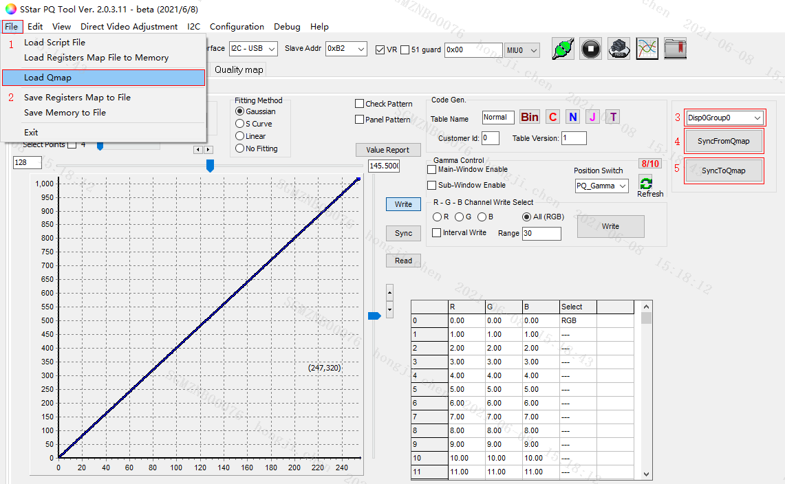
Fig 1-3 Config and connection
First select chip series, and then click the icon to connect. If the icon is green, it is successful. If it prompts an error, please make sure that the serial port printing information is disabled and disconnected, and then try again.
-
Read register value
-
Switch to the corresponding band.
-
Enter 0x101e in the box and press Enter.
-
Click Read Bank.
-
Check the register value on the right, all zeros or all ffs indicate that the tool is not connected correctly.
-
The reference value is shown in Fig 1-5.

Fig 1-4 Read register value
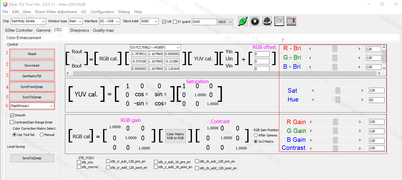
Fig 1-5 Bank interface
-
-
Save the modified parameters to the board
-
Open the QMAP table to page1920 .
-
Click
C-code generatorto generate a folder named 1920 in the root directory, as shown in Figure 1-6. -
Write
PQConfig.iniThe format is as follows:
[PQ_PATH]

default = "/config/PQ.bin"
-
Pack this
iniinto the config partition, and putPQ.binin the 1920 folder in the specified path ofini, which can be changed as required, and the path ofPQConfig.inishould also be modified.
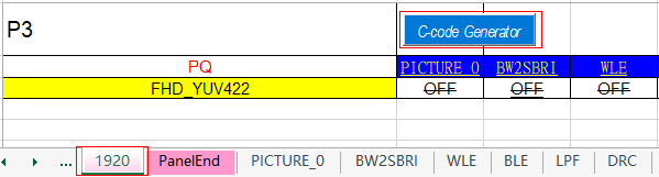
Fig 1-6 QMAP generate PQ.bin
-
2. Module Function Usage
2.1. Gamma
-
Open the gamma subpage.
-
Select
Main-Window Enable. -
Set to adjust the R/G/B curve individually or synchronous.
-
Switch to Write, click the Write button on the right to write the debugged gamma curve to the board, which can be seen directly on the screen.
-
Switch to Read, click the Read button on the right to view the current gamma curve displayed on the tool.
-
Select Points
Automatically set the debugging node, you can also manually debug the gamma curve, and add nodes at different locations.
-
SyncFromQmap
Load the gamma parameter in the OFF column of GAMMA_0_R/G/B in Qmap.
-
SyncToQmap
Write the parameters debugged on the tool into GAMMA_0_R/G/B in the Qmap table.
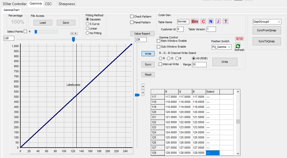
Fig 2-1 Gamma debug interface
2.2. CSC
-
Switch to CSC.
-
Reset
Initialize the current parameters.
-
Download
Write the current debugging interface parameters to the board.
-
Restore To UI Value
Read the current value of the board and display it on the tool.
-
SyncFromQmap
Write the parameters of the current group in the QMAP table to the board.
-
SyncToQmap
Write the debugging parameters to the current group in the Qmap table.
-
Save Setting
Save the current parameter.
-
Load Setting
Import the saved parameter and display it to the tool.
-
RGB bri
RGB brightness
-
Sat
saturation, adjust the overall saturation.
-
Hue
Adjust the overall tone.
-
RGB gain
White Balance gain。
-
Contrast
Adjust the overall contrast.

Fig 2-2 CSC interface
2.3. Sharpness
-
2D Peaking Enable
Enable sharpness.
-
Peaking_Bank_refresh
Read and refresh the parameters of the current evaluation board and display them on the interface.
-
Save Peaking to file
Save the sharpness parameters of the current board to
Sharp_Parameter.txt. -
Save Setting
Save the current parameters to the local.
-
Load Setting
Import the locally saved parameters and display them on the tool without writing to the board.
-
SyncFromQmap
Write the data of the current group on the peaking page of the QMAP table into the board.
-
SyncToQMAP
Write the currently debugged parameters of the board into the QMAP table.
-
HVB Band B01
Adjust the sharpness intensity of B01 in the horizontal direction.
-
HVB Band B02
Adjust the sharpness intensity of B02 in the horizontal direction.
-
Coring Threshold1
Weakened the burr phenomenon after Band B01 strengthened sharpness.
-
Coring Threshold2
Weakened the burr phenomenon after Band B02 strengthened sharpness.
Fig 2-3 Sharpness
3. Note
The above is for the Ikayaki platform, the unspecified modules can be operated but the writing is invalid.