SSD_GPIO REFERENCE
1. Overview
1.1. Summary
GPIO adopts a standard LINUX framework and can use a unified interface to operate gpio.
1.2. GPIO NUM And PAD Correspondence Table
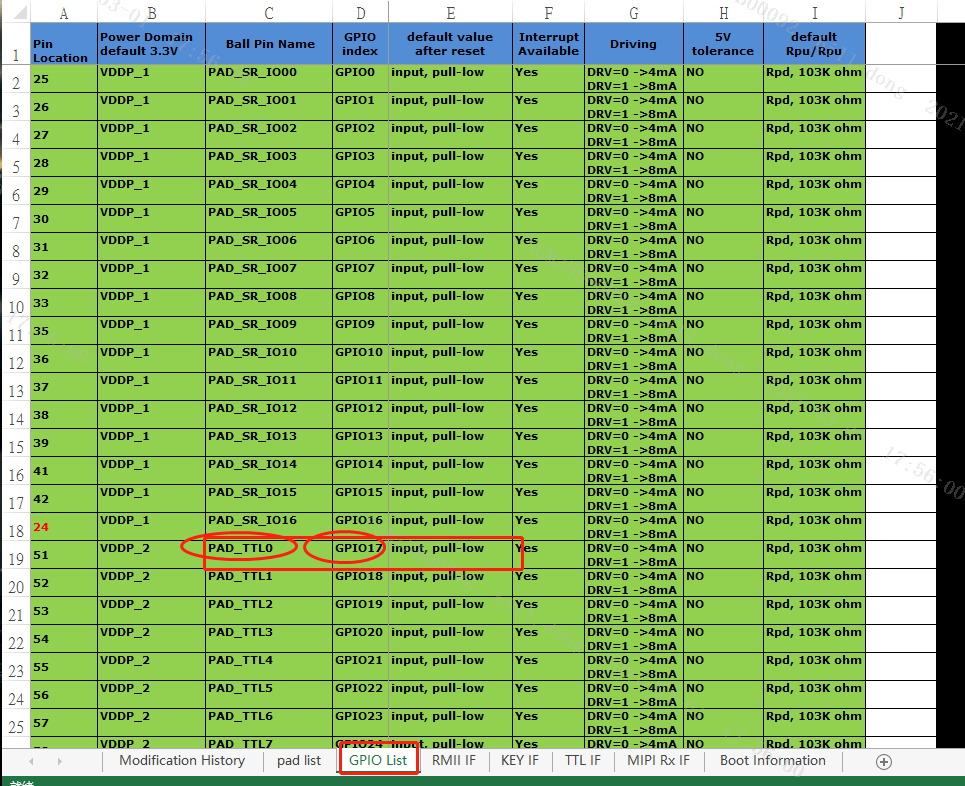
Please check the PAD name of the GPIO on the hardware circuit diagram, look up the table to find the corresponding num.
A GPIO on the hardware circuit diagram is PAD_TTL0, and the corresponding num=17 for operating this GPIO.
Please check the GPIO List of SSD2xx_HW CheckList.xlsx for the open GPIOs.
Table 1-1
2. GPIO Using In Kernel
2.1. Apply AS A GPIO Port
-
Purpose
Create the port as GPIO.
-
Syntax
int gpio_request(unsigned gpio, const char *label)
-
Parameter
Parameter Name Description gpio Gpio num label Specific name -
Return Value
Return Value Description 0 Successful. Other Failed.
2.2. Set As Input
-
Purpose
Mark gpio as input.
-
Syntax
int gpio_direction_input(unsigned gpio);
-
Parameter
Parameter Name Description gpio Gpio num -
Return Value
Return Value Description 0 Successful. Other Failed.
2.3. Set As Output
-
Purpose
Mark gpio as output.
-
Syntax
int gpio_direction_output(unsigned gpio, int value);
-
Parameter
Parameter Name Description gpio Gpio num value Output value -
Return Value
Return Value Description 0 Successful. Other Failed.
2.4. Get Input Level
-
Purpose
Get the level of the input pin.
-
Syntax
int gpio_get_value(unsigned gpio);
-
Parameter
Parameter Name Description gpio Gpio num -
Return Value
Return Value Description Int Electrical level value
2.5. Get Output Level
-
Purpose
Get the level of the output pin.
-
Syntax
void gpio_set_value(unsigned gpio, int value);
-
Parameter
Parameter Name Description gpio Gpio num value Output value -
Return Value
Return Value Description 0 Successful. Other Failed.
2.6. Register GPIO Interrupt
For registering gpio interrupt in kernel, please refer to Kernel/drivers/sstar/gpio/test/gpio_irq_test.c.
| Function name | Description |
|---|---|
| gpio_request | Apply to use gpio |
| gpio_direction_input | Configure gpio as input |
| gpio_to_irq | Get the interrupt number |
| request_irq | Register interrupt function |
| gpio_test_isr | Interrupt service function |
| free_irq | Release interrupt |
| gpio_free | Release gpio |
Test:
Compile and generate gpio_irq.ko under the kernel, use insmod to load the module, change on the falling edge by default, and the interrupt service function handles interrupt events.
3. GPIO using In User Space
User space access gpio, that is, access gpio through the sysfs interface.
The following are three types of files in the /sys/class/gpio directory:
--export/unexport file
--gpioN refers to the specific gpio pin
--gpio_chipN refers to the specific gpio controller
It must be known that the above interfaces do not have standard device files and their links.

3.1. export/unexport File Interface
/sys/class/gpio/export is write only.
When there is no kernel code to apply for a gpio port, the user program can apply to the kernel to export the control of this gpio to user space by writing the gpio number.
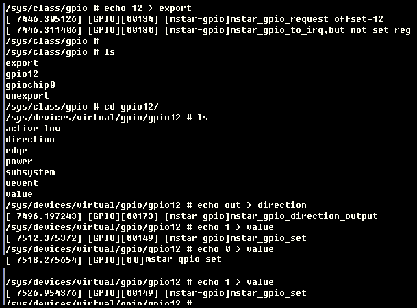
For example: the user applies for the GPIO command numbered 12:
echo 12 > export
The above operation will create a node gpio12 for gpio num12. At this time, a gpio12 directory will be generated under the /sys/class/gpio, as shown below:

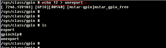
/sys/class/gpio/unexport is the opposite of export.
For example, remove the node gpio12:
echo 12 > unexport
3.2. /sys/class/gpio/gpioN
Refers to a specific gpio port, which has the following attributes files:
direction: The direction of the gpio port, the read result is in or out. You can also write to the file. When writing out, the gpio is set to output and the level defaults to low. When writing low or high, it can not only be set to output but also can set the specified output level. If the kernel or kernel code do not support, this attribute will not exist. For example, if the kernel calls gpio_export(N,0), it means that the kernel is unwilling to modify the gpio port direction attribute.
value: The level of the gpio pin, 0: low level, 1: high level; If gpio is configured as an output, this value is writable, and any non-zero value is output as a high level. If a pin is configured as an interrupt, you can call the poll(2) function to monitor. After the interrupt is triggered, poll(2) will be returned.
3.3. Code
Non-interrupt mode
Provide gpio_main.c for user space that can operate GPIO by sysfs interface.
Write:
int ss_gpio_set_value(unsigned int gpio, unsigned int value)
Pass in the gpio number to be written, input 1/0, control high/low level;
Read:
int ss_gpio_get_value(unsigned int gpio, unsigned int *value)
Pass in the gpio number to be written, and get the current level status.
Compile the sample code to generate gpio_main, and execute the bin file.
# arm-linux-gnueabihf-gcc –o gpio_main gpio_main.c
Run the cmd in the shell to test gpio:
# ./gpio_main input
# ./gpio_main output 1
Provide gpio_mmap.c for user space to access registers and operate gpio by mmap. User needs to check the GPIO_Mapping_Table to confirm the bank base address and offset address of gpio. Take PAD_GPIO0 as an example.
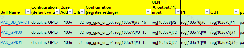
The bank base address is 0x103E, the offset address is 0x3D, BIT3 enables gpio mode, BIT2 configures the gpio direction, BIT1 controls the output level, and the value of BIT0 is the input level state.
4. BOOT Use GPIO
4.1. CMD: gpio -Config gpio port
Usage:

gpio (for 2nd parameter, you must type at least 3 characters)

gpio output <gpio#> <1/0>  : ex: gpio output 69 1

gpio input/get <gpio#>     : ex: gpio input 10  (gpio 10 set as input)

gpio toggle <gpio#>        : ex: gpio tog 49 (toggle)

gpio state <gpio#>         : ex: gpio sta 49 (get i/o status(direction) & pin status)

gpio list [num_of_pins]    : ex: gpio list 10 (list GPIO1~GPIO10 status)
See the do_gpio function in boot/ommon/MsSysUtility.c for details.
4.2. API
4.2.1. Set As Input
-
Purpose
Mark gpio as input.
-
Syntax
void MDrv_GPIO_Pad_Odn(MS_GPIO_NUM u32IndexGPIO);
-
Parameter
Parameter Name Description u32IndexGPIO Gpio num -
Return Value
Return Value Description void
4.2.2. Set As Output
-
Purpose
Mark gpio as output.
-
Syntax
void MDrv_GPIO_Pad_Oen(MS_GPIO_NUM u32IndexGPIO);
-
Parameter
Parameter Name Description u32IndexGPIO Gpio num -
Return Value
Return Value Description Void
4.2.3. Get Input Level
-
Purpose
Get level of the input pin.
-
Syntax
U8 MDrv_GPIO_Pad_Read(MS_GPIO_NUM u32IndexGPIO);
-
Parameter
Parameter Name Description u32IndexGPIO Gpio num -
Return Value
Return Value Description unsigned char 电平值
4.2.4. Set Output As High Level
-
Purpose
Set the pin as high level.
-
Syntax
void MDrv_GPIO_Pull_High(MS_GPIO_NUM u32IndexGPIO);
-
Parameter
Parameter Name Description gpio Gpio num
4.3. Set Output As Low Level
-
Purpose
Set the pin as low level.
-
Syntax
void MDrv_GPIO_Pull_Low(MS_GPIO_NUM u32IndexGPIO);
-
Parameter
Parameter Name Description gpio Gpio num