MI PSPI API
1. Overview
1.1. Module Description
Get image data from sensor by PSPI, or transmit image data to panel through PSPI.
Note:
Currently, the sensor can only be connected to PSPI0, and the panel can only be connected to PSPI1.
1.2. Flow Block Diagram

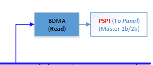
The chip sets PSPI0 as a slave, and then gets data from the sensor through PSPI, and uses a BDMA to write the obtained data into the memory at the same time;
The chip sets PSPI1 as a host, and then sends the data to the panel through PSPI, with a BDMA inside to read the data in the memory.
2. API Reference
2.1. API List
| API name | Features |
|---|---|
| MI_PSPI_CreateDevice | Create PSPI and configure PSPI properties |
| MI_PSPI_DestroyDevice | Destroy PSPI |
| MI_PSPI_Transfer | Send parameter information to PSPI, and configure the parameters of externally connected devices |
| MI_PSPI_SetDevAttr | Set PSPI properties |
| MI_PSPI_SetOutputAttr | Set PSPI output port properties |
| MI_PSPI_Enable | Enable PSPI |
| MI_PSPI_Disable | Disable PSPI |
2.2. MI_PSPI_CreateDevice
-
Features
Create PSPI and configure PSPI properties.
-
Syntax
MI_S32 MI_PSPI_CreateDevice (MI_PSPI_DEV PspiDev, MI_PSPI_Param_t *
pstPspiParam);
-
Parameter
Parameter Name Description Input/Output MI_PSPI_DEV PSPI specific devices Input MI_PSPI_Param_t Specific properties of PSPI devices Input -
Return value
-
MI_PSPI_SUCCESS Successful.
-
Not MI_PSPI_SUCCESS Failed, refer to Error code.
-
-
Requirement
-
Header: mi_pspi.h mi_pspi_datatype.h
-
Library: libmi_pspi_user.a/libmi_pspi_user.so
-
-
Note
The same PSPI device can’t be created twice in a row. If necessary, you can modify the properties of PSPI through MI_PSPI_SetDevAttr.
2.3. MI_PSPI_DestroyDevice
-
Features
Destroy PSPI.
-
Syntax
MI_S32 MI_PSPI_DestroyDevice(MI_PSPI_DEV PspiDev) ;
-
Parameter
Parameter Name Description Input/Output MI_PSPI_DEV PSPI device that needs to be destroyed. Input -
Return value
-
MI_PSPI_SUCCESS Successful.
-
Not MI_PSPI_SUCCESS Failed, refer to Error code.
-
-
Requiretment
-
Header: mi_pspi.h mi_pspi_datatype.h
-
Library: libmi_pspi_user.a/libmi_pspi_user.so
-
2.4. MI_PSPI_Transfer
-
Features
Send parameter information to PSPI, and configure the parameters of externally connected devices.
-
Syntax
MI_S32 MI_PSPI_Transfer(MI_PSPI_DEV PspiDev, MI_PSPI_Msg_t *pstMsg)
-
Parameter
Parameter Name Description Input/Output MI_PSPI_DEV PSPI specific devices Input MI_PSPI_Msg_t Specific parameters sent to the slave device Input -
Return value
-
MI_PSPI_SUCCESS Successful.
-
Not MI_PSPI_SUCCESS Failed, refer to Error code.
-
-
Requirement
-
Header: mi_pspi.h mi_pspi_datatype.h
-
Library: libmi_pspi_user.a/libmi_pspi_user.so
-
-
Note
-
The function sends data to the slave through PSPI to control the slave, For example, when using PSPI to light up the panel, you need to send some control parameters to the panel before sending specific image data, and these control parameters can be sent through this function. The number of parameters sent at one time can be controlled by the PSPI_PARAM_BUFF_SIZE macro in mi_pspi_datatype.h.
2.5. MI_PSPI_SetDevAttr
-
Features
Set PSPI properties.
-
Syntax
MI_S32 MI_PSPI_SetDevAttr(MI_PSPI_DEV PspiDev, MI_PSPI_Param_t *
pstPspiParam);
-
Parameter
Parameter Name Description Input/Output MI_PSPI_DEV PSPI specific devices Input MI_PSPI_Param_t Specific properties to be configured Input -
Return value
-
MI_PSPI_SUCCESS Successful.
-
Not MI_PSPI_SUCCESS Failed, refer to Error code.
-
-
Requirement
-
Header: mi_pspi.h mi_pspi_datatype.h
-
Library: libmi_pspi_user.a/libmi_pspi_user.so
-
-
Note
It is used to modify the properties of PSPI. Ignore it if not used.
2.6. MI_PSPI_SetOutputAttr
-
Features
Set PSPI output port properties.
-
Syntax
MI_S32 MI_PSPI_SetOutputAttr(MI_PSPI_OutputAttr_t * pstOutputAttr);
-
Parameter
Parameter Name Description Input/Output MI_PSPI_OutAttr_t Properties to be configured Input -
Return value
-
MI_PSPI_SUCCESS Successful.
-
Not MI_PSPI_SUCCESS Failed, refer to Error code.
-
-
Requirement
-
Header: mi_pspi.h mi_pspi_datatype.h
-
Library: libmi_pspi_user.a/libmi_pspi_user.so
-
-
Note
It is used to set the buffer attribute for storing sensor data. The function is useless when connecting to the panel. The default attribute of the sensor output channel is 640 * 480, YUV 422 format.
2.7. MI_PSPI_Enable
-
Features
Enable PSPI device.
-
Syntax
MI_S32 MI_PSPI_Enable(MI_PSPI_DEV PspiDev );
-
Parameter
Parameter Name Description Input/Output MI_PSPI_DEV PSPI device to be enabled Input -
Return value
-
MI_PSPI_SUCCESS Successful.
-
Not MI_PSPI_SUCCESS Failed, refer to Error code.
-
-
Requirement
-
Header: mi_pspi.h mi_pspi_datatype.h
-
Library: libmi_pspi_user.a/libmi_pspi_user.so
-
-
Note
Before using the mi_sys related interface to operate PSPI, you must call this function to enable.
2.8. MI_PSPI_Disable
-
Features
Disable PSPI.
-
Syntax
MI_S32 MI_PSPI_Disable(MI_PSPI_DEV PspiDev );
-
Parameter
Parameter Name Description Input/Output MI_PSPI_DEV PSPI device to be disabled Input -
Return value
-
MI_PSPI_SUCCESS Successful.
-
Not MI_PSPI_SUCCESS Failed, refer to Error code.
-
-
Requirement
-
Header: mi_pspi.h mi_pspi_datatype.h
-
Library: libmi_pspi_user.a/libmi_pspi_user.so
-
-
Note
When PSPI is not used, this function must be called to disenable it.
3. PSPI Data Type
3.1. PSPI data type list
The PSPI module related data types are defined as follows:
| DATA TYPE | Description |
|---|---|
| MI_PSPI_Msg_t | Define the data frame of the PSPI device parameters transmitted to the external connection. |
| MI_PSPI_OutputAttr_t | Define PSPI output port properties. |
| MI_PSPI_Param_t | Define PSPI properties. |
| MI_PSPI_DEV | Define PSPI device number. |
3.2. MI_PSPI_Msg_t
-
Description
Define the data frame of the PSPI device parameters transmitted to the external connection.
-
Definition
typedef struct{ MI_U16 u16TxSize; MI_U16 u16RxSize; MI_U8 u8TxBitCount; MI_U8 u8RxBitCount; MI_U16 au16TxBuf[PSPI_PARAM_BUFF_SIZE]; MI_U16 au16RxBuf[PSPI_PARAM_BUFF_SIZE]; } MI_PSPI_Msg_t ; -
Note
The maximum number of data transmitted each time is controlled by the macro PSPI_PARAM_BUFF_SIZE.
-
Member
Member name Description u16TxSize Number of sent data (MI_U16 type size) u16RxSize Number of received data (MI_U16 type size) u8TxBitCount The number of bits transmitted at one time when sending u8RxBitCount The number of bits transmitted at one time when receiving au16TxBuf[PSPI_PARAM_BUFF_SIZE] Send data buffer au16RxBuf[PSPI_PARAM_BUFF_SIZE] Receive data buffer -
Related data types and interfaces
PSPI_PARAM_BUFF_SIZE
MI_S32 MI_PSPI_Transfer(MI_PSPI_DEV PspiDev, MI_PSPI_Msg_t *pstMsg)
3.3. MI_PSPI_OutputAttr_t
-
Description
Define PSPI output port properties. It is used to describe the properties of the connected sensor, because PSPI has an output port only when it is connected to sensor.
-
Definition
typedef struct { MI_SYS_PixelFormat_e ePixelFormat; MI_U16 u16Width; MI_U16 u16Height; }MI_PSPI_OutputAttr_t; -
Member
Member name Description ePixelFormat Define the format of sensor input data u16Width Define the width of the sensor input image data u16Height Define the height of sensor input image data -
Related data types and interfaces
MI_S32 MI_PSPI_SetOutputAttr(MI_PSPI_OutputAttr_t * pstOutputAttr);
3.4. MI_PSPI_Param_t
- Description
Define PSPI properties.
-
Definition
typedef struct { MI_U32 u32MaxSpeedHz; MI_U16 u16DelayCycle; MI_U16 u16WaitCycle; MI_U16 u16PspiMode; MI_U8 u8DataLane; MI_U8 u8BitsPerWord; MI_U8 u8RgbSwap; MI_U8 u8TeMode; MI_U8 u8ChipSelect; }MI_PSPI_Param_t; -
Member
Member name Description Optional value u32MaxSpeedHz Max clock frequency u16DelayCycle u16WaitCycle u16PspiMode PSPI mode configuration 0:Host mode, MSB, receiving on rising edge, sending on falling edge, chip select signal active low.
SPI_CPHA: sending on rising edge, receiving on falling edge.
SPI_CPOL: sending on rising edge, receiving on falling edge SPI_CPHA|SPI_CPOL: receiving on rising edge, sending on falling edge SPI_SLAVE: PSPI as a slave SPI_LSB: PSPI LSB first SPI_SSPOL: Chip select signal polarity control, high level is effective when set.u8DataLane Number of data lines when sending DATA_SINGLE: Single line
DATA_DUAL: Double line
DATA_QUAD: Quadra lineu8BitsPerWord Number of bits sent each time Can be configured from 3 to 32 u8RgbSwap The format and the number of data lines when sending data to the panel Need to configure data_lane synchronously u8TeMode Whether to use TE mode 1: Y; 0: N u8ChipSelect PSPI chip select signal MI_PSPI_SELECT_0 MI_PSPI_SELECT_1 -
Related data types and interfaces
MI_S32 MI_PSPI_CreateDevice(MI_PSPI_DEV PspiDev, MI_PSPI_Param_t * pstPspiParam);
MI_S32 MI_PSPI_SetDevAttr(MI_PSPI_DEV PspiDev, MI_PSPI_Param_t * pstPspiParam);
3.5. MI_PSPI_DEV
-
Description
Define the PSPI number inside the chip.
-
Definition
typedef MI_S32 MI_PSPI_DEV;
-
Note
The parameter value can be set to 0 or 1, respectively representing PSPI0 and PSPI1 inside the chip. PSPI0 is used to represent receiving (RX), and PSPI1 represents sending (RX).
-
Related data types and interfaces
MI_S32 MI_PSPI_CreateDevice(MI_PSPI_DEV PspiDev, MI_PSPI_Param_t * pstPspiParam);
MI_S32 MI_PSPI_DestroyDevice(MI_PSPI_DEV PspiDev);
MI_S32 MI_PSPI_Transfer(MI_PSPI_DEV PspiDev, MI_PSPI_Msg_t * pstMsg );
MI_S32 MI_PSPI_SetDevAttr(MI_PSPI_DEV PspiDev, MI_PSPI_Param_t * pstPspiParam);
MI_S32 MI_PSPI_Disable(MI_PSPI_DEV PspiDev);
MI_S32 MI_PSPI_Enable(MI_PSPI_DEV PspiDev);
4. Program routines
4.1. Sensor routine
int main(int argc, char *argv[])
{
    int fd = 0
    MI_PSPI_DEV   pspi_dev = 0;
    MI_PSPI_Param_t  pspi_para;
    MI_PSPI_OutputAttr_t stOutputAttr;
    MI_SYS_ChnPort_t stChnPort;
    MI_SYS_BufInfo_t stBufInfo;
        MI_SYS_BUF_HANDLE hSysBuf;

    memset(&stChnPort, 0x0, sizeof(MI_SYS_ChnPort_t));
    memset(&stBufInfo, 0x0, sizeof(MI_SYS_BufInfo_t));
    memset(&hSysBuf, 0x0, sizeof(MI_SYS_BUF_HANDLE));
    memset(&pspi_para, 0x0, sizeof(MI_PSPI_SpiParam_t));

    stChnPort.eModId    = E_MI_MODULE_ID_PSPI;
    stChnPort.u32DevId  = 0;
    stChnPort.u32ChnId  = 0;
    stChnPort.u32PortId = 0;

    stOutputAttr.u16Width   = 1920;
    stOutputAttr.u16Width   = 1080;
    stOutputAttr.ePixelFormat = E_MI_SYS_PIXEL_FRAME_YUV_SEMIPLANAR_420;

    pspi_para.u8BitsPerWord    = 8;
        pspi_para.u8DataLane        = DATA_DUAL;
    pspi_para.u16DelayCycle      = 0;
    pspi_para.u16WaitCycle       = 0;
    pspi_para.u8RgbSwap         = 0;
    pspi_para.u32MaxSpeedHz     = 1000000;
    pspi_para.u16PspiMode         = SPI_SLAVE;
    pspi_para.u8ChipSelect      = MI_PSPI_SELECT_0;
/***
Send commands to the sensor via I2C etc.
***/

MI_SYS_Init();
MI_PSPI_CreateDevice(pspi_dev, &pspi_para);
MI_PSPI_SetOutputAttr(&stOutputAttr);  // Modify the properties of the sensor input image
MI_PSPI_Enable(pspi_dev);// Removed the judgment of the return value of the function call
MI_SYS_SetChnOutputPortDepth(&stChnPort,3,4);

GET_OUT_BUF:
if (MI_SUCCESS != MI_SYS_ChnOutputPortGetBuf(&stChnPort, &stBufInfo, &hSysBuf))
{
    goto GET_OUT_BUF;
}

fd = open(“picture”, O_RDWR|O_CREAT|O_TRUNC, 0777);
write(fd, tBufInfo.stFrameData.pVirAddr[0], stBufInfo.stFrameData.u32BufSize));
sync();
close(fd);

PUT_OUT_BUF:
if (MI_SUCCESS != MI_SYS_ChnOutputPortPutBuf(hSysBuf))
{
    goto PUT_OUT_BUF;
}

MI_SYS_SetChnOutputPortDepth(&stChnPort,0,3);
MI_PSPI_Disable(pspi_dev);
MI_PSPI_DestroyDevice(pspi_dev);
MI_SYS_Exit();
Return 0;
}
4.2. Panel routine
int main(int argc, char *argv[])
{
    MI_S32 s32Ret = 0;
    MI_U16 * buff = NULL;
    MI_U32 size = 0;
    MI_PSPI_Msg_t  pspi_msg;
    MI_PSPI_Param_t  pspi_para;
    MI_PSPI_DEV   pspi_dev = 1;
    MI_SYS_ChnPort_t  stChnPort;
    MI_SYS_BUF_HANDLE  stHandle;
    MI_SYS_BufInfo_t   stBufInfo;
MI_SYS_BufConf_t  stBufConf;

    pspi_para.u8BitsPerWord    = 9;
        pspi_para.u8DataLane       = DATA_SINGLE;
    pspi_para.u16DelayCycle    = 2;
    pspi_para.u16WaitCycle     = 2;
    pspi_para.u8RgbSwap        = 0;
    pspi_para.u32MaxSpeedHz    = 1000000;
    pspi_para.u16PspiMode      = 0;
    pspi_para.u8ChipSelect     = MI_PSPI_SELECT_0;
    pspi_para.u8TeMode         = 0;
    MI_PSPI_CreateDevice(pspi_dev, &pspi_para);// Removed the judgment of the return value of the function call
    memset(&pspi_msg, 0 ,sizeof(MI_PSPI_Msg_t));
    pspi_msg.u8TxBitCount = 9;// Different values can be selected according to different panels
    pspi_msg.u8RxBitCount = 8;
    pspi_msg.u8TxSize = 1;
    //0xDA   // Send the corresponding control command according to the panel model, depending on the panel model
    pspi_msg.au16TxBuf[0] = 0xDA;
    MI_PSPI_Transfer(pspi_dev,  & pspi_msg);
    /****    Send command to panel   *****/
    memset(&stChnPort, 0, sizeof(MI_SYS_ChnPort_t));
    memset(&stBufConf, 0, sizeof(MI_SYS_BufConf_t));
    memset(&stBufInfo, 0, sizeof(MI_SYS_BufInfo_t));
    memset(&stHandle, 0, sizeof(MI_SYS_BUF_HANDLE));

    stChnPort.eModId = E_MI_MODULE_ID_PSPI;
    stChnPort.u32DevId = 1;
    stChnPort.u32ChnId = 0;
    stChnPort.u32PortId = 0;

    stBufConf.eBufType = E_MI_SYS_BUFDATA_FRAME;
    stBufConf.stFrameCfg.u16Height = 240;
    stBufConf.stFrameCfg.u16Width  = 320;// Depends on the situation
    stBufConf.stFrameCfg.eFrameScanMode = E_MI_SYS_FRAME_SCAN_MODE_PROGRESSIVE;
    stBufConf.stFrameCfg.eFormat    = E_MI_SYS_PIXEL_FRAME_RGB565;

    MI_PSPI_Enable(pspi_dev);
while(1)
{
getBuff1:
if(MI_SYS_ChnInputPortGetBuf(&stChnPort,&stBufConf,&stBufInfo,&stHandle,4000)!= MI_SUCCESS)
            {
                printf("get input port buf red failed\n");
                goto getBuff1;
            }
            else
            {
                printf("MI_SYS_ChnInputPortGetBuf success 1\n");

                buff =  (MI_U16 *)stBufInfo.stFrameData.pVirAddr[0];
                size = stBufInfo.stFrameData.u32BufSize/2;
                for(i = 0; i < size ; i++)
                {
                    buff[i] = 0xf800;
                }

            putbuff1:
                if(MI_SYS_ChnInputPortPutBuf(stHandle, &stBufInfo, FALSE) != MI_SUCCESS)
                {
printf("writter frame err 1\n");
                    goto putbuff1;
                }
                else
                    printf("written a frame red to screen success\n");
            }
        }
4.3. Panel display Sensor image routine
(Because the pixel and format of the sensor image currently in use are different from the panel, a vpe module must be connected in between them. For the related configuration of the vpe module, please refer to MI_VPE_API.)
#define           FRAME_RATE                 30
int main(int argc, char *argv[])
{
    MI_S32 s32Ret = 0;
    MI_SYS_ChnPort_t stSensorChnPort;
    MI_SYS_ChnPort_t stPanelChnPort;
    MI_SYS_ChnPort_t stDivpChnPort;

    MI_SYS_BindType_e eBindType;
    MI_U32 u32BindParam;
MI_SYS_Init();
/* Initialize and enable sensor, refer to section 4.1 */
/* Initialize and enable panel, refer to section 4.2 */

//vpe initialization
MI_DIVP_ChnAttr_t stAttr;
MI_DIVP_OutputPortAttr_t stOutputPortAttr;
memset(&stAttr, 0, sizeof(stAttr));

stAttr.bHorMirror = false;
stAttr.bVerMirror = false;
stAttr.eDiType = E_MI_DIVP_DI_TYPE_OFF;
stAttr.eRotateType = E_MI_SYS_ROTATE_NONE;
stAttr.eTnrLevel = E_MI_DIVP_TNR_LEVEL_OFF;
stAttr.stCropRect.u16X = 0;
stAttr.stCropRect.u16Y = 0;
stAttr.stCropRect.u16Width = 640;
stAttr.stCropRect.u16Height = 480;
stAttr.u32MaxWidth = 640;
stAttr.u32MaxHeight = 480;

s32Ret = MI_DIVP_CreateChn(0, &stAttr);
stOutputPortAttr.eCompMode = E_MI_SYS_COMPRESS_MODE_NONE;
stOutputPortAttr.ePixelFormat = E_MI_SYS_PIXEL_FRAME_RGB565;
stOutputPortAttr.u32Width = 240;
stOutputPortAttr.u32Height = 320;
s32Ret = MI_DIVP_SetOutputPortAttr(0, &stOutputPortAttr);
s32Ret = MI_DIVP_StartChn(0);

stSensorChnPort.eModId = E_MI_MODULE_ID_PSPI;
stSensorChnPort.u32DevId = 0;
stSensorChnPort.u32ChnId = 0;
stSensorChnPort.u32PortId = 0;

stDivpInputChnPort.eModId = E_MI_MODULE_ID_DIVP;
stDivpInputChnPort.u32DevId = 0;
stDivpInputChnPort.u32ChnId = 0;
stDivpInputChnPort.u32PortId = 0;
    stPanelChnPort.eModId = E_MI_MODULE_ID_PSPI;
    stPanelChnPort.u32DevId = 1;
    stPanelChnPort.u32ChnId = 0;
    stPanelChnPort.u32PortId = 0;

    eBindType = E_MI_SYS_BIND_TYPE_FRAME_BASE;
    u32BindParam = 0;

    MI_SYS_SetChnOutputPortDepth(&stSensorChnPort,3,6);

    MI_SYS_BindChnPort2(&stSensorChnPort, &stDivpChnPort, FRAME_RATE, FRAME_RATE, eBindType, u32BindParam);

    MI_SYS_BindChnPort2(&stDivpChnPort, &stPanelChnPort, FRAME_RATE, FRAME_RATE, eBindType, u32BindParam);

    While(1)
    {
        sleep(10);
    }

    MI_PSPI_Disable(0);
    MI_PSPI_Disable(1);
    MI_PSPI_DestroyDevice(0);
    MI_PSPI_DestroyDevice(1);

    return 0;
}
5. Error code
PSPI API error codes are shown as follow:
| Error code | Definition | Description |
|---|---|---|
| 0 | MI_PSPI_SUCCESS | Function runs successfully |
| -1 | MI_PSPI_FAIL | Function runs failed |
| -2 | MI_ERR_PSPI_NULL_PTR | Input null pointers |
| -3 | MI_ERR_PSPI_NO_MEM | No memory |
| -4 | MI_ERR_PSPI_ILLEGAL_PARAM | Enter illegal and inappropriate parameters |
| -5 | MI_ERR_PSPI_DEV_NOT_INIT | PSPI doesn`t initialized |
| -6 | MI_ERR_PSPI_ENABLE_CHN_FAILED | Enable channel failed |
| -7 | MI_ERR_PSPI_ENABLE_PORT_FAILED | Enable port failed |
| -8 | MI_ERR_PSPI_DISABLE_CHN_FAILED | Disenable channel failed |
| -9 | MI_ERR_PSPI_DISABLE_PORT_FAILED | Disenable port failed |
| -10 | MI_ERR_PSPI_DEV_HAVE_INITED | PSPI initialized |
| -11 | MI_ERR_PSPI_FAILED_IN_MHAL | Run error in MHAL |