SSD_PWM REFERENCE
1. Overview
Demo board support 4 channels PWM output.
2. Dts Config
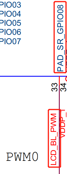
2.1. Demo board supported PWM Padmux
Provide 4 groups of PWM, each group has 3 choices.
Note: For each group, only one of them can be selected.
Table 2-1
| PWM Group | Mode | PAD |
|---|---|---|
| PWM0 | 7 | PAD_KEY0 |
| 8 | PAD_KEY10 | |
| 10 | PAD_GPIO1 | |
| PWM1 | 7 | PAD_KEY1 |
| 8 | PAD_KEY11 | |
| 10 | PAD_GPIO2 | |
| PWM2 | 7 | PAD_KEY2 |
| 8 | PAD_KEY12 | |
| 10 | PAD_GPIO3 | |
| PWM3 | 7 | PAD_KEY3 |
| 8 | PAD_KEY13 | |
| 10 | PAD_GPIO4 |
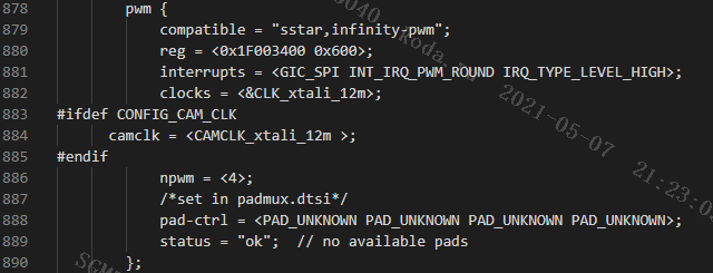
2.2. Configure PWM Node Attributes
-
npwm: 4: 4 sets of pwm, configure according to 4, no need to modify.
-
The pad-ctrl sets the pads of each PWM output in sequence.
pad-ctrl = <PWM0_PAD PWM1_PAD PWM2_PAD PWM3_PAD>;
If you don't want to output PWM signal, you can set the corresponding position as PAD_UNKNOWN.
pioneer3.dtsi:
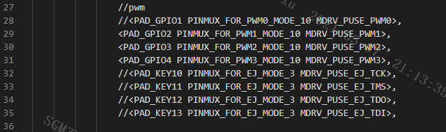
2.3. Padmux Config
Comment out the PADs that are not configured as PWM output.
pioneer3-ssc020a-s01a-demo-camera-padmux.dtsi
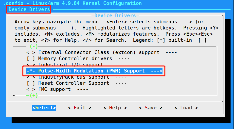
3. Kernel config
-
Open the support for PWM in Kernel.
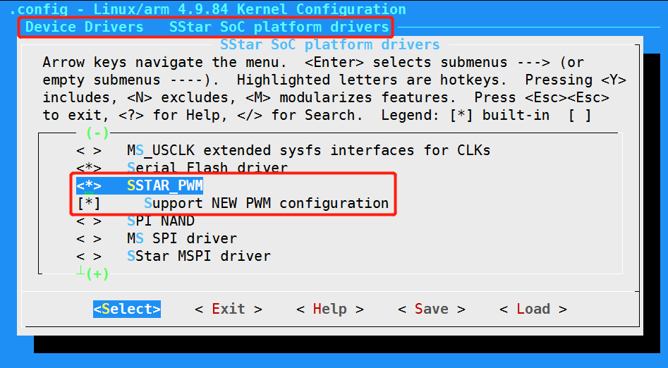
-
Open the PWM driver config in SStar
4. Parameters Of PWM
4.1. Parameter Config
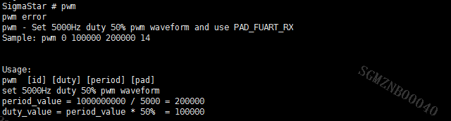
The currently supported PWM clk output is 12MHz.
Ex: Set 5000Hz duty 25% pwm waveform
period_value = 1000000000 / 5000 = 200000

duty_value = period_value * 25%  = 50000
4.2. Duty_cycle
Echo 50000> duty_cycle: The duty cycle is 25%.
4.3. Period
Frequency。
Echo 200000> period: 5kHz pwm.
4.4. Enable/disable
Enable:
echo 1 > enable
4.5. Polarity
If it is normal, duty_cycle=25%, and the high level is 25%.
If it is inverse, it is the opposite of the above.
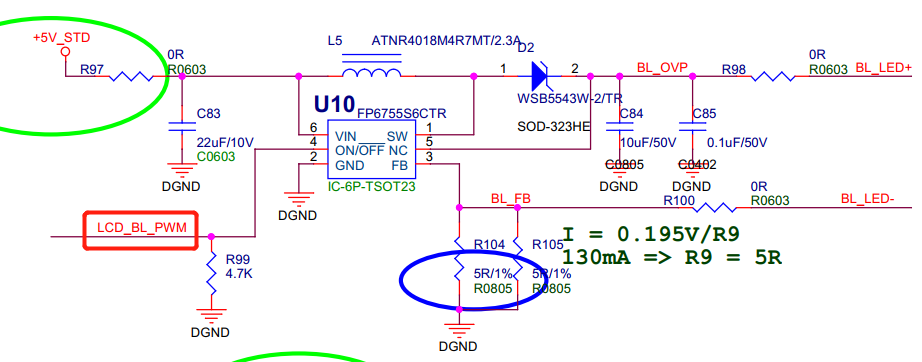
5. Hardware Examples
6. PWM Test
6.1. Check PWM Settings
Read reg in Uboot to check the PWM settings.
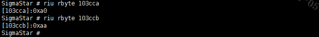
Bit0~bit3 of 103cca correspond to PWM0, which is not set; bit4~bit7 of 103cca correspond to PWM1, set mode10; bit0~bit3 of 103ccb correspond to PWM2, set mode10; bit4~bit7 of 103ccb correspond to PWM3, set mode10. If it is consistent with the actual setting, it is normal.
Read reg in Kernel to check the PWM settings.

The address read in Kernel is 16bit, shift 0xca one bit to the right, and read the data at address 65. The data is 0xAAA0, which means that PWM0 is not set. PWM1, PWM2, and PWM3 are all set to mode10, which are consistent with the actual setting.
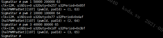
6.2. Set PWM in Uboot
Use the pwm tool to set up, commands are as follows.
Set PWM1, PWM2, PWM3 to correspond to gpio63, gpio64, and gpio65 respectively.
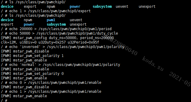
6.3. Set PWM in Kernel
Set the period, duty cycle, polarity, and enable status of PWM1.
7. Demo
7.1. Kernel Demo
Test code: test_pwm.c
Take the PWM1 test as an example:
-
Compile the code to generate a test bin.
arm-linux-gnueabihf-gcc –o test_pwm test_pwm.c
-
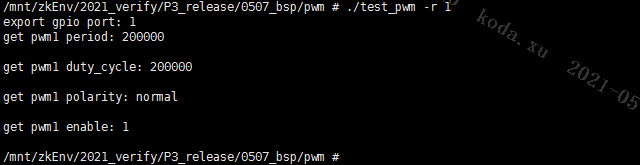
Mount to the board and execute the test bin file.
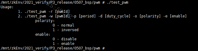
Read the default settings of PWM1:
Modify the attributes of PWM1:
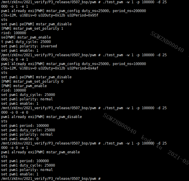
Set polarities:
inversed, the duty cycle is 75%, enable;
normal, the duty cycle is 25%, enable;
normal, the duty cycle is 25%, disabled;
normal, the duty cycle is 25%, enable;
You can see the changes in the panel backlight: brighter -> darker -> black -> darker.
The test demo settings take effect.