SSD_Touch Screen Driver Reference
1. Driver Configuration
1.1. Overview
The touch IC drivers currently implemented by the SSD platform are all communicated through I2C. Take the driver example of the public version of Goodix here. Please refer to the driver's suggestion for the actual situation .
1.2. Driver Integration
Please ask touch IC manufacturer to provide linux version touch screen driver. The touch driver belongs to the input subsystem. After the driver is loaded successfully, the device node /dev/input/eventX will be generated (generally, if no other input subsystem exists, event0 will be generated)
-
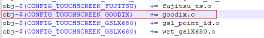
Add the linux driver provided by the IC manufacturer to the kernel/drivers/input/touchscreen/ directory, as shown below, add the driver file link in kernel/drivers/input/touchscreen/Makefile, and use a configuration CONFIG_TOUCHSCREEN_GOODIX to control
-
As shown below, add CONFIG_TOUCHSCREEN_GOODIX in kernel/drivers/input/touchscreen/Kconfig to add make menuconfig configuration switch in kernel config

-
In the project use stage, open the corresponding config through the make menuconfig configuration to ensure that Build in to the kernel
2. DTS configuration
2.1. DTS configuration
View the hardware schematic diagram, refer to the driver source code, find the *.dtsi file used by the project, and add the corresponding device tree node to configure it for the driver. The configuration process is as follows:
-
Configure the compatible name of the device tree node according to the name used by the driver
-
i2c slave addr for touch IC
-
The RST/Interrupts pin connecting the touch IC to the main chip
2.2. DTS configuration example
The configuration example of the SSD20X platform is used here. Except that the corresponding *.dts files need to be configured according to the files used, the configuration process is general.
Example use: kernel/arch/arm/boot/dts/infinity2m-ssc011a-s01a-display.dtsi (please add it to the dtsi used by the project during actual use)
-
View the driver source code, find .of_match_table, and create a device node named with this name in dtsi
View the driver source code:
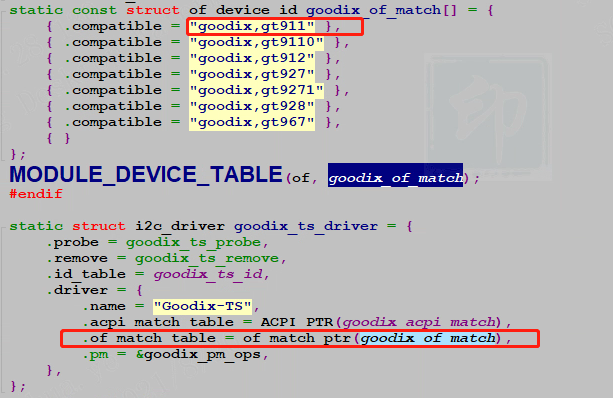
Configured device node
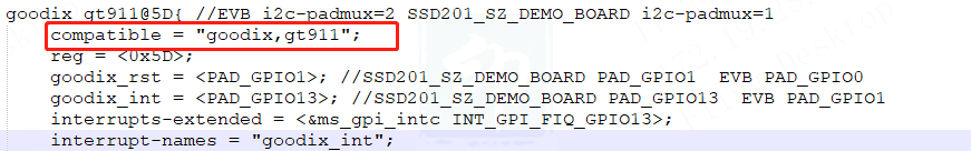
-
According to the I2C slave addr provided by the touch IC manufacturer, configure the reg attribute. Here, the I2C slave addr address of goodix is 0x5D (requires confirmation from the IC manufacturer)
-
According to the hardware connection of the device tree node, configure the pins corresponding to the two attributes of goodix_rst/goodix_int (the attribute name needs to match the driver PAD_GPIO1/PAD_GPIO13 (it needs to match the actual hardware), and the reg configuration is the touch I2C
Note : It is best not to repeat the touch devices. If other touch devices are added to the project, please turn off the Goodix driver of the public version Default in the config.
3. STR configuration
STR: Suspend To Ram
If you need to support STR, you need to confirm with the FAE of the touch IC that the suspend/resume interface has been implemented in the touch driver, otherwise the touch may fail to resume after STR.

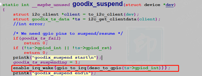
If the touch wake-up STR function is required, the driver code needs to enable the touch-corresponding interrupt as a wake source before suspend:
4. Common FAQ
-
Is the driver loaded successfully?
$ \rightarrow $ Confirm the device node generated by the corresponding touch device (eg:/dev/input/eventX)
-
There is no response to the touch , how can I confirm whether the communication is successful?
$ \rightarrow $ Check the log to see if there is any corresponding I2C group communication error, if there is an error, it may fail to communicate with the touch IC
$ \rightarrow $ The oscilloscope captures the I2C waveform to see if there is data interaction
-
How to check the touch version information?
$ \rightarrow $ Demo with attachment: ./Evtest /dev/input/eventX 2
-
What is the reason for the inaccurate touch?
$ \rightarrow $ Make sure the UI draw size matches the touch resolution
$ \rightarrow $ Use the attached Demo to check whether the reported coordinates are accurate: ./Evtest /dev/input/eventX 0
$ \rightarrow $ Use the attachment to provide Demo simulation input coordinates to trigger the corresponding click: ./Evtest /dev/input/eventX 1 X_position Y_position
5. Demo
-
Demo_Bin
-
Src_Code
Compile method: gcc evtest.c -o Evtest
-
Instructions for use
1. Read coordinates:
./evtest /dev/input/event0 0 //The test event0 selected by the device node is followed by a 0 to read cmd
2. Write coordinates:
./evtest /dev/input/event0 1 90 90 //The test event0 selected by the device node is followed by a 1 to write cmd, and write cmd with x, y coordinates
3. dump dev info:
./evtest /dev/input/event0 2 //The test event0 selected by the device node, the next 2 is Dump Dev related information