SDK Architecture Introduction
1. Keywords
| Abbr | Full name | Introduction |
|---|---|---|
| SYS | System |
Realize MI system initialization, memory buffer pool management, and data flow management between various modules |
| VDEC | Video Decoder | H264/H265/JPEG video decoder |
| DIVP | Deinterlace&Video Post Process Engine | DIVP Engine has two main functions: 1.Converting the format of the decoded data 2.Scaling the decoded data |
| VDISP | Vitrual Display | Software puzzle |
| DISP | Display Engine | DISP does a hardware puzzle for the image output by the VDEC/DIVP processing unit, and encodes it together with the AO output audio signal into an HDMI/VGA/CVBS output signal unit |
| VENC | Video Encoder | H264/H265/MotionJpeg video decoder |
| AI | Audio Input Interface | I2S audio input acquisition unit |
| AO | Audio Output Interface | Audio output |
| GFX | Graphics Engine | Graphic Engine provides basic hardware acceleration support for 2D drawing, reducing CPU load |
| FB | FrameBuffer | UI display |
| HDMI | High Definition Multimedia Interface | HDMI/VGA standard output |
2. Software Architecture

-
The function realization function is divided into MI API layer, MI implement layer, Hal hardware abstraction layer, Driver layer and chip hardware layer from top to bottom.
-
The SDK function code is implemented in the Kernel mode, which reduces the scheduling from kernel to User mode and improves the efficiency of logic function implementation.
-
For the User Mode interface of the MI API provided by the upper-level client, the user-level APP directly calls the MI interface to call the corresponding MI function.
3. SDK directory structure
| catalog | module | function |
|---|---|---|
| project | board | PCB board information storage path |
| project | configs | Pre-configuration file storage path |
| project | image | The storage path of image file and library that generate image file |
| project | kbuild | Kernel compilation environmentkernel |
| project | release | Target pool, storing external header files, library files, kernel modules and third-party libraries |
| SDK | Verify/feature | Verification folder, which stores module unit test and feature test files |
| SDK | Verify/demo | Overall function test demo |
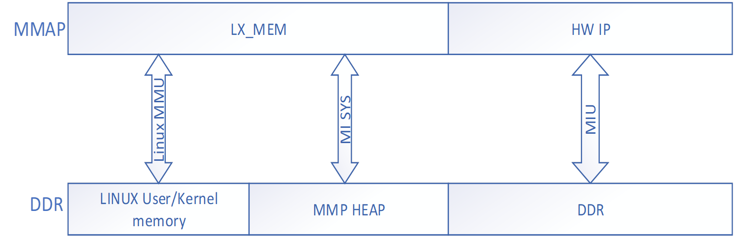
4. Memory management
Please refer to Memory Layout for details.
-
Memory reserved through mmap.ini
-
Support mma to manage module memory, each module is allocated from the size reserved by mma
5. Basic Concepts
-
Data Stream
Each mi module can be regarded as a data processing unit, and the data flow is uniformly scheduled by MI SYS. The input data stream represents the data received by the unit, and the output data stream represents the data processed by the unit.
-
Control Stream
APP controls the parameters of each mi module data processing process, such as setting MI_VENC encoding parameters, starting and stopping MI_VPE channel, setting MI_VPE channel output port resolution and format, etc.
-
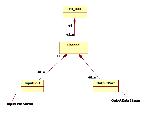
Channel
-
For an mi module that needs to process or output a stream, a channel represents the time-multiplexed context and related control flow settings that it processes or outputs a stream.
-
The time-multiplexed module can support multiple channels, such as MI_VDEC, MI_DIVP, MI_DISP.
-
-
Port
-
Port is divided into two types, input port and output port. The input port is the location of the channel's input data stream, and the output port is the location of the channel's output data stream.
-
A channel can have multiple input ports and output ports.
-
6. API
Please refer to SDK Module API for details.
7. DEBUG method
Please refer to the corresponding chapter PROCFS INTRODUCTION of each module API in SDK Module API for details.