SSD_SPI REFERENCE
1. Overview
This article mainly introduces how to use SPI interface in Linux Uboot and Linux User Space.
Table 1-1 Specification
| Peripherals | Highest clock |
|---|---|
| 2 SPI | 72MHz |
Under the SSD22X platform, mspi only supports LSB reading and does not support LSB writing.
2. SPI Control
2.1. Use SPI in Uboot
2.1.1. SPI Driver Analysis
SPI Driver file path in Uboot: boot/drivers/mstar/spi/pioneer3/mspi.c
Table 2-1: API function
| API name | Function |
|---|---|
| MDrv_MSPI_Init | Initialize SPI, configure PADMUX |
| MDrv_MSPI_DCConfig | Configure SPI Timing; use the default config |
| MDrv_MSPI_SetMode | Set SPI working mode |
| MDrv_MSPI_FRAMEConfig | Configure the data format of SPI transmission |
| MDrv_MSPI_SetCLK | Set SPI working clock |
| MDrv_MSPI_ChipSelect | SPI Chip Select |
| MDrv_MSPI_Write | SPI write data |
| MDrv_MSPI_Read | SPI read data |
| MDrv_MSPI_DMA_Write | SPI enables DMA to write data |
| MDrv_MSPI_DMA_Read | SPI enable DMA to read data |
| HAL_MSPI_FullDuplex | SPI full-duplex communication, read while writing |
| HAL_MSPI_Set3WireMode | Configure SPI to 3Line mode |
| HAL_MSPI_SetLSB | When configuring SPI transmission, the low bit has priority, but default high |
2.1.2. SPI PADMUX Config

The padmux table is provided in the code of the SPI Driver source file, which lists the supported SPI PADMUX modes. Users can find the corresponding pins in CheckList (it is suggest to use the recommended mode).
The default config is PINMUX_FOR_SPI0_MODE_4 when using MSPI0, PADMUX can be changed by modifying the value of MSPI0_PADMUX_MODE; The default config is PINMUX_FOR_SPI1_MODE_5 when using MSPI1, PADMUX can be changed by modifying the value of MSPI1_PADMUX_MODE.
2.1.3. SPI Function Test
Uboot provides source files and related commands for testing SPI communication.
Path: boot/common/cmd_spi.c
Users can refer to the do_spi function to write code.
Enable the following options in menuconfig to enable SPI Driver and test commands.
Command line interface

-> Device access commands
        -> [*] sspi

Device Drivers

-> [*] MStar drivers
    -> [*] SSTAR MSPI
Connect SDI and SDO on SPI, if the sent and recived data are the same, the SPI communication is normal.
Run # sspi 1:0.0 1 55 in Uboot to test SPI communication.
Command format: sspi [mspi0/mspi1]:[cs].[mode] [size] [data], The default transmission data is 8bits.
2.2. Use SPI in UserSpace
The following modes and pins are recommanded, please refer to checklist for modifying as you need.
| Spi Group | Mode | SPI_CZ | SPI_CK | SPI_DI(MOSI) | SPI_DO(MISO) | DEV |
|---|---|---|---|---|---|---|
| SPI 0 | 4 | PAD_KEY10 | PAD_KEY11 | PAD_KEY12 | PAD_KEY13 | /dev/spidev0.0 |
| SPI 1 | 5 | PAD_KEY0 | PAD_KEY1 | PAD_KEY2 | PAD_KEY3 | /dev/spidev1.0 |
The followings are take SPI1_MODE_5 as an example to introduce, and the pins are from PAD_KEY0 to PAD_KEY3.
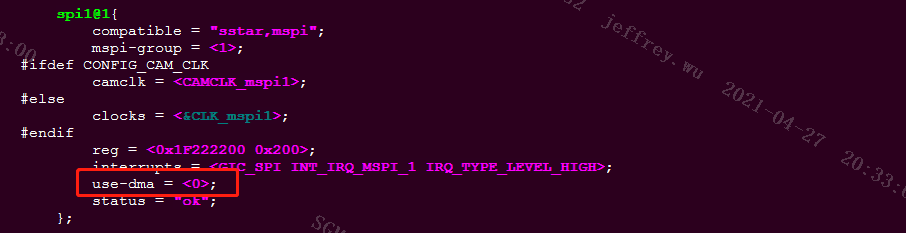
2.2.1. Configure DTS in Kernel
Configure spi1 in kernel/arch/arm/boot/dts/pioneer3.dtsi, the DMA function marked in the following figure can be set as you need.
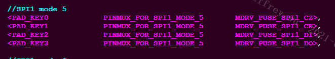
2.2.2. Configure PADMUX in Kernel
Congiure the spi padmux in kernel/arch/arm/boot/dts/ pioneer3-ssc020a-s01a-demo-padmux.dtsi. If they are reused for other functions, the remaining groups need to be annotated.
Configure the pin as PINMUX_FOR_SPI1_MODE_5 as follows.
2.2.3. Enable SPI Function in Kernel
Configure the following options in menuconfig to enable SPI function.
Device Drivers

->  [*] SPI support
    ->  <*> User mode SPI device driver support
->  [*] SStar SoC platform drivers
    ->  <*> SStar MSPI driver
If it succeeds, there will be spidev0.0 and spidev1.0 in /dev of the demo board after the kernel runs.
2.2.4. Test SPI Communication in UserSpace
Sample code for testing: mspi_main.c
Use # arm-linux-gnueabihf-gcc -o mspi_main mspi_main.c to build the source file, generate an executable bin file and test the SPI communication. Copy mspi_main to demo board, and run # ./mspi_main 8 55 in shell.
Command format: ./mspi_main [bits] [data]
Set the data format [bits] of SPI transmission, convert the obtained string into [data], send it by SPI_DI (MOSI), and receive the data input by SPI_DO (MISO). Connect SPI_DI (MOSI) with SPI_DO (MISO). If the sent and received data are the same, the SPI communication is normal.
2.2.5. Check the SPI Config
When SPI communication is abnormal:
-
Check whether the HW connection is correct;
-
Check whether the SPI register config is correct;
The padmux table in the kernel driver file lists the register base address, offset address, and valid bits. Open
kernel/drivers/sstar/gpio/pioneer3/mhal_pinmux.cto find the SPI pin.The following figure shows the register info when SPI is configured as PINMUX_FOR_SPI1_MODE_5.
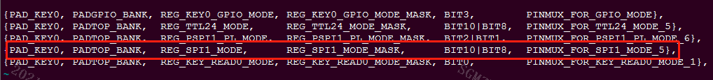
Base address PADTOP_BANK 0x103C Offset address REG_SPI1_MODE 0x68 Valid bits BIT10|BIT8 0x0500 Run
/customer/riu_r 0x103C 0x68in demo board to read the value of register. The SPI PADMUX register configuration is correct what if the value is 0x0500.Note: The priority of GPIO MODE is higher than SPI MODE. Only when the pin of this group is not GPIO MODE can it be configured as SPI MODE.
3. Use GPIO to Simulate SPI
3.1. Determine the GPIO Pin
SPI is the standard communication protocol, controlling GPIO level can simulate SPI reading and writing timing to realize data reading and writing.
-
Find four pins as CLK, CS, MOSI, MISO respectively.
-
Determine GPIO ID when use GPIO in userspace.
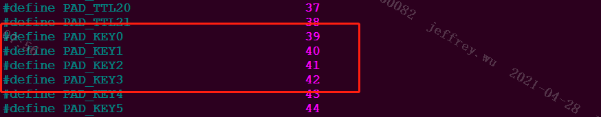
The header file provided in the kernel lists the ID corresponding to each pin.
kernel/drivers/sstar/include/pioneer3/gpio.h
Take PAD_KEY0 ~ PAD_KEY3 as examples, the corresponding GPIO ID is shown as follows.
3.2. Test Simulation Effect
Sample code for testing: mspi_gpio.c.
Use # arm-linux-gnueabihf-gcc -o mspi_gpio mspi_gpio.c to build the source file, generate an executable bin file and test the SPI communication. Copy mspi_gpio to demo board, and run # ./mspi_gpio 8 55 in shell.
Command format: ./mspi_gpio [bits] [data]
Set the data format [bits] of SPI transmission, convert the obtained string into [data], send it by MOSI, and receive the data input by MISO. Connect MOSI with MISO. If the sent and received data are the same, the SPI communication function simulated by GPIO is normal.
Note: Sample code mainly introduces the software implementation method of GPIO simulate SPI. Using this method, the read and write clock rate is about 4K. If you want to increase the clock frequency, you need to read and write GPIO faster. For details, see GPIO Reference.