SSD_PANEL CLICKING REFERENCE
1. CONFIRM WHETHER SPEC IS SUPPORTED
Before clicking the panel, confirm whether the clk of the panel is supported. The spec of TTL output CLK is as follows:
| Min (MHz) | Max (MHz) | |
|---|---|---|
| SSD20X | 9 | 75 |
| SSD21X & SSD22X | 6 | 75 |
| SSC268 | 2.3 | 74.25 |
Calculation method: htotal * vtotal * fps
The spec of MIPI DSI output CLK is as follows:
| Min (bps/lane) | Max (bps/lane) | |
|---|---|---|
| SSD20X | 100M | 1.5G |
| SSD21X & SSD22X | - | - |
| SSC268 | 100M | 1.5G |
Calculation method: H_Total * V_Total * FPS * BitsPerPixel / lane number
BitsPerPixel=24(RGB888)/18(RGB666)/16(RGB565)
2. CONFIGURE PANEL-RELATED PIN
First, confirm the pin used according to the hardware schematic diagram, and then switch to the corresponding mode in the dts of the kernel.
2.1. TTL
Check the hardware schematic diagram and confirm the pin used by the TTL Panel.

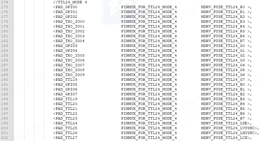
Check the tmux table in HW CheckList to confirm the mode corresponding to TTL and the pin setting in padmux, as shown in the figure below, using ttl24 mode4, the pin is PAD_GPIO0~PAD_GPIO7, PAD_TX0_IO00~PAD_TX0_IO09 , PAD_TTL18~PAD_TTL27:

Configure as PINMUX_FOR_TTL24_MODE_4 in padmux:
2.2. MIPI
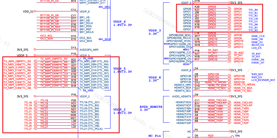
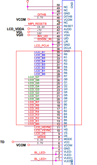
Check the hardware schematic diagram and confirm the pins used by MIPI panel are TTL_R3~TTL_R7, TTL_G2~TTLG6.
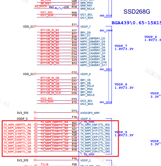
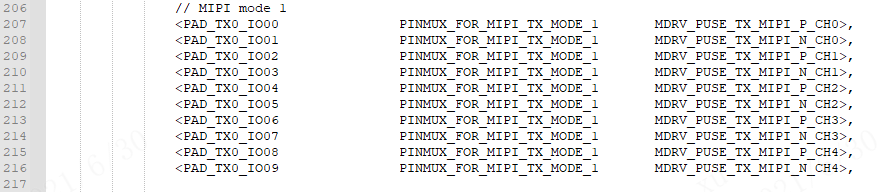
Check the tmux table in HW CheckList to confirm the mode corresponding to MIPI and the pin setting in padmux. As shown in the figure below, using mipi mode1, the pin is PAD_TX0_IO00~PAD_TX0_IO09:

Configure as PINMUX_FOR_TX_MIPI_MODE_1 mode in padmux:
3. PANEL PARAMETER SETTINGS
3.1. TTL Panel Parameter Setting
First find an already configured TTL screen parameter with the same resolution, and then fill in the following parameters according to the panel spec:
u16HSyncWidth & u16HSyncBackPorch & u16VSyncWidth & u16VSyncBackPorch
The corresponding panel spec data is as follows:
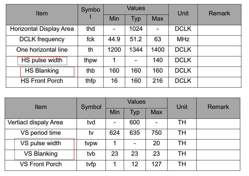
u16HStart=u16HSyncWidth + u16HSyncBackPorch

u16VStart=u16VSyncWidth + u16VSyncBackPorch
The panel spec data corresponding to u16Width & u16Height are as follows:
u16HTotal=u16Width+u16HSyncWidth+u16HSyncBackPorch+HSyncFrontPorch

u16VTotal=u16Height+u16VSyncWidth+u16VSyncBackPorch+VSyncFrontPorch
The corresponding panel spec data is as follows:

u16DCLK = u16HTotal * u16VTotal * frequence(60)/1000*1000
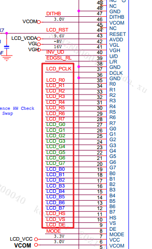
The following three parameters correspond to the data of the three channels of R/G/B whether to swap:
u8SwapOdd_RG & u8SwapEven_RG & u8SwapOdd_GB
The corresponding channel selection is as follows:
0 default (Do not swap)

1 select R

2 select G

3 select B
u8SwapEven_GB indicates whether the high and low bits of the rgb data line swap.
As shown in the figure below, R and B and the high and low positions are reversed, so the config of the panel parameters is 3,2,1,1:
3.2. MIPI Panel Parameter Setting
The main difference between mipi panel and ttl panel screen parameter settings is that it requires additional configuration of mipi data line related data.
The following corresponds to whether mipi's four pairs of data line & clk line need swap, which can be set according to the line sequence and screen parameter configuration of the public version.
The members of this structure MI_PANEL_ChannelSwapType_e represent panel:
eCh0, eCh1, eCh2, eCh3, eCh4 correspond to panel CLK CH, Data CH0, Data CH1, Data CH2, Data CH3 in turn.
The value selected by eCh is as follows:
0 - use soc TX_MIPI_D0

1 - use soc TX_MIPI_D1

2 - use soc TX_MIPI_CK

3 - use soc TX_MIPI_D2

4 - use soc TX_MIPI_D3
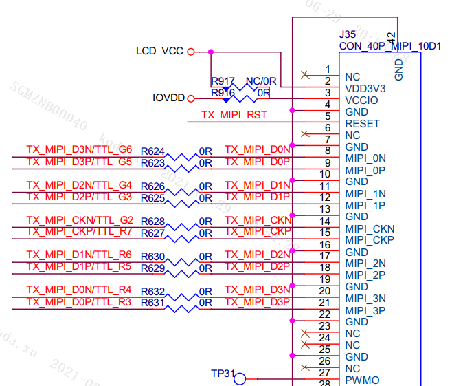
Refer to the schematic diagram: (soc pin on the left, panel pin on the right)
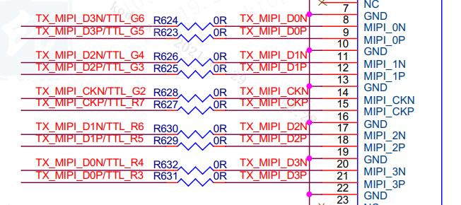
Connection of panel and soc:
CLK CH    <-> panel TX_MIPI_CK  <->   soc TX_MIPI_CK     2

Data CH0 <-> panel TX_MIPI_D0  <->   soc TX_MIPI_D3    4

Data CH1 <-> panel TX_MIPI_D1  <->   soc TX_MIPI_D2    3

Data CH2 <-> panel TX_MIPI_D2  <->   soc TX_MIPI_D1    1

Data CH3 <-> panel TX_MIPI_D3 <->   soc TX_MIPI_D0     0
The config should be:
(MI_PANEL_ChannelSwapType_e)2,               - CLK CH
(MI_PANEL_ChannelSwapType_e)4,               - Data CH0
(MI_PANEL_ChannelSwapType_e)3,               - Data CH1
(MI_PANEL_ChannelSwapType_e)1,               - Data CH2
(MI_PANEL_ChannelSwapType_e)0,               - Data CH3
The panel parameters are set to:
m_ucClkLane      = 2        (CLK CH)

m_ucDataLane0 = 4        (Data CH0)

m_ucDataLane1 = 3        (Data CH1)

m_ucDataLane2 = 1        (Data CH2)

m_ucDataLane3 = 0        (Data CH3)
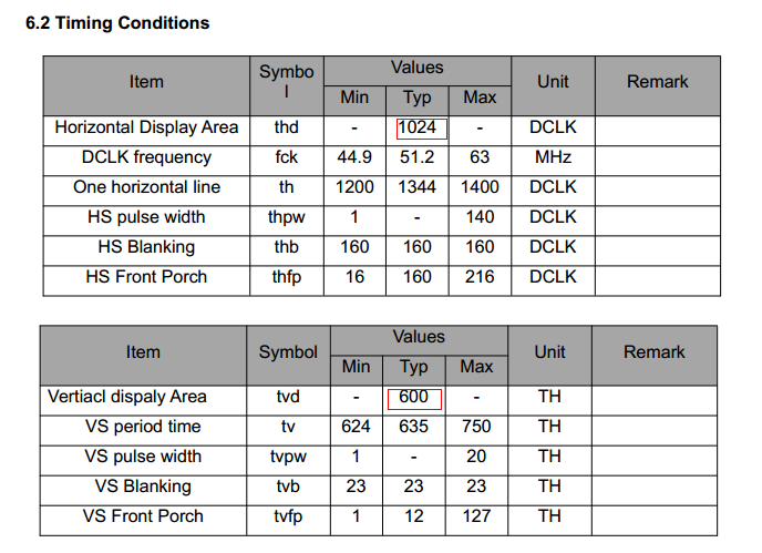
The parameters that MIPI Panel needs to focus on are as follows:
m_wHactive, m_wHpw, m_wHbp, m_wHfp

m_wVactive, m_wVpw, m_wVbp, m_wVfp
These parameters correspond to those in the panel spec:
u16Width, u16HSyncWidth, u16HSyncBackPorch, HSyncFrontPorch

u16Height, u16VSyncWidth, u16VSyncBackPorch, VSyncFrontPorch
m_wFps is set to 60 by default.
enLaneNum corresponds to mipi line mode and is configured according to the actual situation.
m_pCmdBuf corresponds to the initial cmd of mipi, provided by the panel factory.
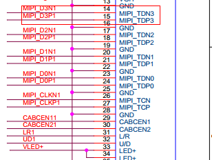
m_ucPolCh0, m_ucPolCh1, m_ucPolCh2, m_ucPolCh3, m_ucPolCh4 correspond to the four sets of mipi data. Whether a group of clk lines need to be reversed.
As shown in the figure below, there is no need to reverse:
m_wDataClkSkew If clk&data appears, it is normal, but the panel doesn't work and can be fine-tuned. The default is 9, you can fine-tune the left and right 6 7 8 9 a b c d e f.
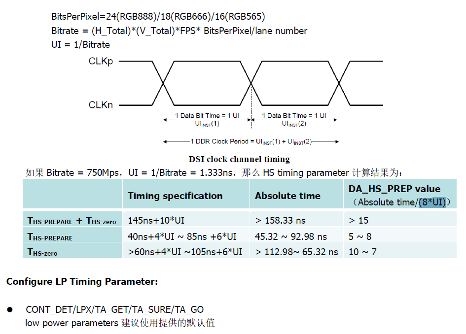
The calculation of m_wHsTrail, m_wHsPrpr, m_wHsZero, m_wClkHsPrpr, m_wClkHsExit, m_wClkTrail, m_wClkZero, m_wClkHsPost, m_wDaHsExit can refer to the table, you only need to fill in H_Total,V_Total,FPS,BitsPerPixel,lane number, the relevant data can be automatically calculated, and take the integer manually.
Formulas and concepts needed:
4. IMPORT PANEL PARAMETER
Add the filled ttl&mipi screen parameters to the project/board/m6/SSC016A-S01A/config/config.ini file, and include the current panel parameter items in m_pnlList.
Specify the panelType of DISP and Panel in the demo, and then run the demo on the board to light up the panel.
5. SPI PANEL
-
The kernel needs to enable the following two configs to open the spi driver:
CONFIG_SPI_SPIDEV=y
CONFIG_MS_SPI_INFINITY=y
-
dts configure spi related pin, kernel\arch\arm\boot\dts\infinity2m.dtsi
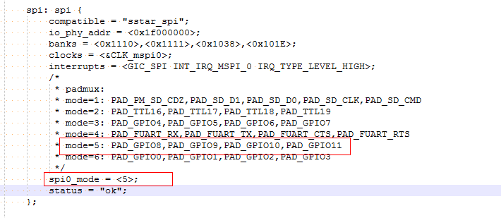
Note: These pins used by spi cannot be configured for other purposes in padmux.
-
Modify makefile
a. sdk\verify\feature\disp\config.mk
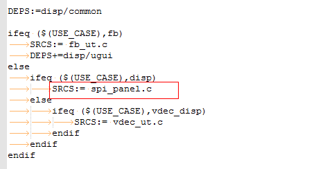
b. project\release\customer_tailor\nvr_i2m_display_glibc_tailor.mk

-
Compile spi panel demo
a. cd sdk/verify/feature
b. make clean;make disp
The compiled demo is in
sdk/verify/feature/disp/prog -
Put prog and 240_320_rgb565_20.bin in the same directory, execute
./progto light up the panel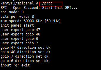
Note: The current demo pin configuration is as follows.
CS GPIO47
CS1 GPIO48
RST GPIO6
RS GPIO7

\\SPI related pins:
CZ GPIO8
CLK GPIO9
DI GPIO10
DO GPIO11
If there is a difference with the demo pin, you need to change the pin configuration in the following places in sdk\verify\feature\disp\spi_panel.c

6. FAQ
-
Close panel clk
/config/riu_w 0x1038 53 101
/config/riu_w 0x1038 63 1
-
Click to download panel list and Spread Spectrum Calculation