SSD_Padmux Instructions
1. What is Padmux
Padmux is a linux platform driver located in kernel\drivers\sstar\padmux. Because of the multiplexing of gpio pins, usually the same gpio can be used for different functions, so we use the padmux driver to uniformly configure the gpio pin functions that need to be used when booting.
2. PadMux Driver Introduction
The Padmux driver is defined as follows:
2.  static struct platform_driver sstar_padmux_driver = {
3.      .driver     = {
4.          .name   = "padmux",
5.          .owner  = THIS_MODULE,
6.          .of_match_table = sstar_padmux_of_match,
7.          .pm = &sstar_padmux_pm_ops,
8.      },
9.      .probe      = sstar_padmux_probe,
10. };
2.1. sstar_padmux_of_match
Used to match the gpio table device that needs to be configured at boot:
2.2. sstar_padmux_pm_ops
Implement the resume and suspend functions corresponding to str standby:
1.  static const struct dev_pm_ops sstar_padmux_pm_ops = {
2.      .suspend_late = sstar_padmux_suspend,
3.      .resume_early  = sstar_padmux_resume,
4.  };
2.3. sstar_padmux_probe
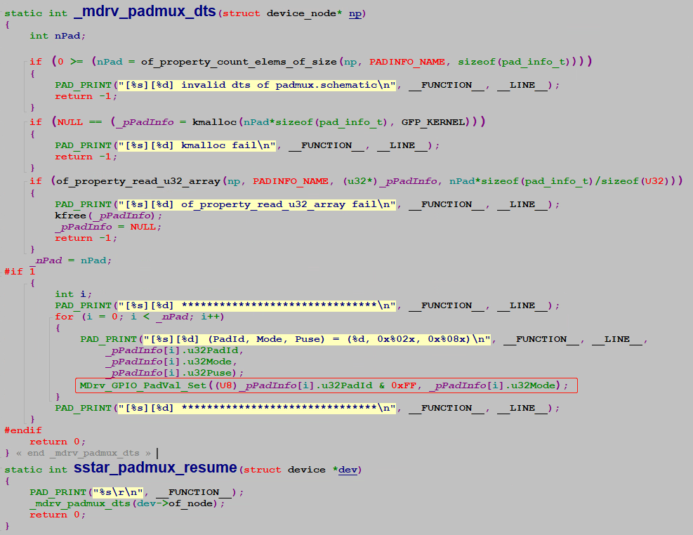
After matching the padmux device, the system will call sstar_padmux_probe to configure the gpio function:
Finally, configure gpio to the corresponding function through MDrv_GPIO_PadVal_Set:
kernel\drivers\sstar\gpio mdrv_gpio.c
1.  int MDrv_GPIO_PadVal_Set(U8 u8IndexGPIO, U32 u32PadMode)
2.  {
3.      return MHal_GPIO_PadVal_Set(u8IndexGPIO, u32PadMode);
4.  }
kernel\drivers\sstar\gpio\infinity2m mhal_gpio.c
1.  int MHal_GPIO_PadVal_Set(U8 u8IndexGPIO, U32 u32PadMode)
2.  {
3.      return HalPadSetVal((U32)u8IndexGPIO, u32PadMode);
4.  }
kernel\drivers\sstar\gpio\infinity2m mhal_pinmux.c
1.  S32 HalPadSetVal(U32 u32PadID, U32 u32Mode)
2.  {
3.      if (FALSE == _HalCheckPin(u32PadID)) {
4.          return FALSE;
5.      }
6.      if(u32PadID>=PAD_ETH_RN && u32PadID <= PAD_SAR_GPIO3)
7.          return HalPadSetMode_MISC(u32PadID, u32Mode);
8.      return HalPadSetMode_General(u32PadID, u32Mode);
9.  }
10. static S32 HalPadSetMode_General(U32 u32PadID, U32 u32Mode)
11. {
12.     U32 u32RegAddr = 0;
13.     U16 u16RegVal  = 0;
14.     U8  u8ModeIsFind = 0;
15.     U16 i = 0;
16.
17.     for (i = 0; i < sizeof(m_stPadMuxTbl)/sizeof(struct stPadMux); i++)
18.     {
19.         if (u32PadID == m_stPadMuxTbl[i].padID)
20.         {
21.             u32RegAddr = _RIUA_16BIT(m_stPadMuxTbl[i].base, m_stPadMuxTbl[i].offset);
22.
23.             if (u32Mode == m_stPadMuxTbl[i].mode)
24.             {
25.                 u16RegVal = _GPIO_R_WORD_MASK(u32RegAddr, 0xFFFF);
26.                 u16RegVal &= ~(m_stPadMuxTbl[i].mask);
27.                 u16RegVal |= m_stPadMuxTbl[i].val; // CHECK Multi-Pad Mode
28.
29.                 _GPIO_W_WORD_MASK(u32RegAddr, u16RegVal, 0xFFFF);
30.
31.                 u8ModeIsFind = 1;
32. #if (ENABLE_CHECK_ALL_PAD_CONFLICT == 0)
33.                 break;
34. #endif
35.             }
36.             else
37.             {   //Clear high priority setting
38.                 u16RegVal = _GPIO_R_WORD_MASK(u32RegAddr, m_stPadMuxTbl[i].mask);
39.                 if (u16RegVal == m_stPadMuxTbl[i].val)
40.                 {
41.                     printk(KERN_INFO"[Padmux]reset PAD%d(reg 0x%x:%x; mask0x%x) t0 %s (org: %s)\n",
42.                            u32PadID,
43.                            m_stPadMuxTbl[i].base,
44.                            m_stPadMuxTbl[i].offset,
45.                            m_stPadMuxTbl[i].mask,
46.                            m_stPadModeInfoTbl[u32Mode].u8PadName,
47.                            m_stPadModeInfoTbl[m_stPadMuxTbl[i].mode].u8PadName);
48.                     if (m_stPadMuxTbl[i].val != 0)
49.                     {
50.                         _GPIO_W_WORD_MASK(u32RegAddr, 0, m_stPadMuxTbl[i].mask);
51.                     }
52.                     else
53.                     {
54.                         _GPIO_W_WORD_MASK(u32RegAddr, m_stPadMuxTbl[i].mask, m_stPadMuxTbl[i].mask);
55.                     }
56.                 }
57.             }
58.         }
59.     }
60.
61.     return (u8ModeIsFind) ? 0 : -1;
62. }
Find reg corresponding to gpio and mode which need to be configured in m_stPadMuxTbl. Take PAD_GPIO4 configured as PINMUX_FOR_PWM0_MODE_3 as an example:
When configured in dts padmux:
<PAD_GPIO4 PINMUX_FOR_PWM0_MODE_3 MDRV_PUSE_PWM0 >,
During probe, bit2 of register bank 0x103c offset 0x65 is set to 1 according to the register setting of m_stPadMuxTbl:
1.  #define CHIPTOP_BANK                            0x101E00
2.  #define REG_PWM0_MODE                           0x07
3.  #define REG_PWM0_MODE_MASK                      BIT0|BIT1|BIT2
4.  {PAD_GPIO4, CHIPTOP_BANK, REG_PWM0_MODE,  REG_PWM0_MODE_MASK,  BIT1|BIT0, PINMUX_FOR_PWM0_MODE_3},
You can check whether the setting takes effect by reading reg on the board: riu_r 0x101E 0xE bit0/bit1
3. How to use PadMux
Through the introduction of the padmux driver above, we know that as long as the padmux driver is enabled, and the pin to be configured and the corresponding mode are written in the dts, the function corresponding to the gpio will be configured when the padmux probe is turned on. It should be noted that the pamdux driver depends on the gpio driver, so both drivers must be built into the kernel. At present, the default configuration of the public board, gpio and padmux, have buildin enabled by default:
1. CONFIG_MS_GPIO=y
2. CONFIG_MS_PADMUX=y
The following describes how to configure the corresponding gpio function in the padmux of dts.
3.1. Which padmux dts file to use
Find the padmux dts file specified in the corresponding kernel config file according to the following config, for example:
kernel\arch\arm\configs\infinity2m_spinand_ssc011a_s01a_minigui_defconfig:
1. CONFIG_SS_DTB_NAME="infinity2m-spinand-ssc011a-s01a-display"
kernel\arch\arm\boot\dts\infinity2m-spinand-ssc011a-s01a-display.dts:
1. #include "infinity2m.dtsi"
2. #include "infinity2m-ssc011a-s01a-display.dtsi"
3. #include "infinity2m-ssc011a-s01a-padmux-display.dtsi"
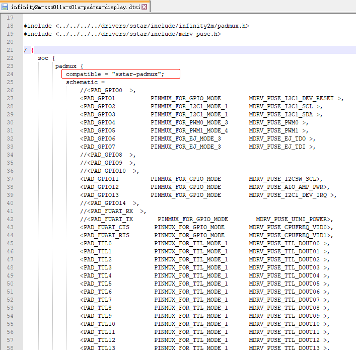
kernel\arch\arm\boot\dts\infinity2m-ssc011a-s01a-padmux-display.dtsi
3.2. Configure gpio mode
According to the hardware release information of the SDK release SSD201 HW Checklist V18.xlsx, find the padmux column:
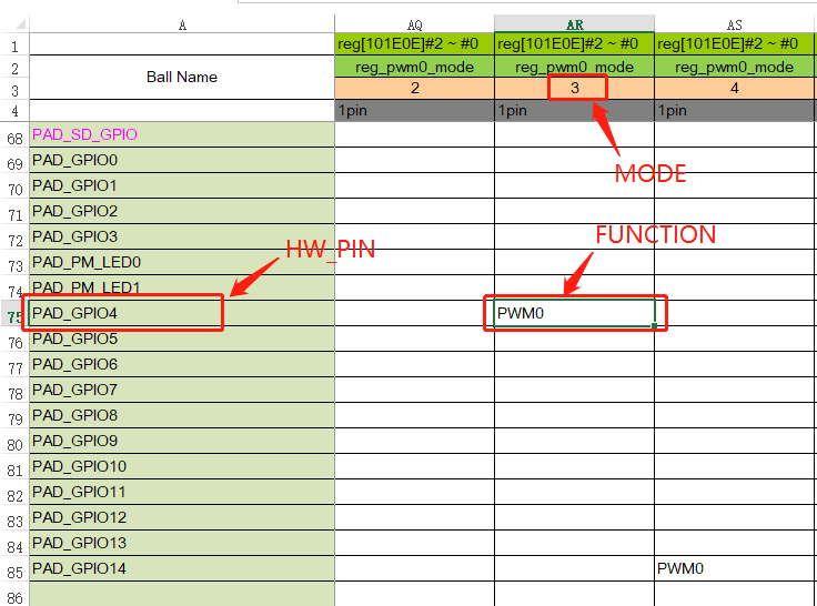
The above figure takes the configuration of PAD_GPIO4 as PWM0 as an example. It can be seen that PAD_GPIO4 can only be configured as pwm0 mode 3 to configure it as PWM0, so the configuration in padmux dts is as follows:
< PAD_GPIO4 PINMUX_FOR_PWM0_MODE_3 MDRV_PUSE_PWM0>,
Among them, MDRV_PUSE_PWM0 is generally only used as an explanation comment and has no special purpose unless the corresponding function driver has special settings. Other i2c, spi, uart, ttl, mipi settings can also refer to hw checklist configuration in padmux dts.
4. Notes
The same gpio pin can only be multiplexed into one function, and cannot be configured into two functions in padmux at the same time. If the function configured in padmux does not take effect, you need to confirm whether it is configured with other functions in dts.