SSD_PQ TOOL SOP
1. Tool Config & Connection
Click to download SSD_PQTool.rar.
-
Select the chip platform corresponding to SSD20X;
-
Select I2C-USB, and select the corresponding I2C address;
-
If the connection is successful, the icon changes from red to green. If it fails, please check the serial port connection.
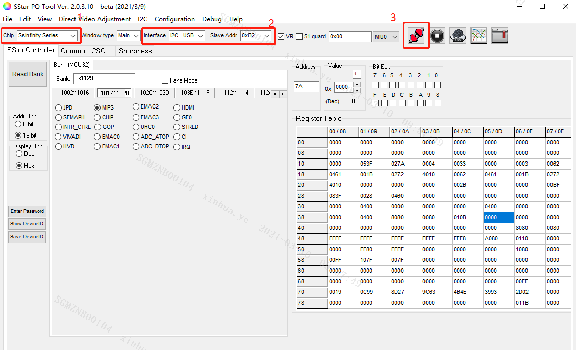
Figure1-1 Configuration and Connection
2. Verify Connection Status
After the connection is successful, read bank to confirm the connection status:
-
Select SStar Controller;
-
Select the corresponding bank address, and read bank: 0x1129;
-
Click Read Bank;
-
Confirm that the data in the Register Table is not all 0/0xFF.
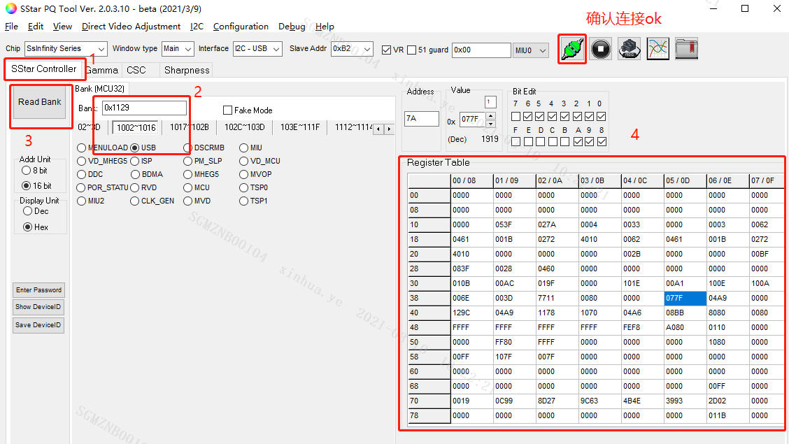
Figure2-1 Verify connection status
3. GAMMA Adjustment
3.1. Get the Current Gamma Value
-
Select Gamma;
-
Select Read;
-
Click Read to read the current Gamma config of the board;
-
Click Save to save the file, the file name generated by default is
Gamma_Parameter.txt.

Figure3-1 Get the current Gamma value
3.2. Adjust Gamma Value Online
-
Select Write;
-
Adjust Gamma curve or click Load to load the saved parameter(such as mark B on the following figure);
-
Click Write to write the updated Gamma data to the board;
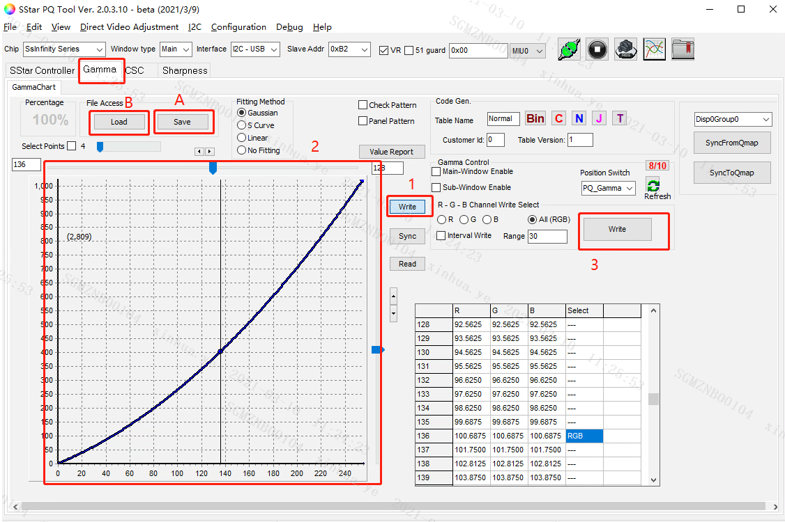
Figure3-2 Adjust Gamma value online
Parameter description:
-
Reset:after selecting Write, you can change the currently adjusted curve by right-clicking the mouse in the curve area and select Reset All Curve to reset to the default value;
-
Save is used to save the parameter values of the current tool, which is convenient for Load;
-
Load is used to import Saved parameter value and display it as curves.
4. CSC Adjustment
-
Select CSC;
-
Select Group, check Disp0Group1 by default;
SSD20X only has Disp0Group0/Disp0Group1. The CSC adjusted by Disp0Group0 will only affect Vedio but not UI, while Disp0Group1 will affect both of them.
-
Adjust CSC value;
Brightness: Bri
Saturation: Sat
Hue
Contrast
RGB gain
-
Click Download after adjustment, and the effect of CSC will be updated in real time;
-
Click GenMatrixTbl, the file
CSC_Parameter.txtis automatically generated in the root directory, and the debugged values are saved.
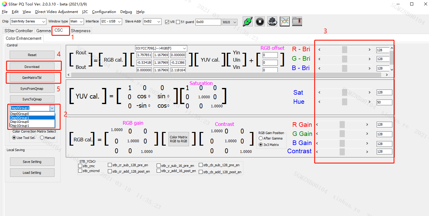
Figure5-1 CSC adjustment steps
Parameter description:
-
Reset is used to initialize parameters;
-
Save Setting is used to save the current parameters, which is convenient for Load Setting;
-
Load Setting is used to import and display the parameters of Save Setting.
5. Sharpness Adjustment
-
Select Sharpness;
-
Check 2D Peaking Enable;
-
Adjust B01/B02;
B01 is macro adjustment, B02 is fine adjustment, the range is 0-60, after adjustment, click enter to take effect.
-
Click Save Peaking to file, the default file name is
Sharp_Parameter.txt.

Figure6-1 Sharpness adjustment
Parameter description:
Peaking_Band_refresh (mark A on the figure) is used to read the value of B01/B02 currently set on the board.
6. Adjust PQ In Project
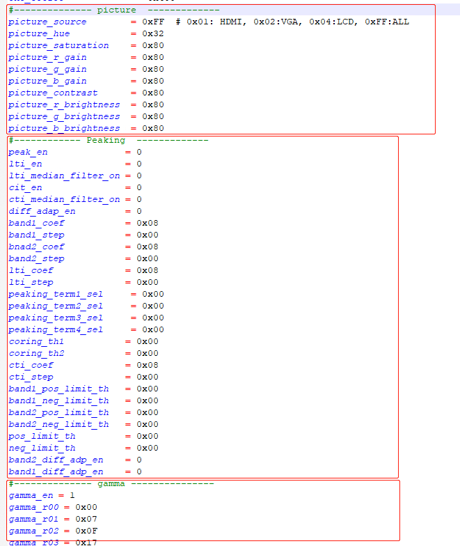
PQ Tool is only an online debugging method. When the desired effect is adjusted, you need to fill in the parameters of Gamma_Parameter.txt/CSC_Parameter.txt/Sharp_Parameter.txt adjusted and saved by Gamma/CSC/Sharness into the corresponding file:
a. In the Uboot stage, through boot/drivers/mstar/disp/mhal/pub/pq.h, select the option that needs to be enabled, and then fill in the corresponding parameters into the corresponding structure.

b. After the Kernel is up, fill in the corresponding parameter data into the project/borad/ini/pq.ini file in the project. In the boot script demo.sh, use echo pq.ini 0x148 > /sys/class/mstar/mdisp /pq to achieve the effect of automatically updating the PQ each booting.
Note: The parameters of pq.h in the Uboot stage should be the same as the parameters of pq.ini after the kernel is up. Otherwise, if there is a bootlogo, the bootlogo will obviously feel the color flashing from the uboot stage to the kernel stage during the booting.