I2C Reference
1. Overview
SSD20x provides two sets of HW I2C, as shown in the following table: (please refer to Hw_Checklist):
-
HW I2C GROUP0 can choose one of the following 4 types, and the corresponding node is /dev/i2c-0.
-
HW I2C GROUP1 can choose one of the following 5 types, and the corresponding node is /dev/i2c-1.
| BUS | DEV | MODE | SCL | SDA |
|---|---|---|---|---|
| HW I2C GROUP0 | /dev/i2c-0 | MODE1 | PAD_HDMITX_SCL | PAD_HDMITX_SDA |
| MODE2 | PAD_TTL1 | PAD_TTL2 | ||
| MODE3 | PAD_TTL14 | PAD_TTL15 | ||
| MODE4 | PAD_GPIO6 | PAD_GPIO7 | ||
| HW I2C GROUP1 | /dev/i2c-1 | MODE1 | PAD_GPIO2 | PAD_GPIO3 |
| MODE2 | PAD_HDMITX_SCL | PAD_HDMITX_SDA | ||
| MODE3 | PAD_FUART_CTS | PAD_FUART_RTS | ||
| MODE4 | PAD_TTL22 | PAD_TTL23 | ||
| MODE5 | PAD_SD_CLK | PAD_SD_CMD |
2. Config Instructions
2.1. I2C Config in Kernel
2.1.1. Config
CONFIG_I2C (enbled by default)
CONFIG_MS_I2C (enbled by default)
The kernel driver adopts the general device tree config method, and modify the corresponding dts according to the config of each project.
2.1.2. Padmode Configure
Take HW I2C GROUP0, MODE1 as an example(Please select the dtsi file used by the project for config)
-
Open
kernel\arch\arm\boot\dts\infinity2m-ssc011a-s01a-display.dtsi, configure i2c-group as i2c-0 and i2c-padmux as 1, which means MODE1 is selected.
-
Add padmux settings, open
kernel\arch\arm\boot\dts\infinity2m-ssc010a-s01a-padmux-display.dtsi, for SSD20X, when i2c-0 selects mode1, the corresponding pin is PAD_HDMITX_SCL/PAD_HDMITX_SDA.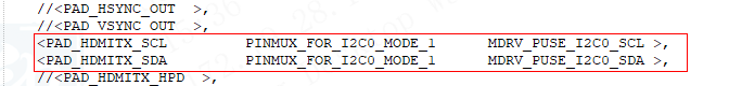
2.2. I2C Config of Uboot
2.2.1. Padmode Configure
-
Open
boot\include\configs\infinity2m.hto configureCONFIG_SYS_I2C_0_PADMUX/CONFIG_SYS_I2C_1_PADMUX, which means the mode setting of I2C-0/I2C-1 is selected, and the mode here can match the kernel.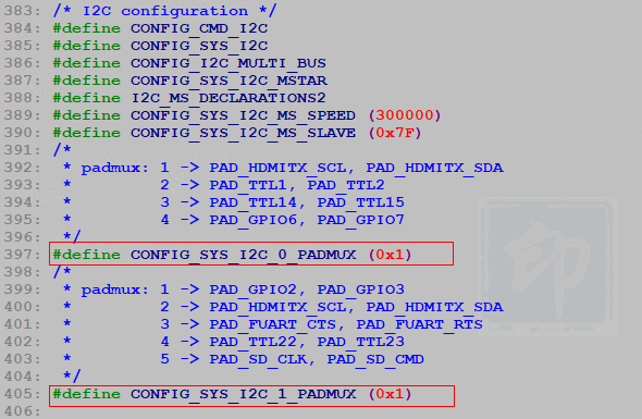
3. How to use I2C
The following is only a basic interface example, please refer to the demo for the detail.
3.1. Read and Write I2C in Kernel
-
Open the device, FILE_NAME can be "/dev/i2c-0" or "/dev/i2c-1"

-
Read interface

-
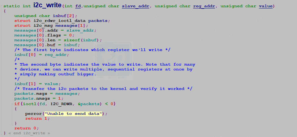
Write interface
3.2. Read and Write I2C in Uboot
Uboot has been connected to the standard interface.
Reference:alkaid\boot\common\cmd_i2c.c
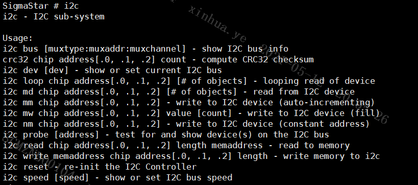
Test command description:
-
Select bus, optional 0 and 1: i2c dev 1
-
Probe the device on the corresponding bus: i2c probe
-
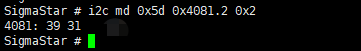
Read the device data and print the value directly on the serial port:
i2c md slave_id reg_adrr.len size// *slave_id: device id // *reg_addr: Device register address to be read // *len: Bytes of reg_addr (1/2 byte) // *size: The length of the data to be read back
Examples of touch control IC for SSD20X evaluation version Demo board:
The slave_id of the touch IC is 0x5D, reg_addr is 0x4081 (2 bytes), i2c md 0x5D 0x4081.2 0x2.