SSD_Ethernet Reference
1. Overview
1.1. Introduction to Ethernet Architecture
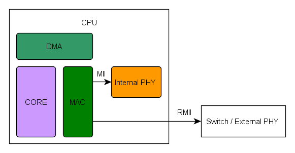
From the hardware point of view, the Ethernet interface circuit is mainly composed of a MAC (Media Access Control) controller and a physical layer interface PHY (Physical Layer, PHY). The Sigmastar platform has a built-in MAC controller and a built-in PHY; it also supports the RMII bus protocol, which can be connected to an external switch or PHY chip. The diagram is as follows:
1.2. RMII interface introduction
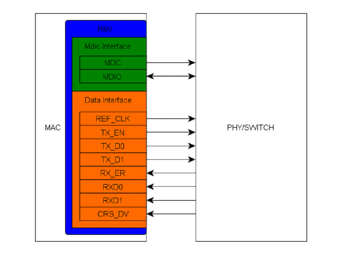
The RMII interface includes a data interface, and a management interface between the MAC and the PHY. The MDIO management interface includes two signal lines (MDC and MDIO). Through this interface , the MAC can read the PHY or Switch chip registers to achieve transmission information and status control.
1.3. Using RMII under uboot
SSD2XX platform example
1.3.1. Enable RMII support under uboot
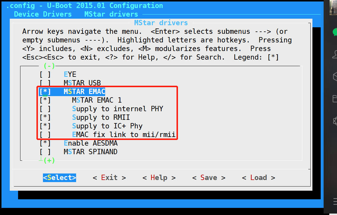
Enable emac in menuconfig, close the built-in phy and open the rmii interface, as follows:
1.3.2. Use MDIO to initialize PHY or Switch
mdio read and write function are provided under uboot , see the file: boot/drivers/mstar/emac/pioneer3/mhal_emac.c
MDIO read:
void MHal_EMAC_read_phy(unsigned char phy_addr, unsigned char address, u32 *value)
MDIO write:
void MHal_EMAC_write_phy (unsigned char phy_addr, unsigned char address, u32 value)
Please refer to the ip101a_g_config_init function in the boot/drivers/mstar/emac/mdrv_emac.c file, initialize the external PHY or Switch chip using mdio read/write to access registers.
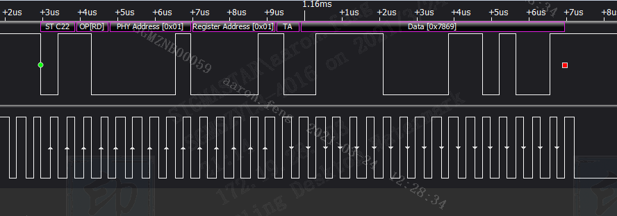
It should be noted that during the read operation, the MDC clock on the master side will become the falling edge sampling after the TA signal, as shown in the figure below; the write operation will always keep the rising edge sampling. To determine whether the MDIO is read and written correctly, a logic analyzer can be used to capture the MDIO and MDC signal waveforms.
1.4. Using RMII under the kernel
SSD20X platform example
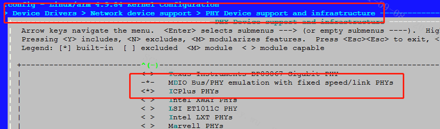
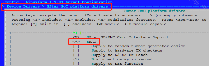
1.4.1. Open network support in kernel
Open the following options in menuconfig:
1.4.2 Configure RMII pin PINMUX
Open the kernel\arch\arm\boot\dts\infinity2m-xxxxx-padmux-display.dtsi file, and add the following content to the padmux field:
<PAD_TTL16           PINMUX_FOR_ETH1_MODE_3      MDRV_PUSE_NA >,
<PAD_TTL17           PINMUX_FOR_ETH1_MODE_3      MDRV_PUSE_NA >,
<PAD_TTL18           PINMUX_FOR_ETH1_MODE_3      MDRV_PUSE_NA >,
<PAD_TTL19           PINMUX_FOR_ETH1_MODE_3      MDRV_PUSE_NA >,
<PAD_TTL20           PINMUX_FOR_ETH1_MODE_3      MDRV_PUSE_NA >,
<PAD_TTL21           PINMUX_FOR_ETH1_MODE_3      MDRV_PUSE_NA >,
<PAD_TTL22           PINMUX_FOR_ETH1_MODE_3      MDRV_PUSE_NA >,
<PAD_TTL23           PINMUX_FOR_ETH1_MODE_3      MDRV_PUSE_NA >,
<PAD_TTL24           PINMUX_FOR_ETH1_MODE_3      MDRV_PUSE_NA >,
<PAD_TTL25          PINMUX_FOR_GPIO_MODE MDRV_PUSE_EMAC1_PHY_RESET>,
1.4.3 Modify device tree to enable RMII
Open the kernel\arch\arm\boot\dts\infinity2m.dtsi file, modify the following content, and configure the phy-mode as the rmii interface.
emac1: emac1 {
            compatible = "sstar-emac";
            interrupts = <GIC_SPI INT_IRQ_EMAC_1 IRQ_TYPE_LEVEL_HIGH>, <GIC_SPI INT_FIQ_LAN_ESD IRQ_TYPE_LEVEL_HIGH>;
            clocks = <&CLK_emac_ahb>,<&CLK_emac1_tx>,<&CLK_emac1_rx>,<&CLK_emac1_tx_ref>,<&CLK_emac1_rx_ref>;
            reg = <0x1F2A2800 0x800>, <0x1F344200 0x600>, <0x00000000 0x000>;
            pad = <0x1F203C38 0x0F00 0x0300>; // pad selection from 0x0100/0x0200/0x0300/0x0400/0x0500/0x0600/0x0700/0x0800/0x0900
            status = "ok";
#if 1
            phy-handle = <&phy1>;
            mdio-bus@emac1 {
                phy1: ethernet-phy@1 {
                    phy-mode = "rmii";
                };
            };
#else
            phy-mode = "rmii";
            fixed-link = <0 1 100 0 0>;
#endif
1.4.4 Initialize PHY or Switch through MDIO interface
Kernel also supports mdio read and write operations, as follows:
MDIO read function:
MDev_EMAC_mii_read
MDIO write function:
MDev_EMAC_mii_write
MII/RMII initialization function:
MDev_EMAC_mii_init
For the specific code, see the kernel/drivers/sstar/emac/mdrv_emac.c file. The function for users to initialize the PHY or Switch chip can be added after the MDev_EMAC_mii_init function.
static int MDev_EMAC_mii_write(struct mii_bus *bus, int phy_addr, int phy_reg, u16 val)
{
    struct emac_handle *hemac = (struct emac_handle *) bus->priv;
    int ret;

    ret = MHal_EMAC_write_phy(hemac->hal, phy_addr, phy_reg, (u32)val);
    return ret;
}

static int MDev_EMAC_mii_read(struct mii_bus *bus, int phy_addr, int phy_reg)
{
    u32 val;
    struct emac_handle *hemac = (struct emac_handle *) bus->priv;
    int ret;

    ret = MHal_EMAC_read_phy(hemac->hal, phy_addr, phy_reg, &val);
    return (int)val;
}

static int MDev_EMAC_mii_init(struct net_device* emac_dev)
{
    struct emac_handle *hemac = (struct emac_handle *) netdev_priv(emac_dev);
    struct device_node *mii_np = NULL;
    int ret = 0;

    ...

    hemac->mii_bus->name = "mdio";
    hemac->mii_bus->read = MDev_EMAC_mii_read;
    hemac->mii_bus->write = MDev_EMAC_mii_write;
    hemac->mii_bus->priv = hemac;
    hemac->mii_bus->parent = hemac->dev;

    ...

    return ret;
}
2. ETHERNET Common Config
2.1. Configure IP address under uboot and kernel
Use the following commands to set the IP of the board and the IP of the computer under uboot, and use the ping command to test whether the network is connected:
SigmaStar # setenv ipaddr 192.168.50.123

SigmaStar # setenv serverip 192.168.50.249

SigmaStar # ping 192.168.50.249

Using sstar_emac device

host 192.168.50.249 is alive
Use the ifconfig command to configure IP-related properties under kernel:
/ # ifconfig eth0 up

/ # ifconfig eth0 hw ether 00:70:27:00:00:03

/ # ifconfig eth0 192.168.50.123 netmask 255.255.255.0

/ # route add default gw 192.168.50.1
2.2. Obtaining IP automatically using DHCP
The script file is located in the project directory project/image/etc/init.d/udhcpc.script. When the image is packaged, it will be copied to the board. After the kernel is up, the board will run the udhcpc command to automatically obtain the ip. The example is as follows:
/ # udhcpc -i eth0 -s /etc/init.d/udhcpc.script
udhcpc (v1.20.2) started
Setting IP address 0.0.0.0 on eth0
Sending discover...
Sending discover...
Sending select for 192.168.50.243...
Lease of 192.168.50.243 obtained, lease time 86400
Setting IP address 192.168.50.243 on eth0
Deleting routers
route: SIOCDELRT: No such process
Adding router 192.168.50.1
Recreating /appconfigs/resolv.conf
Adding DNS server 192.168.50.1
2.3. DNS Service Usage
2.3.1 Prepare DNS dependency library
To open the DNS service, you need to depend on the relevant library files, which can be copied from the toolchain to the board, and the dynamic library can be exported using the export command.
/ # export LD_LIBRARY_PATH=$LD_LIBRARY_PATH:/lib/libdns
For example, if you are using the 9.1.0 toolchain, the relevant library files are in the following directory:
/tools/toolchain/gcc-sigmastar-9.1.0-2020.07-x86_64_arm-linux-gnueabihf/arm-linux-gnueabihf/libc/lib/

libnsl-2.30.so
libnsl.so.1
libnss_compat-2.30.so
libnss_compat.so.2
libnss_db-2.30.so
libnss_db.so.2
libnss_dns-2.30.so
libnss_dns.so.2
libnss_files-2.30.so
libnss_files.so.2
libnss_hesiod-2.30.so
libnss_hesiod.so.2
libresolv-2.30.so
libresolv.so.2
2.3.2 Configure DNS Server
Create the /etc/resolv.conf configuration file on the board and write the corresponding dns server ip, such as:
/ # echo "nameserver 8.8.8.8" >> /etc/resolv.conf
2.3.3 Test DNS
Use the ping command to test the DNS resolution domain name, such as:
/ # ping www.baidu.com
PING www.baidu.com (163.177.151.109): 56 data bytes
64 bytes from 163.177.151.109: seq=0 ttl=55 time=7.640 ms
64 bytes from 163.177.151.109: seq=1 ttl=55 time=8.002 ms
64 bytes from 163.177.151.109: seq=2 ttl=55 time=7.443 ms
--- www.baidu.com ping statistics ---
3 packets transmitted, 3 packets received, 0% packet loss
round-trip min/avg/max = 7.443/7.695/8.002 ms
3. ETHERNET Bandwidth Test Instructions
3.1. Use iperf to test network performance
3.1.1. Download iperf source code
Linux side download address:
https://iperf.fr/download/source/iperf-2.0.9-source.tar.gz
PC side download address:
https://iperf.fr/iperf-download.php#windows
Note: The version of iperf on the linux side is the same as that on the PC side
3.1.2 Compile iperf
Configure the cross compiler:
./configure --help ./configure --prefix=$(pwd)/host --host=arm-linux-gnueabihf CXX=arm-linux-gnueabihf-g++ CC=arm-linux-gnueabihf-gcc
After Compiling and installation, the executable file iperf will be generated in the current directory host/bin and copied to the board:
make clean
make -j4
make install
3.1.3 Test network
Help command:
/ # ./iperf –h
-f [k|m|K|M], means to display the report in Kbits, Mbits, KBytes, MBytes respectively, the default is in Mbits
-i sec, display report interval in seconds, eg: iperf -c 222.35.11.23 -i 2
-l buffer size, the default is 8KB, eg: iperf -c 222.35.11.23 -l 16 -m Display the maximum mtu value of tcp
-o output reports and error messages to a file, eg: iperf -c 222.35.11.23 -o /mnt/iperflog.txt
-p specifies the port used by the server or the port the client is connected to
-u use udp protocol
-w specifies the TCP window size, the default is 8KB
-M Set the maximum mtu value of TCP packets
Client-side dedicated parameters:
-d Simultaneous bidirectional transmission test
-n specifies the number of bytes to transfer, eg: iperf -c 222.35.11.23 -n 100000
-r Test for bidirectional transmission alone
-t test time, the default is 10 seconds, eg: iperf -c 222.35.11.23 -t 5
-F specifies the file to transfer
-T specifies the ttl value
3.1.4 TCP throughput test
The PC side is used as the server, and the board side is used as the client. Open the cmd command line in Windows and enter iperf -s to run iperf in server mode, as shown in the following figure:
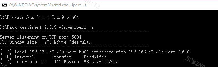
On the Linux board, run iperf in client mode and test for 10 seconds, as follows:
/ # ./iperf -c 192.168.50.249 -i 1 -t 10
-------------------------------------------------- ------------
Client connecting to 192.168.50.249, TCP port 5001
TCP window size: 128 KByte (default)
-------------------------------------------------- ------------
[ 3] local 192.168.50.243 port 49902 connected with 192.168.50.249 port 5001
[ID] Interval Transfer Bandwidth
[ 3] 0.0- 1.0 sec 11.1 MBytes 93.3 Mbits/sec
[ 3] 1.0- 2.0 sec 11.2 MBytes 94.4 Mbits/sec
[ 3] 2.0- 3.0 sec 11.0 MBytes 92.3 Mbits/sec
[ 3] 3.0- 4.0 sec 11.2 MBytes 94.4 Mbits/sec
[ 3] 4.0- 5.0 sec 11.2 MBytes 94.4 Mbits/sec
3.1.5 UDP packet loss test
The PC side is used as the server, and the board side is used as the client. Open the cmd command line in Windows, enter iperf -s -u to run iperf in server mode, as shown in the following figure:
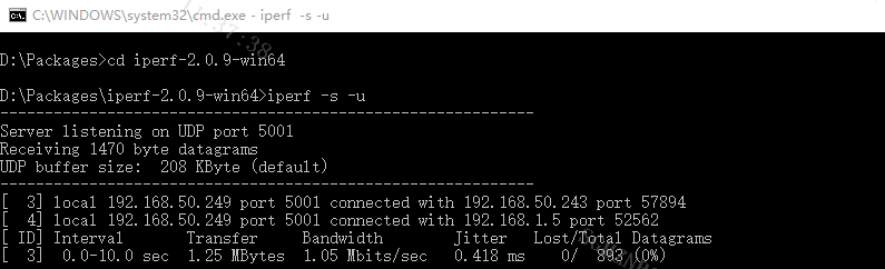
On the Linux board, run iperf in client mode and test for 10 seconds, as follows:
/ # ./iperf -c 192.168.50.249 -i 1 -t 10 -u
------------------------------------------------------------
Client connecting to 192.168.50.249, UDP port 5001
Sending 1470 byte datagrams, IPG target: 11215.21 us (kalman adjust)
UDP buffer size:  512 KByte (default)
------------------------------------------------------------
[  3] local 192.168.50.243 port 57894 connected with 192.168.50.249 port 5001
[ ID] Interval       Transfer     Bandwidth
[  3]  0.0- 1.0 sec   131 KBytes  1.07 Mbits/sec
[  3]  1.0- 2.0 sec   128 KBytes  1.05 Mbits/sec
[  3]  2.0- 3.0 sec   128 KBytes  1.05 Mbits/sec
[  3]  3.0- 4.0 sec   128 KBytes  1.05 Mbits/sec
[  3]  4.0- 5.0 sec   128 KBytes  1.05 Mbits/sec
[  3]  5.0- 6.0 sec   128 KBytes  1.05 Mbits/sec
[  3]  6.0- 7.0 sec   129 KBytes  1.06 Mbits/sec
[  3]  7.0- 8.0 sec   128 KBytes  1.05 Mbits/sec
[  3]  8.0- 9.0 sec   128 KBytes  1.05 Mbits/sec
[  3]  9.0-10.0 sec   128 KBytes  1.05 Mbits/sec
[  3]  0.0-10.0 sec  1.25 MBytes  1.05 Mbits/sec
[  3] Sent 893 datagrams
[  3] Server Report:
[  3]  0.0-10.0 sec  1.25 MBytes  1.05 Mbits/sec   0.417 ms    0/  893 (0%)
4. Typical FAQ Example
Q: How to add the network port driver capability of ephy?
For [SSD20X][SSD212][SSD22X]
riu_r 0x31 0x2E
riu_w 0x31 0x2E 0x7001 //Set bit0 to 1
echo swing_100 2 > /sys/devices/virtual/mstar/emac0/turndrv //Enhance network port driver capability
riu_r 0x33 0x42 //View the current network drive amplitude
Q: What if there are some extra long network cables (>200m)?
For [SSD20X][SSD212][SSD22X]
The transmission distance of more than 100m is out of specification, and reliability cannot be guaranteed, but you can try to limit the speed to 10M.
riu_w 0x31 0x04 0x61
riu_w 0x31 0x00 0x1200
echo max > /sys/class/mstar/emac0/turndrv