SSD_FUART & UART Traffic Control Usage
1. Fuart Traffic Control Process
1.1. HW Connection

1.2. Parameters Description
-
RTS
Require To Send. The send request is an output signal used to indicate that the device is ready to receive data. Active low, indicating that the device can receive data.
-
CTS
Clear To Send. Allows to send input signals, used to determine whether data can be sent to the other side. Active low, indicating that the device can send data to the other side.
1.3. Traffic Control Method
If our side processes the data stream (receives data from the other side), set RTS to low; if the CTS pin of the other side device is low level, data can be sent.
If our side does not process the data stream (does not receive data from the other side), set RTS to high; if the CTS pin of the other side device is high, stop sending data and wait for the pin of CTS to change.
1.4. Notes
-
Confirm that the pin is configured with Fuart
kernel\arch\arm\boot\dts\infinity2m-ssc011a-s01a-padmux-display.dtsi :
<PAD_FUART_RX PINMUX_FOR_FUART_MODE_1 MDRV_PUSE_FUART_RX>,
<PAD_FUART_TX PINMUX_FOR_FUART_MODE_1 MDRV_PUSE_FUART_TX>,
<PAD_FUART_CTS PINMUX_FOR_FUART_MODE_1 MDRV_PUSE_FUART_CTS>,
<PAD_FUART_RTS PINMUX_FOR_FUART_MODE_1 MDRV_PUSE_FUART_RTS>,
kernel\arch\arm\boot\dts\infinity2m-ssc011a-s01a-padmux-display.dtsi :
fuart: uart2@1F220400 { compatible = "sstar,uart"; reg = <0x1F220400 0x100>, <0x1F220600 0x100>; interrupts = <GIC_SPI INT_IRQ_FUART IRQ_TYPE_LEVEL_HIGH>, <GIC_SPI INT_IRQ_URDMA IRQ_TYPE_LEVEL_HIGH>; clocks = <&CLK_fuart>; dma = <0>; sctp_enable = <1>;//rts cts enable is 1 //pad = <PAD_FUART_RX>;//fuart mode2 pad = <PAD_FUART_CTS>;//fuart mode 1 tolerance = <2>; status = "ok"; }; -
Confirm that the software has enabled cts/rts, if not, the default value is high.
-
If you want to ensure that ssd20x is in an acceptable state, use the command: cat /dev/ttyS2 &. If the ttyS2 device is not always enabled, the interrupt status of Fuart will be automatically cleared. Obtain register[101e 2]==0x0000; the normal value is 0x0005.
2. Connect to RS485 chip, half-duplex communication process
-
Connection method
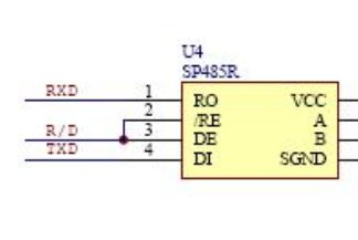
RS485 is the master-salver mode, mater is the initiator, and salmon is the responder. There is only one device in the network sending data, and the others are in the monitoring state.
The main process is as follows, all actions need to wait for the master to notify.
When Host/Master sends data to RS485, first pull R/D high, after sending, pull R/D low, Host/Master enters the monitoring state and waits for slaver's response.
-
How to use APP layer
struct serial_rs485 rs485conf;

memset(&rs485conf,0,sizeof(rs485conf));

rs485conf.padding[0] = 17;   //Control the gpio index sent and received by slaver
rs485conf.delay_rts_after_send = 2000;  // The delay time required to send the last byte, unit: us
rs485conf.flags |= SER_RS485_RTS_ON_SEND; //Pull up gpio before sending, and open SER_RS485_RTS_AFTER_SEND means pulling up after sending
rs485conf.flags |= SER_RS485_ENABLED; // Enable the 485 mode of this serial port, disabled by default
ioctl(iHandle, TIOCSRS485, &rs485conf);