SSD_BOOTLOGO Reference
1. OVERVIEW
This article provides methods to add, delete, and modify the Boot logo in the SDK compilation environment.
Note before changing the logo:
-
Now, bootlogo only supports jpg image format, because it is software decoding, so the larger the image, the slower the decoding speed. The default bootlogo buffer assigned by the public version is 1M, the resolution of the image needs to meet width*height*1.5\<1M; the size of the image should be small 128KB than the logo partition.
-
The width of the picture needs to be 16 aligned.
2. BOOT LOGO DISPLAY PRINCIPLE
A set of drivers to decode JPG and display has been implemented in Uboot, which use bootcm to display the BOOT LOGO.
BOOT LOGO display steps are as following:
-
Grab screen parameters or HDMI/VGA display related information and original JPEG data from the fixed LOGO partition.
-
Display how many screen parameters data are saved in related information, uboot will find the corresponding screen parameter data according to the name in the current env.
-
The original JPGE data supports multiple, and the JPGE to be displayed can be dynamically switched according to user parameters.
-
The display information also provides the buffer address used by uboot for display, as well as the panel resolution and display refresh rate.
-
Send JPEG RAW data to decoder for decoding.
-
There are two ways to use the data decoded by the decoder for display. One is to decode the YUV420 data for DISP display, the displayed content is in the video layer, and the other is to decode the ARGB8888 format and send it to GOP, the displayed content is in the graphics layer.
-
Initialize HDMI and Panel, display BOOT LOGO.
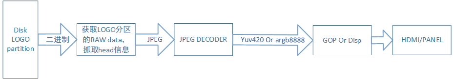
Figure2-1
3. BOOT LOGO CONFIG
3.1. Enable bootlogo hdmi
-
Uboot:
Open the following config:
CONFIG_CMD_BOOTLOGO
CONFIG_SSTAR_DISP
CONFIG_SSTAR_DISP_HDMITX_VGA
CONFIG_SSTAR_HDMITX
CONFIG_SSTAR_JPD
If hdmi is used, the
CONFIG_ANALOG_PD_HDMI_ATOPof the kernel needs to be turned off, otherwise the logo will disappear when the kernel boots up.
3.2. Enable Bootlogo Panel
-
Uboot:
Open the following config:
CONFIG_CMD_BOOTLOGO
CONFIG_SSTAR_DISP
CONFIG_SSTAR_PNL
CONFIG_SSTAR_JPD
4. LOGO Partition Description
Uboot will first read the partition of the current "LOGO" field. If it exists, it will read the screen parameter information in the LOGO partition and the corresponding logo image data for display operation.
Logo uses the LOGO bare partition. The following table lists several characteristics of the LOGO partition.
| Features | LOGO Partition |
|---|---|
| Dynamic support for screen parameter change | Support |
| Dynamic modification of screen parameters | Not supported |
| Dynamic modification of boot logo image | Not supported |
| Screen parameter data analysis time (estimated) | 55ms |
| Whether to share screen parameters with LINUX | No |
| Support mount on Linux | Not supported |
| Partition size (spinand) | 384KB |
5. LOGO PARTITION PRODUCTION
5.1. Basic Structure Of LOGO Partition
![]()
Figure5-1
The LOGO partition is divided into partition header and several sub headers.
Partition header stored sub header count and tittle.
Sub header has two kinds of data, one of which is to save the data of screen parameters and HDMI/VGA display parameters. These data are saved in Flash in the form of C language structure. The other is that several Sub headers store Jpeg pictures.
In the display data, Frist_use_offset is used to index the current default screen parameters or the setting of hdmi/vpa.
5.2. Project Boot LOGO Configuration (LOGO partition)
The modification of BOOT LOGO is based on that the LOGO partition has been created, and the display device (display out: panel/HDMI/VGA) has been configured. On this basis, the display device designated in the LOGO partition, the memory address used for display and the file name of the boot LOGO can be modified.
-
Open build config file to modify the followings:
BOOTLOGO_FILE = sigmastar1024_600.jpg
BOOTLOGO_ADDR = E_LX_FB
DISP_OUT_NAME = SAT070CP50
-
BOOTLOGO_FILE means to use the corresponding file name for logo display under project\board\ini\misc\.
-
BOOTLOGO_ADDR is used to display the memory address.
-
DISP_OUT_NAME displays the output name used, how to make it can refer to LOGO PARTITION PRODUCTION.
5.3. LOGO Partition Production Source Code And Tool Usage
The source code path generated by the RAW data partition of the LOGO is:
project\image\makefiletools\src\rawgenerator
Executing make under this path will automatically copy the executable bin to project\image\makefiletools\bin\ to generate the corresponding LOGO image during compilation.
The script generated by the LOGO partition:
project\image\image.mk
![]()
Figure5-2
The image of LOGO is generated by dispcfggen and logogen, dispcfggen generates display-related parameter data, and logogen generates LOGO data composed of images.
The code path of display data:
project\image\makefiletools\src\rawgenerator\disp_data_main.c
The code path of Jpeg image
project\image\makefiletools\src\rawgenerator\logo_data_main.c
Description of using parameters:
dispcfggen:
-c: create a header for raw data and add displayed subheader and data. If the file specified by -o exists, clear the file.
-a: add a display related subheader and data to the end of the file which have raw data header and data.
-o: specify the output file.
-p: Physical address for display on the board.
-s: display the memory size of the address
-d: display output index name
logogen:
-c: create a header for raw data and add subheader and data for jpeg format files. If the file specified by -o exists, clear the file.
-a: add subheader and data of a jpeg format file to the end of the file which have raw data header and data.
-o: specify the output file.
-i: path of jpeg file.
5.4. Modify Display Data
The display data is divided into two parts, one is screen parameters for panel display, the other is HDMI/VGA display output, these two attributes are mutually exclusive in use, once the user sets DISP_OUT_NAME as the screen parameter The name of the output display data is all screen parameter data. If the name starts with HDMI/VGA, only the parameter data of HDMI/VGA will be output, such as HDMI_1080P60.
5.4.1. Modify Screen Parameter
-
Prepare the screen parameter file (if you have any questions about the screen parameter file configuration, you can consult with FAE)
-
The screen parameter file is an initialized structure data, which is stored in an h file. All screen parameter files used in the public version are stored in
project\image\makefiletools\src\rawgenerator\pnl. Note: The data structure name declared in the header file of each screen parameter must not be the same asdefine, otherwise the compilation will fail. -
Modify or add stTable in
disp_data_main.c, specify the screen parameter name, data structure and mipi command data structure. Note: ttl has no mipi parameter, so fill in NULL in the mipi column.
Figure5-3
-
Screen parameter include:
Figure5-4
-
After the above modification is completed, recompile and generate the executable file, the logo image generated by execution file has the added screen parameter, use
-dto specify the name of the preferred screen parameter. If the preferred screen parameter is incorrect, modify it by modifyingenvin uboot. Refer to "Multi-screen parameter and multi-logo switching".
5.4.2. Modify HDMI/VGA Setting
-
HDMI/VGA only needs to fill in the width and height of the output timing and clock.
-
The modification method is as follows:

Figure5-5
5.5. Multi-display Parameter Switching
All the display parameter data is saved in the partition of LOGO, which can be switched by env.
Use the index of display settings in uboot's env ${dispout}. By default, env is empty. After the first power-on, if the bootlogo command is executed in the uboot phase, the name corresponding to the currently used setting will be saved to ${dispout}.
‘Bootlogo’ command execution flow chart:
![]()
Figure5-6
As you can see from the figure above, if the environment variable ${dispout} is not specified, the system will set the preferred display parameters by default.When ${dispout} is inconsistent with the preferred display parameter, the system will automatically index the corresponding display parameter according to the value set by ${dispout}.If found, it will be written back to the flash, so that the next boot process will be executed according to the process matching the environment variables.
6. UBoot COMMAND
6.1. Bootlogo Command Introduction
Execute bootlogo [logo index] [aspect ratio] [x] [y] in Uboot.
The four parameters represent:
-
The digital index of the JPEG packaged in the LOGO.
-
Display the aspect ratio of logo, 0: zoom, full-screen display, 1: center, center display, 2: user, user sets the starting point, point to point display.
-
If the aspect ratio is user, x and y represent the starting point of the displayed image.
6.2. LOGO Rotation
Modify env ‘logo_rot’ in uboot, restart after modification, or execute bootlogo command again.
logo_rot = 0 : no rotation
logo_rot = 1 : Rotate 90° clockwise
logo_rot = 2 : Rotate 180° clockwise
logo_rot = 3 : Rotate 270° clockwise
After the LOGO rotation, the upper left corner of the screen is still displayed from (0, 0). The width and height of the image may be exchanged.
Note: The rotated image must be in the displayed area, otherwise the display driver will report an error.
7. sd/usb UPGRADE UI DISPLAY
Open SSTAR UPGRADE UI in uboot. This command depends on SSTAR RGN and SSTAR DISP.
![]()
Figure7-1
The UI for SD and USB upgrades consists of a background image and a progress bar.
The UI background image depends on the bootlogo command, and boologo displays the second image as the upgraded UI.
Image path currently used:
project\board\ini\misc\upgrade.jpg
Picture + progress bar display effect:
![]()
Figure7-2