SSD_AUDIO Usage
1. AI (audio input) use reference
1.1. Input interface types supported by AI (using SSD20X series)
AI currently supports amic , dmic , i2s, linein , and the corresponding specifications are as follows:
| Interface Type | Maximum Channels | Sample Rate | Sample Bit Depth | Channels |
|---|---|---|---|---|
| amic | 1 | 8/16/32/48 KHz | 16bit | STEREO/MONO |
| dmic | 4 | 8/16/32/48 KHz | 16bit | STEREO/MONO |
| I2s | Standard 2-way (TDM not supported) | 8/16/32/48 KHz ( mclk not supported ) | 16bit | STEREO/MONO |
| linein | 3 | 8/16/32/48 KHz | 16bit | STEREO/MONO |
1.2. AI supported device IDs
When AI is initialized, different device IDs are passed in to represent the use of different interface types, as follows:
| Device ID | Interface Type |
|---|---|
| AI_DEV_ID_AMIC (0) | Amic |
| AI_DEV_ID_DMIC (1) | Dmic |
| AI_DEV_ID_I2S_RX (2) | I2S RX |
| AI_DEV_ID_LINE_IN (3) | Line in |
| AI_DEV_ID_AMIC_AND_I2S_RX (4) | Amic + I2S RX |
| AI_DEV_ID_DMIC_AND_I2S_RX (5) | Dmic + I2S RX |
| AI_DEV_ID_AMIC_AND_DMIC (6) | 2Amic + 4Dmic |
1.3. Amic使用场景
One channel amic is mainly used in the usage scenario of building intercom, which is used to collect one channel sound to realize the function of indoor and outdoor intercom.
The following is an example of the pin of the public version of Amic :

The corresponding device ID and channel index are:
| Pin | Device ID |
|---|---|
| AI_DEV_ID_AMIC | 0 |
The reference to use Demo is as follows:
1.4. Dmic usage scenarios
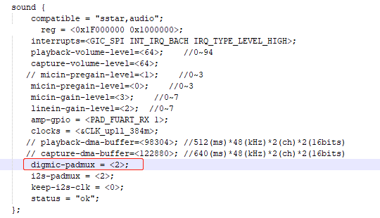
1.4.1. Configure pin to dmic mode
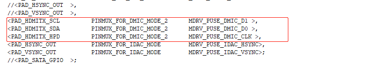
Before using dmic, you need to confirm with the hardware which set of pins to use, and then configure the digmic-padmux to the corresponding Mode in the infinity2m.dtsi and padmux files. For example, the public version uses PAD_HDMITX_SCL (D1) & PAD_HDMITX_SDA (D0) & PAD_HDMITX_HPD (CLK)
As follows, find the corresponding *.dtsi file and find the sound node configuration:
At the same time, find the corresponding *padmux.dtsi file and configure the corresponding padmux mode
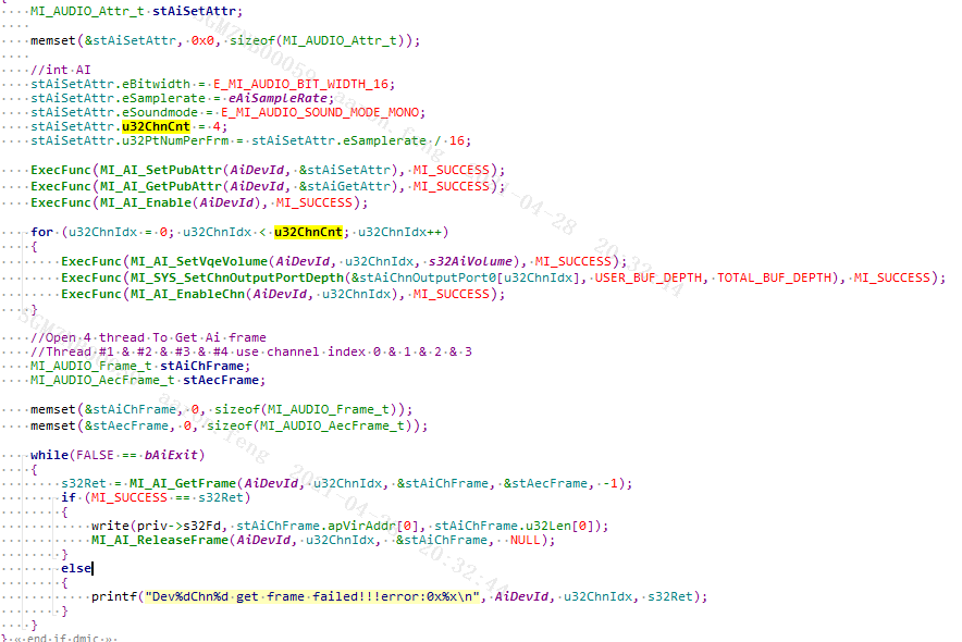
1.4.2. 4 dmic usage scenarios
When Dmic is in use, regardless of whether 2dmic or 4dmic is used, the device ID used is AI_DEV_ID_DMIC (1), and ChannelCount is used to determine how many channels of audio need to be collected.
The reference demo is used as follows:
1.5. I2s RX usage scenarios
1.5.1. I2s rx pin configuration
Before using i2s rx, you need to confirm with the hardware which group of pins you are using, and then configure the corresponding Mode in the corresponding padmux. For example, if the public version uses the PAD_SD_D0 & PAD_SD_CLK & PAD_SD_CMD && PAD_SD_D3 group of modes, the corresponding configuration as follows:
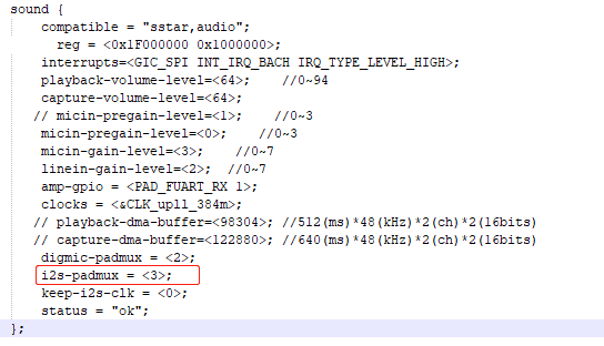
Find the sound node in the corresponding dtsi file:
Find the corresponding *padmux.dtsi file and configure the following padmux :
<PAD_SD_D0 PINMUX_FOR_I2S_MODE_3 MDRV_PUSE_I2S_WCK>,

<PAD_SD_CLK PINMUX_FOR_I2S_MODE_3 MDRV_PUSE_I2S_BCK>,

<PAD_SD_CMD PINMUX_FOR_I2S_MODE_3 MDRV_PUSE_I2S_SDI>,

<PAD_SD_D3 PINMUX_FOR_I2S_MODE_3 MDRV_PUSE_I2S_SDO>,
Please refer to HW CheckList of hardware documentation for the correspondence between pins and modes used.
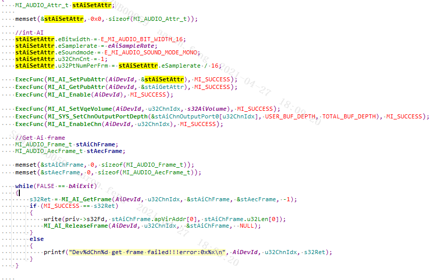
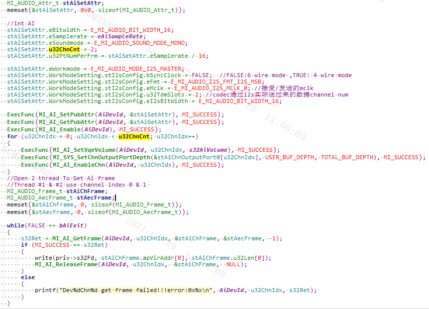
1.5.2. Common two-way i2s usage scenarios
The Demo reference for the use of ordinary two-way i2s rx is as follows:
1.6. Usage scenarios of Line In
The usage of Line in is the same as amic , but the way of setting Gain is different. For details, please refer to the documentation of MI AI API.
2. AO (audio output) usage scene reference
2.1. Output interface types supported by AO
| Interface Type | Maximum Channel | Sample Rate | Sample Depth | Channel |
|---|---|---|---|---|
| Line out | 2 | 8/11.025/12/16/22.05/32/44.1/48KHz | 16bit | STEREO/MONO |
| I2s | 2 | 8/16/32/48 KHz (mclk not supported) | 16bit | STEREO/MONO |
2.2. Device ID supported by AO
| Device ID | Interface Type |
|---|---|
| AO_DEV_ID_LINE_OUT (0) | Two-way Lineout |
| AO_DEV_ID_I2S_TX (1) | I2s |
| AO_DEV_ID_HDMI (2) | HDMI (only supported by SSD203) |
| AO_DEV_ID_HDMI_AND_LINEOUT (3) | HDMI + LINE OUT (only supported by SSD203) |
2.3. Lineout usage scenarios
2.3.1. Lineout Amp configuration instructions
SSD20X supports two-way Line out left and right channel output, but does not support single-channel attribute control operation (such as does not support separate volume adjustment)
According to the hardware layout, amp_gpio can be configured as follows
-
Open kernel\arch\arm\boot dts \infinity2m.dtsi and modify the sound device tree node amp-gpio
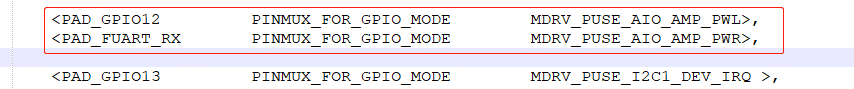
As shown in the figure below, set PAD_GPIO12/PAD_FUART_RX as the left and right channel control pins of amp_gpio

-
Open kernel\arch\arm\boot\dts\pioneer3-ssc020a-s01a-demo-camera-padmux.dtsi (open *_padmux.dtsi used by config according to the actual situation )
As shown in the figure below, set PAD_SR_IO15/PAD_SR_IO16 to MDRV_PUSE_AIO_AMP_PWL/MDRV_PUSE_AIO_AMP_PWR respectively
2.3.2. All the way lineout usage scenarios
Use Lineout to support left and right channels, but only one channel of dev is supported. If you need to play stereo left and right channels, you need to combine the left and right channels of the audio file itself to play through STEREO MODE (does not support feeding data separately)
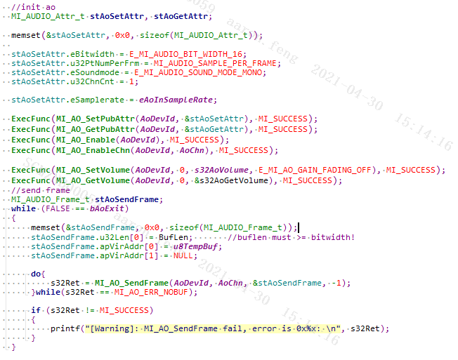
The reference to use Demo is as follows:
2.4. I2s Tx usage scenarios
2.4.1. I2s Tx pin configuration
Before using i2s rx, you need to confirm with the hardware which group of pins you are using, and then configure the corresponding Mode in the corresponding padmux. For example, if the public version uses the PAD_SD_D0 & PAD_SD_CLK & PAD_SD_CMD && PAD_SD_D3 group of modes, the corresponding configuration is as follows:

Find the corresponding *padmux.dtsi file and configure the following padmux:
<PAD_SD_D0 PINMUX_FOR_I2S_MODE_3 MDRV_PUSE_I2S_WCK>,

<PAD_SD_CLK PINMUX_FOR_I2S_MODE_3 MDRV_PUSE_I2S_BCK>,

<PAD_SD_CMD PINMUX_FOR_I2S_MODE_3 MDRV_PUSE_I2S_SDI>,

<PAD_SD_D3 PINMUX_FOR_I2S_MODE_3 MDRV_PUSE_I2S_SDO>,
Please refer to HW CheckList of hardware documentation for the correspondence between pins and modes used .
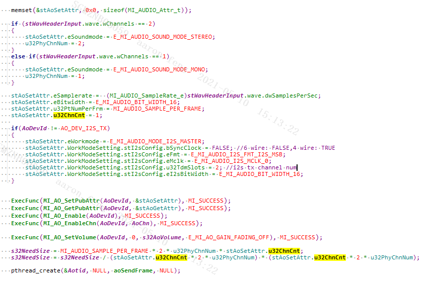
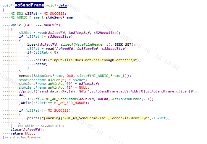
2.4.2. Common two-way i2s tx usage scenarios
The reference usage Demo is as follows: