SSD_Audio_ALSA开发指南
REVISION HISTORY
| Revision No. | Description |
Date |
|---|---|---|
| 1.0 | 03/29/2023 |
前言
本章主要描述Audio的相关概念、代码结构。
1. 概述
1.1. 概述
本章指导客户了解 sigmastar 平台 alsa 架构和使用方法,达到初步使用 alsa 和 定位音频问题的目的。
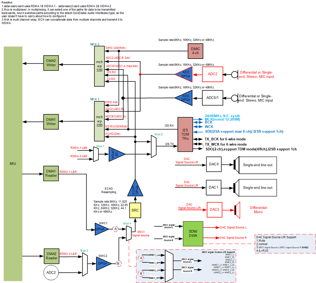
sigmastar 平台 alsa 架构遵从标准 alsa 架构,标准 alsa 解耦方案框图如下。在维持标准系统架构不变的前提下,将私有业务行为融合并同步于标准 asla 系统中,主要涉及 2 个方面,音量控制方案&外设通路播放。
遵从标准 alsa-lib 实现解耦,也是解耦方案的核心所在。向上提供接口供用户层 application (如 alsa-utils 或者 参考示例 prog_alsa_demo)调用,向下调用 alsa 标准接口实现音量、设备切换等功能。涉及主要方案如下:
| Application   |       alsa-utils       |  |      tinyalsa            |
|               | aplay  arecord  amixer |  | tinyplay tinycap tinymix |
|----------------------------------------------------------------------|
| User Space    |       alsa-lib         |  |      tinyalsa-lib        |
|----------------------------------------------------------------------|
| Kernel Space  |               alsa Core & asoc core                  |
|----------------------------------------------------------------------|
| Device driver |                    sound driver                      |
|----------------------------------------------------------------------|
|                                      Hardware                        |
1.2. 概念
| 名称 | 描述 |
|---|---|
| DAI | Diaital Audio Interfaces 数字音频接口 |
| CPU DAI | 主控端的 Audio Data Interface,比如 I2S,Pdm,Tdm |
| CODEC DAI | 即 Codec |
| DAI_LINK | 绑定 Cpu_Dai 和 Codec_Dai 为一个声卡,等同于 Machine Driver |
| DMAENGINE | 用于 Cpu 和 I2S 等 Dai 之间的 Dma 传输引擎,实际是通过 Dma 来进行数据的搬运 |
| DAPM | 动态音频电源管理,用于动态管理 Codec 等的电源管理,根据通路的开启配置开关,以达到保证功能的前提下功耗尽量小 |
| JACK | 耳机的接口检测,大部分使用 Codec 自身的检测机制,小部分使用 IO 来进行模拟 |
1.3. Audio ALSA 框架和Audio音频拓扑图
1.4. 代码结构
| 项目 | 功能 | 路径 |
|---|---|---|
| Sound soc | 主要包含公共部分代码,包括 dapm 控制, jack,dmaengine, core 等等 | sound/soc/ |
| Sigmastar platform | Simastar 平台的 cpu dai 的驱动以及自定义声卡 machine driver | sound/soc/sstar |
| Codec driver | 所有的 codec driver 存放位置 | sound/soc/codecs |
2. Audio 开发指南
本章描述如何添加声卡,调试声卡。一个声卡包含 cpu_dai, codec_dai, 以及 dai_link 组成,分别对应 cpu dai 的 dirver,比如 bach driver, bach2 driver;codec driver;dai_link driver,也就 是 machine driver, 比如 sound/soc/sstar/pioneer5/sstar_asoc_card.c。
2.1. 关键字说明
-
DMA
DMA 即 direct memory access 直接存储器访问,DMA 传输将数据从一个地址空间复制到另一个地址空间,提供在外设和存储器之间或者存储器和存储器之间的高速数据传输。当 CPU 初始化这个传输动作,传输动作本身是由 DMA 控制器来实现和完成的。DMA 传输方式无需 CPU 直接控制传输,也没有中断处理方式那样保留现场和恢复现场过程,通过硬件为 RAM 和 IO 设备开辟一条直接传输数据的通道,使得 CPU 的效率大大提高。
-
WDMA
WDMA 即 direct memory access writer 直接存储器访问写入器。
-
RDMA
RDMA 即 direct memory access reader 直接存储器访问读取器。
-
MUX
MUX 即 multiplexer 数据选择器,在多路数据传送中,能够根据需要将其中任意多路选出来的电路。WDMA 前面的 Mux 为 WDMA 选择多个数据源,可支持选择 ½/4 个数据源(数据源可以相同也可以不同),每个数据源各有 2 声道,即选择 2/4/8 个声道的数据由 WDMA 写道 DRAM,起到多路开关的作用。而接近输出外设接口(I2S_TX/HDMI/DAC 等)的 Mux 实现的是多选一的作用。
-
DPGA
DPGA 即 digital programmable gain amplifier 数字可编程增益放大器,是一种通用性很强的放大器,其放大倍数可以根据需要用程序进行控制。
-
DMIC
DMIC 即 digital microphone interface 数字麦克风接口,audio codec 仅仅提供 DMIC 接口,并非完整的 DMIC。DMIC 接口提供 DMIC 工作所需要的时钟信号,接收从 DMIC 来的 PDM 信号。
-
ADC
ADC 即 analog digital conversion 模拟数字转换,将模拟信号转换为数据信号的电子元件。
-
I2S
I2S 即 inter-IC sound 集成电路内置音频总线,是飞利浦公司为数字音频设备之间的音频数据传输而制定的一种总线标准。Sigmastar 的 I2S 总线仅支持标准 I2S 数据格式以及左对齐的 I2S 数据格式。同时也支持 TDM(Time-Division Multiplexing)时分复用技术,将不同的信号相互交织在不同的时间段内,沿着同一个信道传输,可同时支持 ½/4/8 通道数据传输。
-
DAC
DAC 即 digital analog conversion 数字模拟转换,将数字信号转换为模拟信号的电子元件。
-
SRC
SRC 即 sample rate convert 采样率转换,对语音数字信号进行采样率转换。
-
HDMI
HDMI(high definition multimedia interface, 高清多媒体接口),audio output 输出接口,是一种全数字化视频和音频发送接口,可以发送未压缩的音频及视频信号。
-
Mixer
Mixer 即混音,使用线性叠加平均的算法(如果某一路音频的音量特别小,整个混音结果音量会被拉低),混音后可以设置输出的采样率。
-
device(音频输入/输出设备)
audio output 的 device 指的是 audio codec 的 RDMA。device 是 ASOC 对 audio codec 中 DMA 的抽象,1个card 下只挂载 1 个device,audio codec 中的 RDMA 和 output device 为 一一对应的关系。如 card 0、device 0 对应 audio codec 中的 RDMA0,card 1、device 0 对应于audio codec 中的 RDMA1,以此类推。WDMA 和 input device 也是一一对应的关系。如 card 0、device 0 对应 audio codec 中的 WDMA0,card 1、device 0 对应于audio codec 中的 WDMA1。ASOC 的数据流均以 DMA 为中心进行串接。
ASOC 中还包括另一类 device,即 input 设备不经过 DMA,直接将数据流送至 output 设备,例如(AMIC -> DAC)。这一类 device 称为直通通路 device,即 passthrough ,目前仅 AI_MCH_VIR_SEL/AO_VIR_MUX_SEL 节点支持。
-
interface(音频输出外设)
output 的 interface 指的是 audio codec 的音频输出外设接口的抽象,如 DAC/I2S_TX 等接口。
input 的 interface 指的是 audio codec 的音频输入外设接口的抽象,如 AMIC/DMIC/I2S_RX 等接口。
-
output attach
output 的 attach 指的是将 interface 挂载到 RDMA 上,对于 output device 而言,attach 是将 RDMA 的输出信号连接到具体的 interface,使外设输出音频信号。output 支持动态 attach。
硬件混音:即当同一个 output interface 被 attach 到 2 个 output device 时候,output interface 的输出为 2 个 output device 输出混音后的结果。
直通通路:当使用场景中包含 passthrough 时候,需要先 attach input,再 attach output,否则将不能正常使用。
分发:即当多个 output interface 被 attach 到 1 个 output device 时候,从 RDMA 输出的信号经过 DPGA 做增益调节后,分成多个支路分别到达各个 interface,各个外设同时输出声音。
-
input attach
input 的 attach 指的是将 interface 挂载到 WDMA 对应的 MUX 上,即将 device 和 interface 关联起来。对于 input device 而言,attach 是设定 WDMA 对应的MUX,选择哪些 interface 的数据可以通过 MUX ,由 WDMA 做后续的数据搬移。input 不支持动态 attach。
-
detach
detach 指的是 将 interface 和 RDMA/WDMA 的连接断开。
-
output echo
output 的 echo 指的是 AEC 的回采参考数据。由 ALSA 框图可以看出,SRC 的输入是 RDMA 输出并经过 DPGA 放大的信号,SRC 的输出则是对输入进行重采样后的信号,可通过 multi channel 送进 WDMA,作为 AEC 算法的回声参考数据。
-
input echo
input 的 echo 指的是 audio codec 提供的 AEC 参考数据。对于 input device 而言,echo 表示 ALSA 框图中 SRC 的 输出信号。而对于 output device 而言,echo 表示将 output device 的输出连接到 SRC 的输入。下图以简单框图表示 input device 和 output device 同时使用 echo 的 数据流情况,应用即可获取到已经对齐的 AEC far end 和 near end 的数据。
_________ ___| ADC | <- AMIC _____ ________ _______ | ————————— | APP | <- | WDMA 0 | <- | MCH | <--| ————— ———————— ——————— | ________ |___ | SRC | ———————— ^ |\ | _____ ________ | \ | _____ | APP | -> | RDMA 0 | -> |DPGA------------------> | DAC | -> Speaker ————— ———————— | / ————— |/ -
GAIN
AI的Gain在ALSA架构上分成两类,一类是与Device相关联的DPGA Gain,即ALSA框图中的DPGA,另一类则是Interface所独有的Gain,目前拥有Gain的Interface有ADC以及Dmic接口。对于AI而言,若Interface本身没有独立的Interface Gain且也不与Dpga相连,则没法做Gain的设定。对AO而言,目前仅能通过Dpga调整Gain
DPGA即Digital Programmable Gain Amplifier数字可编程增益放大器,是一种通用性很强的放大器,其放大倍数可以根据需要用程序进行控制。
-
format
即表示用什么数据形式来表示一个音频采样样本,目前仅支持 S16_LE 格式(PCM linear 16 bit little endian)
-
sample rate
对于 input 表示 录音设备在单位时间内对模拟信号采样的次数,采样频率越高,机械波的波形越真实越自然。
对于 output 表示播放采样率。
-
period size
对于 output,period size 表示默认的起播条件(缓存中的样本数大于period size,才会起播)
-
I2S Mode
决定了 I2S 的工作模式,是标准的 I2S 模式还是 TDM I2S 模式(2 channel 或 多 channel),是 Master 还是 Slave (Master 提供同步时钟,Slave 接收同步时钟)。一般来说,工作模式没有什么限制,能与外接的 codec 时钟匹配上即可。
-
I2S BitWidth
收发数据的位宽,目前仅支持 16bit,硬件只能处理 16 bit。
-
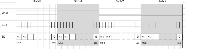
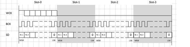
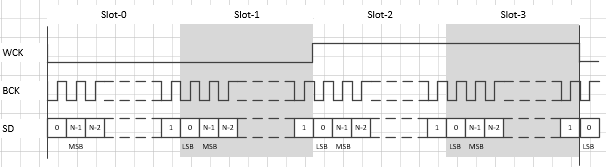
I2S format
即 I2S 的对齐方式,目前仅支持 I2S Philips 以及 Left-justified 对齐。
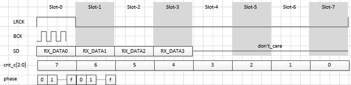
I2S Philips 的对齐格式,样本数据的第一个数据位出现在 WCLK(左右通道切换时钟)跳变的第一个 BCLK(串行时钟)后。
Left-justified 对齐格式,样本数据的第一个数据位出现在 WCLK(左右通道切换时钟)跳变的第一个 BCLK(串行时钟)内,且 WCLK 的极性与 I2S Philips 的对齐格式相反
-
MCLK
称为主时钟,也叫系统时钟(system clock),一般是采样频率的 256 或 384 倍,作用是为了使系统间能够更好的同步,并不是必须的。目前支持 11.2896M、12.288M、16.384M、19.2M、24M、48M 等。
-
4-wire/6-wire Mode
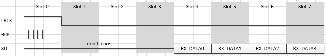
Sigmastar 的 I2S 有 2 种接线方式。
一种是 4-wire 模式,包括 RX_WCK、RX_BCK、RX_SDI、TX_SDO 四根线,此模式下,TX 没有独立的 clock,所有的 clock 均有 RX 提供,故在此模式下 TX 需要依赖 RX 来使用,没法单独使用 TX,且 I2S TX 的参数需要与 I2S RX 一致。
另一种是 6-wire 模式,包括 RX_WCK、RX_BCK、RX_SDI、TX_WCK、TX_BCK、TX_SDO 六根线,此模式下 RX 和 TX 各自独立,没有关联。
4-wire/6-wire Mode 的选择需要根据具体场景来决定。属于同一组 I2S 的 RX/TX 不能一边设置成 4-wire Mode,另一边设置成 6-wire Mode。
-
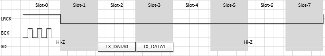
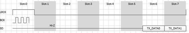
slot
表示 I2S 传输的声道数,目前 I2S 模式下支持 2 slot,TDM 模式下支持 4/8/16 slot,但是 I2S TX 的有效数据为 2 slot,当对 I2S TX 设置大于 2 的 slot 个数时候,除了 slot 0 和 slot 1,其他的均为无效数据。
-
passthrough (直通通道)
passthrough 意思指 input 设备直接将数据流送至 output 设备,不经过 DMA,以 ADC -> DAC 为例,
/| _ ________ ------- <- DPGA - | <- | ADC | <- AMIC | \| ————————— | | V |\ _______ ---> | - DPGA ->| | |/ | | _____ | Mixer | -> | DAC | -> Speaker _____ ________ |\ | | ————— | MIU | -> | RDMA 0 | -> - DPGA -> | | ————— ———————— |/ ———————d -
input 的 attach 节点
AI_MCH_01_SEL:即 MUX 的 0/1 声道
-
output 的 attach 节点
DMA 是给非硬件混音使用,DMA+SRC 是给硬件混音使用
2.2. simple-card
Simple card即简单通用的machine driver, 如果simple-card框架足够满足需求,建议优先使用simple card框架,简单,方便,且易用。
-
menuconfig 中打开 ASoC Simple sound card
打开simple-card,则自定义machine-driver不生效。
make menuconfig Device Drivers ---> <*> Sound card support ---> <*> Advanced Linux Sound Architecture ---> <*> ALSA for SoC audio support ---> <*> ASoC support for SigmaStar <*> ASoC Simple sound card support -
产品的DTS中添加Simple Card Node
asoc_sound_simple { status = "ok"; compatible = "simple-audio-card"; simple-audio-card,format = "i2s"; simple-audio-card,name = "sigmastar,asoc-card"; simple-audio-card,mclk-fs = <256>; simple-audio-card,cpu { sound-dai = <&bach1>; }; simple-audio-card,codec { sound-dai = <&dummy_codec1>; }; }; bach1: bach1 { status = "ok"; compatible = "sstar,bach"; sound-dma = <&dma1>; #sound-dai-cells = <0>; reg = <0x1F2A0400 0x800>; }; -
第三方codec对接参考 simple-card对接第三方codec-driver
2.3. 自定义的Machine Driver
-
当打开simple-card时,Machine Driver不生效.
menuconfig中关闭simple-card,使自定义machine-driver生效。
make menuconfig Device Drivers ---> <*> Sound card support ---> <*> Advanced Linux Sound Architecture ---> <*> ALSA for SoC audio support ---> <*> ASoC support for SigmaStar < > ASoC Simple sound card -
第三方codec对接参考 自定义machine-driver对接第三方codec-driver
2.4. 对接第三方Codec Driver
2.4.1. 自定义Machine Driver对接第三方Codec Driver
-
添加codec driver,比如添加:sound/soc/codec/es8328.c,如果不需要使用I2S的接口的话,可以默认不添加,默认使用sstar_dummy_codec.c。
-
修改sound/soc/codec/Kconfig以及Makefile加入驱动编译。
sound/soc/codec/Kconfig: config SND_SOC_ES8388 tristate "Everest Semi ES8388 CODEC" select SND_SOC_ES8388 sound/soc/codec/Makefile: snd-soc-es8388-objs := es8388.o obj-$(CONFIG_SND_SOC_ES8388)+= snd-soc-es8388.o -
menuconfig 中 enable card 以及 codec
关闭simple-card,使自定义machine-driver生效。
make menuconfig Device Drivers ---> <*> Sound card support ---> <*> Advanced Linux Sound Architecture ---> <*> ALSA for SoC audio support ---> <*> ASoC support for SigmaStar < > ASoC Simple sound card CODEC drivers ---> <*> SSTAR DUMMY AUX CODEC driver <*> Everest Semi ES8388 CODEC -
在产品的DTS中添加Card Note,根据需要修改DTSI中的设定,如果使用I2S的接口,需要在DTS中设定I2S的相关格式,相关格式的设定规则请参照Sigmastar_Linux_User_Guide_Audio的文档。
soc { sound { // I2S RX0 TDM i2s-rx0-tdm-mode = <2>; // 1:master 2:slave i2s-rx0-tdm-fmt = <1>; // 1:i2s justify 2:left justify i2s-rx0-tdm-wiremode = <2>; // 1:4wire 2:6 wire i2s-rx0-channel = <4>; i2s-rx0-tdm-ws-pgm = <0>; // 0: OFF 1: ON i2s-rx0-tdm-ws-width = <0>; // value: 0~31 (width = value + 1) i2s-rx0-tdm-ws-inv = <0>; // 0: normal 1: inverse WCK i2s-rx0-tdm-bck-inv = <0>; // 0: normal 1: inverse BCK i2s-rx0-tdm-ch-swap = <0 0 0>; // 0: OFF 1: ON // I2S TX0 TDM i2s-tx0-tdm-mode = <1>; // 1:master 2:slave i2s-tx0-tdm-fmt = <1>; // 1:i2s justify 2:left justify i2s-tx0-tdm-wiremode = <2>; // 1:4wire 2:6 wire i2s-tx0-channel = <4>; i2s-tx0-tdm-ws-pgm = <0>; // 0: OFF 1: ON i2s-tx0-tdm-ws-width = <0>; // value: 0~31 (width = value + 1) i2s-tx0-tdm-ws-inv = <0>; // 0: normal 1: inverse WCK i2s-tx0-tdm-bck-inv = <0>; // 0: normal 1: inverse BCK i2s-tx0-tdm-ch-swap = <0 0 0>; // 0: OFF 1: ON i2s-tx0-tdm-active-slot = <0xFF>; // value: 0x00 ~ 0xFF (bit0->slot0, bit1->slot1, ... ) status = "ok"; }; asoc_sound { compatible = "sstar, asoc-card"; sstar-audio-card,name = "sigmastar,asoc-card"; sstar-audio-card,cpu { sound-dai = <&bach1>; }; sstar-audio-card,codec { sound-dai = <&dummy_codec1>, <&es8388>; }; }; bach1: bach1 { status = "ok"; compatible = "sstar,bach"; sound-dma = <&dma1>; #sound-dai-cells = <0>; reg = <0x1F2A0400 0x800>; mclk-freq = <12288000>; }; i2c0{ status = "ok"; es8388:es8388@10{ status = "ok"; #sound-dai-cells = <0>; interrupts = <GIC_SPI INT_FIQ_DUMMY_31 IRQ_TYPE_LEVEL_HIGH>; compatible = "everest,es8388"; codec-name = "ES8388 HiFi"; clocks = <&CLK_mck_12p288m>; clock-names = "mclk"; reg = <0x10>; }; }; }; -
在machine driver(sstar_asoc_card.c)中添加对应的codec关联
static int sstar_asoc_card_probe(struct platform_device *pdev)
{
    if (np_codec_0)
    {
        card                                 = &sstar_asoc_card;
        card->dai_link[0].codecs->of_node    = np_codec_0;
        card->dai_link[0].codecs->dai_name   = "sstar-dummy-codec";
        card->dai_link[0].cpus->of_node      = np_cpu_d0;
        card->dai_link[0].platforms->of_node = np_cpu_d0;
        card->dai_link[1].codecs->of_node = np_codec_1;
        card->dai_link[1].codecs->dai_name = "ES8388 HiFi";
        card->dai_link[1].cpus->of_node = np_cpu_d0;
        card->dai_link[1].platforms->of_node = np_cpu_d0;
    }

static struct snd_soc_dai_link sstar_asoc_card_dailinks[] = {
    [0] = {
        .name        = "HiFi",
        .stream_name = "HiFi PCM",
        .init        = sstar_init,
        .ops         = &sstar_mc_ops,
        .dai_fmt     = SND_SOC_DAIFMT_I2S | SND_SOC_DAIFMT_NB_NF |
            SND_SOC_DAIFMT_CBS_CFS,
        SND_SOC_DAILINK_REG(private),
    },
    [1] = {
        .name = "aux-snd",
        .stream_name = "aux-snd-control",
        .init = sstar_init,
        .ops = &sstar_mc_ops,
        .dai_fmt = SND_SOC_DAIFMT_I2S | SND_SOC_DAIFMT_NB_NF |
            SND_SOC_DAIFMT_CBS_CFS,
        SND_SOC_DAILINK_REG(auxiliary),
    }
};
2.4.2. simple-card对接第三方Codec Driver
-
添加codec driver,比如添加:sound/soc/codec/es8388.c,
修改sound/soc/codec/Kconfig以及Makefile加入驱动编译。
sound/soc/codec/Kconfig: config SND_SOC_ES8388 tristate "Everest Semi ES8388 CODEC" sound/soc/codec/Makefile: snd-soc-es8388-objs := es8388.o obj-$(CONFIG_SND_SOC_ES8388)+= snd-soc-es8388.o -
menuconfig 中打开 ASoC Simple sound card 以及 codec。
打开simple-card,则自定义machine-driver不生效。
make menuconfig Device Drivers ---> <*> Sound card support ---> <*> Advanced Linux Sound Architecture ---> <*> ALSA for SoC audio support ---> <*> ASoC support for SigmaStar <*> ASoC Simple sound card support CODEC drivers ---> <*> SSTAR DUMMY AUX CODEC driver <*> Everest Semi ES8388 CODEC -
产品的DTS中添加Simple Card Node
asoc_sound_simple {
    status = "ok";
    compatible = "simple-audio-card";
    simple-audio-card,format = "i2s";
    simple-audio-card,name = "sigmastar,asoc-card";
    simple-audio-card,mclk-fs = <256>;
    simple-audio-card,cpu {
        sound-dai = <&bach1>;
    };
    simple-audio-card,codec {
        sound-dai = <&es8388>;
    };
};
bach1: bach1 {
    status = "ok";
    compatible = "sstar,bach";
    sound-dma = <&dma1>;
#sound-dai-cells = <0>;
    reg = <0x1F2A0400 0x800>;
    mclk-freq = <12288000>;
};
i2c0{
    status = "ok";
    es8388:es8388@10{
    status = "ok";
#sound-dai-cells = <0>;
    interrupts = <GIC_SPI  INT_FIQ_DUMMY_31 IRQ_TYPE_LEVEL_HIGH>;
    compatible = "everest,es8388";
    codec-name = "ES8388 HiFi";
    clocks = <&CLK_mck_12p288m>;
    clock-names = "mclk";
    reg = <0x10>;
    };
};
3. 声卡控制
3.1. 音量控制
-
所有通路使用 mixer control 接口完成音量调整。
-
音量作用在 interface 相连接的 DPGA 上
Playback:
________     _________     |\              _______
|  MIU | -> | RDMA 0  | -> |  - DPGA  ->  |  DAC  | -> Speaker
————————     —————————     |/              ———————

Capture:
________     _________      _______            /|     _____
|  MIU | <- | WDMA 0  | <- |  MUX  | <- DPGA -  | <- | ADC | <- AMIC
————————     —————————      ———————            \|     —————
-
调整 DPGA gain
支持音量调节的 control 节点
console:/ # tinymix -D 0 contents  or    tinymix -D 1 contents
Number of controls: 30
ctl    type    num    name                                value
0    INT    1    MMC1_L DPGA Volume                      127 (range 0->195)
1    INT    1    MMC1_R DPGA Volume                      127 (range 0->195)
2    INT    1    MMC2_L DPGA Volume                      127 (range 0->195)
3    INT    1    MMC2_R DPGA Volume                      127 (range 0->195)
4    INT    1    ECHO_L DPGA Volume                      127 (range 0->195)
5    INT    1    ECHO_R DPGA Volume                      127 (range 0->195)
6    INT    1    TDM0_L DPGA Volume                      127 (range 0->195)
7    INT    1    TDM0_R DPGA Volume                      127 (range 0->195)
8    INT    1    ADC01_L DPGA Volume                     127 (range 0->195)
9    INT    1    ADC01_R DPGA Volume                     127 (range 0->195)
10   INT    1    ADC23_L DPGA Volume                     127 (range 0->195)
11   INT    1    ADC23_R DPGA Volume                     127 (range 0->195)
调节范围:
区间(0-195),最小值为-63.5db, 最大值为34db, 步长为0.5db。
默认值为127,代表的增益为0db。
设为0即为静音。
调节方法:
MMC1_L DPGA Volume 的 dpga gain 设置为 200
console:/ # tinymix -D 0 set 0 200
MMC1_R DPGA Volume 的 dpga gain 设置为 200
console:/ # tinymix -D 0 set 1 200
MMC2_L DPGA Volume 的 dpga gain 设置为 200
console:/ # tinymix -D 0 set 2 200
MMC2_R DPGA Volume 的 dpga gain 设置为 200
console:/ # tinymix -D 0 set 3 200

alsa-utils 使用参考:
console:/ # ./amixer cset name='MMC1_L DPGA Volume' 200
console:/ # ./amixer cset name='MMC2_L DPGA Volume' 200

设置前:
console:/ # tinymix -D 0 contents
Number of controls: 30
ctl   type  num  name                                value
0     INT   1    MMC1_L DPGA Volume                  127 (range 0->195)
1        INT   1    MMC1_R DPGA Volume                  127 (range 0->195)
设置后:
console:/ # tinymix -D 0 contents
Number of controls: 30
ctl   type  num  name                                value
0     INT   1    MMC1_L DPGA Volume                  200 (range 0->195)
1     INT   1    MMC1_R DPGA Volume                  200 (range 0->195)
-
调整 ANOLG Gain
支持音量调节的 control 节点
console:/ # tinymix -D 0 contents  or    tinymix -D 1 contents
Number of controls: 30
ctl   type  num  name                                value
12    INT   2       ADC01_ANOLG_GAIN                    2, 2 (range 0->21)
13      INT   2       ADC23_ANOLG_GAIN                    2, 2 (range 0->21)
调节范围:
两个值分别代表左声道和右声道
区间(0~21),最小值为-6db, 最大值为57db, 步长为3db.
默认值为2,代表的增益为0db。
调节方法:
ADC01_ANOLG_GAIN 的左右声道 gain 设置为 10
console:/ # tinymix -D 0 set 12 10 10

ADC23_ANOLG_GAIN 的左右声道 gain 设置为 10
console:/ # tinymix -D 0 set 13 10 10

alsa-utils 使用参考:
console:/ # ./amixer cset name='ADC01_ANOLG_GAIN' 10 10
console:/ # ./amixer cset name='ADC23_ANOLG_GAIN' 10 10

设置前:
console:/ # tinymix -D 0 contents
Number of controls: 30
ctl   type  num  name                                value
12    INT   2       ADC01_ANOLG_GAIN                    2, 2 (range 0->21)
13      INT   2       ADC23_ANOLG_GAIN                    2, 2 (range 0->21)
设置后:
console:/ # tinymix -D 0 contents
Number of controls: 30
ctl   type  num  name                                value
12    INT   2       ADC01_ANOLG_GAIN                    10, 10 (range 0->21)
13      INT   2       ADC23_ANOLG_GAIN                    10, 10 (range 0->21)
-
调整 DMIC Gain
支持音量调节的 control 节点
console:/ # tinymix -D 0 contents  or    tinymix -D 1 contents
Number of controls: 30
ctl   type  num  name                                value
14    INT   2       DMIC01_GAIN                         2, 2 (range 0->4)
15      INT   2       DMIC23_GAIN                         2, 2 (range 0->4)
调节范围:
两个值分别代表左声道和右声道
区间(0~4),最小值为0db, 最大值为24db, 步长为6db.
调节方法:
DMIC01_GAIN 的左右声道 gain 设置为 10
console:/ # tinymix -D 0 set 14 3 3

DMIC23_GAIN 的左右声道 gain 设置为 10
console:/ # tinymix -D 0 set 15 3 3

alsa-utils 使用参考:
console:/ # ./amixer cset name='DMIC01_GAIN' 3 3
console:/ # ./amixer cset name='DMIC23_GAIN' 3 3

设置前:
console:/ # tinymix -D 0 contents
Number of controls: 30
ctl   type  num  name                                value
14    INT   2       DMIC01_GAIN                         2, 2 (range 0->4)
15      INT   2       DMIC23_GAIN                         2, 2 (range 0->4)
设置后:
console:/ # tinymix -D 0 contents
Number of controls: 30
ctl   type  num  name                                value
14    INT   2       DMIC01_GAIN                         3, 3 (range 0->4)
15      INT   2       DMIC23_GAIN                         3, 3 (range 0->4)
3.2 设备树配置
-
主从模式
属性名称 描述 取值范围 i2s-rx-tdm-mode 配置主从模式 1:主模式
2:从模式i2s-tx-tdm-mode 配置主从模式 1:主模式
2:从模式 -
I2S格式
属性名称 描述 取值范围 i2s-rx-tdm-fmt 配置I2S格式 1:标准格式
2:左对齐格式i2s-tx-tdm-fmt 配置I2S格式 1:标准格式
2:左对齐格式标准格式:
I2S模式属于左对齐中的一种特例,也叫PHILIPS模式,是由标准左对齐格式再延迟一个时钟位变化来的。

左对齐格式:
和标准格式对比可以看出,标准左对齐格式的数据的MSB没有相对于BCLK延迟一个时钟。

-
I2S wiremode
属性名称 描述 取值范围 i2s-rx-tdm-wiremode 配置I2S接线模式 1:4线模式
2:6线模式i2s-tx-tdm-wiremode 配置I2S接线模式 1:4线模式
2:6线模式四线模式下:
外部codec提供时钟时,i2s-rx-tdm-mode和i2s-tx-tdm-mode均设为从模式.
外部codec不提供时钟时,i2s-rx-tdm-mode和i2s-tx-tdm-mode均设为主模式.
lookback时(TXRX对接),i2s-rx-tdm-mode和i2s-tx-tdm-mode均设为主模式.
-
I2S 通道数
属性名称 描述 取值范围 i2s-rx-channel 配置I2S 通道数 2、4、8 i2s-tx-channel 配置I2S 通道数 2、4、8 I2SA支持通道2、4、8 I2SB仅支持1通道,为PCM Mode.
-
I2S tdm配置
属性名称 描述 取值范围 i2s-rx-tdm-ws-pgm TDM可编程模式 0: OFF
1: ONi2s-tx-tdm-ws-pgm TDM可编程模式 0: OFF
1: ONi2s-rx-tdm-ws-width 配置tdm WCK的宽度 0~31 (width = value + 1) i2s-tx-tdm-ws-width 配置tdm WCK的宽度 0~31 (width = value + 1) 示例:
i2s-tx-tdm-ws-pgm = <0>;
i2s-tx-tdm-ws-width = <0>;
i2s-rx-tdm-ws-pgm = <1>;
i2s-rx-tdm-ws-width = <0xf>;
不打开pgm:width属性不生效,WCK占空比固定为50%
打开pgm:此时width属性生效,WCK宽度为(width+1)*bclk
-
I2S wck翻转
属性名称 描述 取值范围 i2s-rx-tdm-ws-inv I2S wck翻转 0: 不翻转
1: 翻转i2s-tx-tdm-ws-inv I2S wck翻转 0: 不翻转
1: 翻转不翻转:

翻转:
-
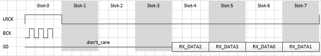
I2S rx-ch-swap
属性名称 描述 取值范围 i2s-rx-tdm-ch-swap 配置tx i2s通道交换 <0 0>
<0 1>
<1 0>
<1 1>示例:
i2s-tx-tdm-ch-swap = <0 0>;
<0 0>:
<0 1>:

<1 0>:
<1 1>:
-
I2S tx-ch-swap
属性名称 描述 取值范围 i2s-tx-tdm-ch-swap 配置tx i2s通道交换 <0 0>
<0 1>
<1 0>
<1 1><0 0>:

<0 1>:
<1 0>:

<1 1>:
-
I2S tx 有效通道
属性名称 描述 取值范围 i2s-tx-tdm-active-slot 配置I2S tx 有效通道 0x00 ~ 0xFF (bit0->slot0, bit1->slot1, ... ) -
高通滤波
属性名称 描述 取值范围 hpf-adc1-dmic2ch-level 高通滤波level < switch value >
switch:
0:not use this level
1:use this level
value: 0~9、0xfhpf-adc2-level 高通滤波level < switch value >
switch:
0:not use this level
1:use this level
value: 0~9、0xfhpf-dmic4ch-level 高通滤波level < switch value >
switch:
0:not use this level
1:use this level
value: 0~9、0xf示例:
hpf-adc1-dmic2ch-level = <1 0xf>;
hpf-adc2-level         = <1 0xf>;
hpf-dmic4ch-level      = <1 0x0>;
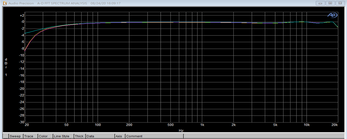
HPF关闭 截止频率30Hz:
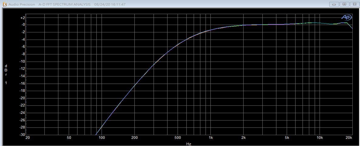
HPF 0x0 截止频率1400Hz:

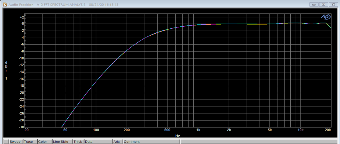
HPF 0x1 截止频率700Hz:
HPF 0x2 截止频率350Hz:
HPF 0x3 截止频率175Hz:
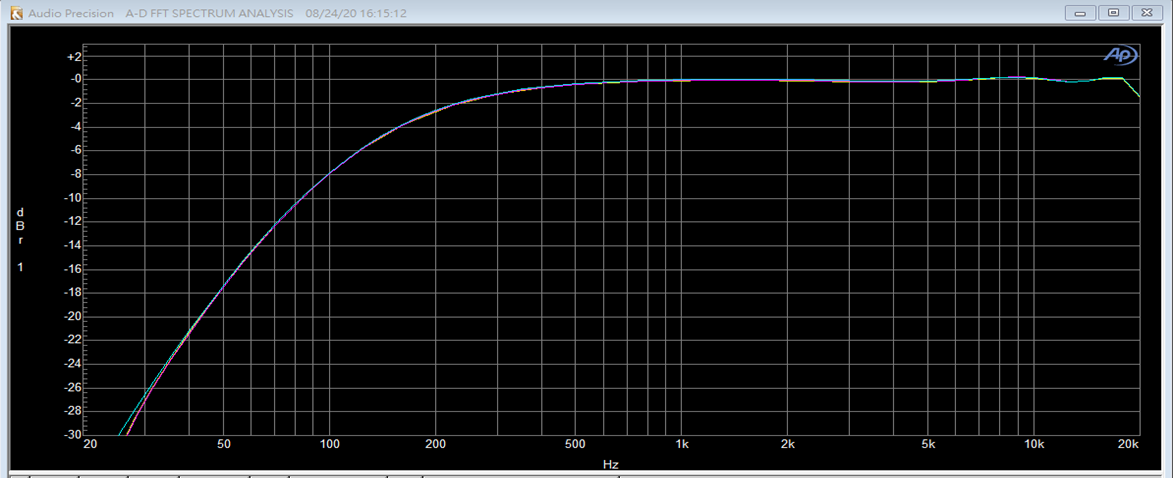
HPF 0x4 截止频率92.5Hz:

HPF 0x5 截止频率55Hz:

HPF 0x6 截止频率35Hz:

HPF 0x7 截止频率30Hz:

HPF 0x8 截止频率30Hz:
HPF 0x9 截止频率30Hz:
HPF 0xf 截止频率30Hz:
-
防止杂音、爆破音
属性名称 描述 取值范围 dac_anti_noisy_on 软件延迟300ms,防止启播/启录状态杂音 0:OFF
1:ONkeep_adc_power_on ADC电源常供电 0:OFF
1:ONkeep_dac_power_on DAC电源常供电 0:OFF
1:ON -
dmic bck mode
属性名称 描述 取值范围 dmic-bck-mode-8k 配置8K BCK 1~7 dmic-bck-mode-16k 配置16K BCK 8~14 dmic-bck-mode-32k 配置32K BCK 15 dmic-bck-mode-48k 配置48K BCK 16 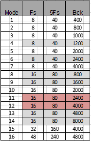
-
控制打印等级
属性名称 描述 取值范围 debug-level 控制打印等级 0x00000001 : debug fot test
0x00000002 : debug DMA status
0x00000004 : debug bach and hdmi rx frequency difference
0x00000008 : debug irq status
0x00000010 : debug audio delay status
0x00000020 : debug Indicates the creation status of a path
0x00000040 : debug hdmirx audio format report
0x00000080 : debug audio clk
0x00000100 : debug audio i2s动态调整参考调整debug level
3.3. 音频通路控制
系统提供 ADC、DMIC、ECHO_RX、I2S_RX、DAC、I2S_TX、ECHO_TX 的音频通路音频输入输出。
系统提供 aplay、arecord、amixer 原生 alsa 框架、compress 播放的音频输出,硬件混音支持。
————————————————————————————————————————————————————————————————————————————————————————————————————————————————
    interface(devide node)      |              CPU DAI                  |           DMA Engine
    -----------------------------------------------------------------------------------------------------
                                                DAC
                                                I2S_TX_A
                                                I2S_TX_B             <---       R_DMA_0_Playback
                                                ECHO_TX
                            /
        card_0 - device_0 -         ---------------------------------------------------------------------
                            \        AI_MCH_01_SEL        ADC_A
                                    AI_MCH_23_SEL        ADC_B
                                    AI_MCH_45_SEL        DMIC
                                    AI_MCH_67_SEL   ->   I2S_RX_A    --->       W_DMA_0_Capture
-              ------------------------------------------------------------------------------------------
\                                              DAC
                                                I2S_TX_A
                                                I2S_TX_B             <---       R_DMA_1_Playback
                                                ECHO_TX
                            /
        card_1 - device_0 -         ---------------------------------------------------------------------
                            \        AI_MCH_01_SEL        ADC_A
                                    AI_MCH_23_SEL        ADC_B
                                    AI_MCH_45_SEL        DMIC
                                    AI_MCH_67_SEL   ->   I2S_RX_A    --->       W_DMA_1_Capture
————————————————————————————————————————————————————————————————————————————————————————————————————————————————
声卡 0、1 支持的 control 节点,通路指 name 为 *_SEL 的节点
当前输入输出通路支持 playback、capture、passthrough、aec、compress、volume adjust、channel mode 等使用场景
console:/ # tinymix -D 0  contents
Number of controls: 50
ctl type   num name                                   value
... ...
18    ENUM     1    AI_MCH_01_SEL                           > AI_DETACH, ADC_A, ADC_B, DMIC_A_01, DMIC_A_23, ECHO_01, I2S_RXA_0_1, I2S_RXA_2_3, I2S_RXA_4_5, I2S_RXA_6_7, I2S_RXB_0_1,
19    ENUM     1    AI_MCH_23_SEL                           > AI_DETACH, ADC_A, ADC_B, DMIC_A_01, DMIC_A_23, ECHO_01, I2S_RXA_0_1, I2S_RXA_2_3, I2S_RXA_4_5, I2S_RXA_6_7, I2S_RXB_0_1,
20    ENUM     1    AI_MCH_45_SEL                           > AI_DETACH, ADC_A, ADC_B, DMIC_A_01, DMIC_A_23, ECHO_01, I2S_RXA_0_1, I2S_RXA_2_3, I2S_RXA_4_5, I2S_RXA_6_7, I2S_RXB_0_1,
21    ENUM     1    AI_MCH_67_SEL                           > AI_DETACH, ADC_A, ADC_B, DMIC_A_01, DMIC_A_23, ECHO_01, I2S_RXA_0_1, I2S_RXA_2_3, I2S_RXA_4_5, I2S_RXA_6_7, I2S_RXB_0_1,
22    ENUM     1    AI_MCH_VIR_SEL                          > AI_DETACH, ADC_A, ADC_B,
23    ENUM     1    AO_VIR_MUX_SEL                          > VIR_DETACH, DAC01, DAC23,
24    ENUM     1    DAC_A_SEL                               > AO_DETACH, DMA_L, DMA_R,
25    ENUM     1    DAC_B_SEL                               > AO_DETACH, DMA_L, DMA_R,
26    ENUM     1    DAC_C_SEL                               > AO_DETACH, DMA_L, DMA_R,
27    ENUM     1    ECHO_SEL                                > AO_DETACH, DMA,
28    ENUM     1    I2S_TXA_SEL                             > AO_DETACH, DMA,
29    ENUM     1    I2S_TXB_SEL                             > AO_DETACH, DMA,
-
音频输出设备策略
支持喇叭、I2S_TX 的设备输出。支持设备间的切换。
播放过程中,动态调整输出设备流程:
___________________      ______      __________
|  attach (speaker) | -> | open | -> | playback | -> (开始动态切换) ->
———————————————————      ——————      ——————————

___________      ________      _______      _________
|  detach   | -> | attach | -> | close | -> | detach  |
|  (speaker)|    | (i2s)|    |       |    | (i2s) |
———————————      ————————      ———————      —————————

(因为是 attach/detach 不同 interface, 所以切换过程中会存在断音)
静置状态下,调整外接设备流程:
__________ -> | playback | - ________ ______ / —————————— \ _______ ________ | attach | -> | open | -> | close | -> | detach | ———————— —————— \ __________ / ——————— ———————— -> | capture | - —————————— -
连接(attach)通路
-
单独或同时连接 DAC 输出
有三组独立的DAC:DAC_A_SEL、DAC_B_SEL、DAC_C_SEL,可以分别连接DMA左声道、右声道。 播放单声道的音频文件时,需要 attach 到 DMA_L 才有声音。
tinyalsa 使用参考:
console:/ # tinymix -D 0 set DAC_A_SEL DMA_L   // R_DMA_L attach 到 DAC_A
console:/ # tinymix -D 0 set DAC_B_SEL DMA_R   // R_DMA_R attach 到 DAC_B
console:/ # tinymix -D 0 set DAC_C_SEL DMA_R   // R_DMA_R attach 到 DAC_C
alsa-utils 使用参考:
console:/ # ./amixer cset name='DAC_A_SEL' 1
console:/ # ./amixer cset name='DAC_B_SEL' 2
console:/ # ./amixer cset name='DAC_C_SEL' 2
查看状态:
console:/ # tinymix -D 0 contents
... ...
24    ENUM    1    DAC_A_SEL                               AO_DETACH, > DMA_L, DMA_R,
25    ENUM    1    DAC_B_SEL                               AO_DETACH, DMA_L, > DMA_R
26    ENUM    1    DAC_C_SEL                               AO_DETACH, DMA_L, > DMA_R
... ...
-
单独或同时连接 AMIC + DMIC 输入
-
单声道 mono 的处理:
tinyalsa 使用参考:
multichannel 的 0、1 声道 attach 到 AMIC 的 0、1
console:/ # tinymix -D 0 set AI_MCH_01_SEL 1 ADC_A
alsa-utils 使用参考:
console:/ # ./amixer cset name='AI_MCH_01_SEL' ADC_A
注意:capture 取数据的时候,即 mono 默认取 multichannel 的 0 声道
-
多声道:AMIC + DMIC 同时输入 8 声道数据
例如:AMIC 数据存放在 0、1 声道,DMIC 数据存放在 2、3、4、5、6、7 声道
tinyalsa 使用参考:
console:/ # tinymix -D 0 set AI_MCH_01_SEL ADC_A   // multichannel 的 0、1 声道 attach 到 AMIC 的 0、1
console:/ # tinymix -D 0 set AI_MCH_23_SEL DMIC_A_01   // multichannel 的 2、3 声道 attach 到 DMIC 的 0、1
console:/ # tinymix -D 0 set AI_MCH_45_SEL DMIC_A_23   // multichannel 的 4、5 声道 attach 到 DMIC 的 2、3
console:/ # tinymix -D 0 set AI_MCH_67_SEL I2S_RXA_0_1   // multichannel 的 6、7 声道 attach 到 I2S_RXA的0、1
alsa-utils 使用参考:
console:/ # ./amixer cset name='AI_MCH_01_SEL' ADC_A
console:/ # ./amixer cset name='AI_MCH_23_SEL' DMIC_A_01
console:/ # ./amixer cset name='AI_MCH_45_SEL' DMIC_A_23
console:/ # ./amixer cset name='AI_MCH_67_SEL' I2S_RXA_0_1
查看状态:
console:/ # tinymix -D 0 contents
... ...
    18    ENUM    1    AI_MCH_01_SEL                           AI_DETACH, > ADC_A, ADC_B, DMIC_A_01, DMIC_A_23, ECHO_01, I2S_RXA_0_1, I2S_RXA_2_3, I2S_RXA_4_5, I2S_RXA_6_7, I2S_RXB_0_1,
    19    ENUM    1    AI_MCH_23_SEL                           AI_DETACH, ADC_A, ADC_B, > DMIC_A_01, DMIC_A_23, ECHO_01, I2S_RXA_0_1, I2S_RXA_2_3, I2S_RXA_4_5, I2S_RXA_6_7, I2S_RXB_0_1,
    20    ENUM    1    AI_MCH_45_SEL                           AI_DETACH, ADC_A, ADC_B, DMIC_A_01, > DMIC_A_23, ECHO_01, I2S_RXA_0_1, I2S_RXA_2_3, I2S_RXA_4_5, I2S_RXA_6_7, I2S_RXB_0_1,
    21    ENUM    1    AI_MCH_67_SEL                           AI_DETACH, ADC_A, ADC_B, DMIC_A_01, DMIC_A_23, ECHO_01, > I2S_RXA_0_1, I2S_RXA_2_3, I2S_RXA_4_5, I2S_RXA_6_7, I2S_RXB_0_1,
... ...
-
-
连接直通(passthrough)通路
例如:ADC 到 DAC 的直通
tinyalsa 使用参考:
console:/ # tinymix -D 0 set AI_MCH_VIR_SEL 1
console:/ # tinymix -D 0 set AO_VIR_MUX_SEL 1
alsa-utils 使用参考:
console:/ # ./amixer cset name='AI_MCH_VIR_SEL' 1
console:/ # ./amixer cset name='AO_VIR_MUX_SEL' 1
-
I2S 通路的连接
I2S_TX、I2S_RX 的 主从模式以及时钟信号等相关配置,请在 kernel 的 dtsi 文件中配置。
tinyalsa 使用参考:
console:/ # tinymix -D 0 set I2S_TXA_SEL 1
alsa-utils 使用参考:
console:/ # ./amixer cset name='I2S_TXA_SEL' 1
-
-
断开(detach)通路
断开通路的时候,只需要把对应通路切换到 DETACH 状态(AI_DETACH / AO_DETACH / VIR_DETACH)即可,例如:detach 通路 DAC
tinyalsa 使用参考:
console:/ # tinymix -D 0 set DAC_SEL 0
alsa-utils 使用参考:
console:/ # ./amixer cset name='DAC_SEL' 0
4. 常用调试方法
4.1. procfs
4.1.1. 确认声卡是否注册成功
/ # cat  /proc/asound/cards
    0 [sstarasoccard  ]: sstar-asoc-card - sstar-asoc-card
                        sstar-asoc-card
    1 [sstarasoc2card ]: sstar-asoc2-car - sstar-asoc2-card
                        sstar-asoc2-card
/ # ls /dev/snd/
controlC0  controlC1  pcmC0D0c   pcmC0D0p   pcmC1D0c   pcmC1D0p   timer
4.1.2. 确认I2S TDM状态
/ # cat /proc/audio/tdm
TDM Rx
pgm         = <0>
width       = <0>
Wck inv     = <0>
Bck inv     = <0>
Bck inv     = <0>
I2S Mode    = <0>
MSMode      = <0>
Format      = <0>
RxMck       = <0>
RxEnMck       = <0>
Rxch        = <0>
RxWireMode  = <0>
ch-swap     = <0 0>
TDM Tx
pgm         = <0>
width       = <0>
Wck inv     = <0>
Bck inv     = <0>
I2S Mode    = <0>
MSMode      = <0>
Format      = <0>
TxMck       = <0>
TxEnMck       = <0>
Txch        = <0>
TxWireMode  = <0>
ch-swap     = <0 0>
active slot = <0xff>
debug-level = <0xffff>
4.1.3. 确认RDMA状态
/ # cat /proc/audio/RDMA
------------------------
RDMA ID is 0
AttachedChNum is 0
SampleRate is 0
bIsAttached is 0
interface0 is 0
interface1 is 0
------------------------
------------------------
RDMA ID is 1
AttachedChNum is 0
SampleRate is 0
bIsAttached is 0
interface0 is 0
interface1 is 0
4.1.4. 确认WDMA状态
/ # cat /proc/audio/WDMA
------------------------
WDMA ID is 0
AttachedChNum is 0
SampleRate is 0
bIsAttached is 0
interface0 is 0
interface1 is 0
interface2 is 0
interface3 is 0
------------------------
------------------------
WDMA ID is 1
AttachedChNum is 0
SampleRate is 0
bIsAttached is 0
interface0 is 0
interface1 is 0
interface2 is 0
interface3 is 0
------------------------
------------------------
4.1.5. 启用sinegen状态
echo RDMA1 -e 1 -g 1 -f 1 > /proc/audio/sinegen
4.1.6. 调整debug level
echo rx -debug 0xffff > /proc/audio/tdm

debug level:
        0x00000001 : debug fot test
        0x00000002 : debug DMA status
        0x00000004 : debug bach and hdmi rx frequency difference
        0x00000008 : debug irq status
        0x00000010 : debug audio delay status
        0x00000020 : debug Indicates the creation status of a path
        0x00000040 : debug hdmirx audio format report
        0x00000080 : debug audio clk
        0x00000100 : debug audio i2s
4.2. Xrun debug
Xrun debug 一般用于 debug underrun 或者 overrun,出现此两者情况时内核会 打印 log 协助问题的定位分析。Menuconfig 中需要开启如下选项:
[*] Advanced Linux Sound Architecture --->
    [*] Debug
        [*] More verbose debug
        [*] Enable PCM ring buffer overrun/underrun debugging0
然后在对应声卡/proc/asound/card0/xrun 中写入相应的值,值如下:
#define XRUN_DEBUG_BASIC         (1<<0)
#define XRUN_DEBUG_STACK         (1<<1) /* dump also stack */
#define XRUN_DEBUG_JIFFIESCHECK  (1<<2) /* do jiffies check */
比如 echo 1 > xrun 或者 echo 3 > xrun 或者 echo 7 > xrun 开启所有 debug 信息检测。
XRUN 包含 playback 的 under_run 和 capture 的 over_run,当出现 XRUN 的时候,需要改变每次 read/write data 的大小,一般是加大即可。
例如:使用 buffer size 的方式 代替 period size 的方式读写,具体请参考 read/write 示例中的注释。(tinyplay 和 aplay 中默认是每次写 period size 大小)
注意:设置的 period size 大小要是采样率的整数倍
4.3. tiny-alsa
4.3.1. tinypcminfo
查询声卡支持的采样率、格式、声道数等信息。
Usage: ./tinypcminfo -D card -d device

PCM out:
      Access:    0x000009
   Format[0]:    0x000004
   Format[1]:    00000000
 Format Name:    S16_LE
   Subformat:    0x000001
        Rate:    min=8000Hz    max=48000Hz
    Channels:    min=1         max=2
 Sample bits:    min=16        max=16
 Period size:    min=8         max=262144
Period count:    min=2         max=40960

PCM in:
      Access:    0x000009
   Format[0]:    0x000004
   Format[1]:    00000000
 Format Name:    S16_LE
   Subformat:    0x000001
        Rate:    min=8000Hz    max=48000Hz
    Channels:    min=1         max=8
 Sample bits:    min=16        max=16
 Period size:    min=2         max=262144
Period count:    min=2         max=4096
4.3.2. tinyplay
Usage: tinyplay file.wav [-D card] [-d device] [-p period_size] [-n n_periods]
播放test 音频文件:
tinyplay test.wav -D 0 -d 0 -p 1024 -n 3
Playing sample: 2 ch, 48000 hz, 32 bit
4.3.3. tinycap
Usage: tinycap file.wav [-D card] [-d device] [-c channels] [-r rate] [-b bits] [-p period_size] [-n n_periods]
48k 采样率录制音频:
tinycap test.wav -D 0 -d 0 –c 2 –r 48000 –b 16 –p 1024 –n 3
4.3.4. tinymix
控制 codec 内部的通路开关, 音量控制等。效果等同于 amixer
tinymix
usage: tinymix [options] <command>
options:
    -h, --help               : prints this help message and exits
    -v, --version            : prints this version of tinymix and exits
    -D, --card NUMBER        : specifies the card number of the mixer

commands:
    get NAME|ID              : prints the values of a control
    set NAME|ID VALUE(S) ... : sets the value of a control
        VALUE(S): integers, percents, and relative values
            Integers: 0, 100, -100 ...
            Percents: 0%, 100% ...
            Relative values: 1+, 1-, 1%+, 2%+ ...
    controls                 : lists controls of the mixer
    contents                 : lists controls of the mixer and their contents
4.4. alsa-utils
4.4.1. aplay
Usage: aplay [OPTION]... [FILE]...
-h, --help help
--version print current version
-l, --list-devices list all soundcards and digital audio devices
-L, --list-pcms list device names
-D, --device=NAME select PCM by name
-q, --quiet quiet mode
-t, --file-type TYPE file type (voc, wav, raw or au)
-c, --channels=# channels
-f, --format=FORMAT sample format (case insensitive)
-r, --rate=# sample rate
-d, --duration=# interrupt after # seconds
-s, --samples=# interrupt after # samples per channel
-M, --mmap mmap stream
-N, --nonblock nonblocking mode
-F, --period-time=# distance between interrupts is # microseconds
-B, --buffer-time=# buffer duration is # microseconds
--period-size=# distance between interrupts is # frames
--buffer-size=# buffer duration is # frames
-A, --avail-min=# min available space for wakeup is # microseconds
-R, --start-delay=# delay for automatic PCM start is # microseconds
(relative to buffer size if <= 0)
-T, --stop-delay=# delay for automatic PCM stop is # microseconds from xrun
-v, --verbose show PCM structure and setup (accumulative)
-V, --vumeter=TYPE enable VU meter (TYPE: mono or stereo)
-I, --separate-channels one file for each channel
-i, --interactive allow interactive operation from stdin
-m, --chmap=ch1,ch2,.. Give the channel map to override or follow
--disable-resample disable automatic rate resample
--disable-channels disable automatic channel conversions
--disable-format disable automatic format conversions
--disable-softvol disable software volume control (softvol)
--test-position test ring buffer position
--test-coef=# test coefficient for ring buffer position (default 8)
expression for validation is: coef * (buffer_size / 2)
--test-nowait do not wait for ring buffer - eats whole CPU
--max-file-time=# start another output file when the old file has recorded
for this many seconds
--process-id-file write the process ID here
示例:
./aplay Demo_new.wav
4.4.2. arecord
Usage: arecord [OPTION]... [FILE]...
-h, --help help
--version print current version
-l, --list-devices list all soundcards and digital audio devices
-L, --list-pcms list device names
-D, --device=NAME select PCM by name
-q, --quiet quiet mode
-t, --file-type TYPE file type (voc, wav, raw or au)
-c, --channels=# channels
-f, --format=FORMAT sample format (case insensitive)
-r, --rate=# sample rate
-d, --duration=# interrupt after # seconds
-s, --samples=# interrupt after # samples per channel
-M, --mmap mmap stream
-N, --nonblock nonblocking mode
-F, --period-time=# distance between interrupts is # microseconds
-B, --buffer-time=# buffer duration is # microseconds
--period-size=# distance between interrupts is # frames
--buffer-size=# buffer duration is # frames
-A, --avail-min=# min available space for wakeup is # microseconds
-R, --start-delay=# delay for automatic PCM start is # microseconds
(relative to buffer size if <= 0)
-T, --stop-delay=# delay for automatic PCM stop is # microseconds from xrun
-v, --verbose show PCM structure and setup (accumulative)
-V, --vumeter=TYPE enable VU meter (TYPE: mono or stereo)
-I, --separate-channels one file for each channel
-i, --interactive allow interactive operation from stdin
-m, --chmap=ch1,ch2,.. Give the channel map to override or follow
--disable-resample disable automatic rate resample
--disable-channels disable automatic channel conversions
--disable-format disable automatic format conversions
--disable-softvol disable software volume control (softvol)
--test-position test ring buffer position
--test-coef=# test coefficient for ring buffer position (default 8)
expression for validation is: coef * (buffer_size / 2)
--test-nowait do not wait for ring buffer - eats whole CPU
--max-file-time=# start another output file when the old file has recorded
for this many seconds
--process-id-file write the process ID here
--use-strftime apply the strftime facility to the output file name
--dump-hw-params dump hw_params of the device
--fatal-errors treat all errors as fatal
示例:
./arecord -r 8000 -c 2 -f S16_LE test.wav
4.4.3. amixer
显示通路配置/增益配置的参考信息:
./amixer contents
配置音频通路:
./amixer sset 'AI_MCH_01_SEL' 'DMA'
4.5. Alsa原生debug接口
cat /proc/asound/card0/pcm0p/sub0/status
    state: RUNNING
    owner_pid   : 827
    trigger_time: 3488.618828415
    tstamp      : 3496.126734250
    delay       : 14560
    avail       : 4640
    avail_max   : 10128
    -----
    hw_ptr      : 360380c
    appl_ptr    : 374940

cat /proc/asound/card0/pcm0p/sub0/sw_params
    tstamp_mode: ENABLE
    period_step: 1
    avail_min: 9600
    start_threshold: 9600
    stop_threshold: 19200
    silence_threshold: 19200
    silence_size: 0
    boundary: 1258291200

cat /proc/asound/card0/pcm0p/sub0/hw_params
    access: RW_INTERLEAVED
    format: S16_LE
    subformat: STD
    channels: 2
    rate: 48000 (48000/1)
    period_size: 9600
    buffer_size: 19200
5. 参考示例
attach / detach 核心逻辑参考 alsa-utils 中的接口方法:
alsa-utils-1.2.5.1\amixer\amixer.c
static int cset(int argc, char *argv[], int roflag, int keep_handle)
attach / detach 核心逻辑参考 prog_alsa_demo 中的:
// set control contents for one control
static int aio_control_contents_set_by_name(unsigned int card_id, char *name, char *value)
{
    FUNC_ENTER();
    int                   err      = 0;
    char                  card[64] = "default";
    static snd_ctl_t *    handle   = NULL;
    snd_ctl_elem_info_t * info;
    snd_ctl_elem_id_t *   id;
    snd_ctl_elem_value_t *control;
    snd_ctl_elem_info_alloca(&info);
    snd_ctl_elem_id_alloca(&id);
    snd_ctl_elem_value_alloca(&control);

    if (!name || !value)
    {
        PrintErr("Error param, specify a full control identifier: [name='name']\n");
        return -EINVAL;
    }

    sprintf(card, "hw:%i", card_id);

    if (snd_ctl_ascii_elem_id_parse(id, name))
    {
        PrintErr("Wrong control identifier:(%s)\n", name);
        return -EINVAL;
    }
    if (handle == NULL && (err = snd_ctl_open(&handle, card, 0)) < 0)
    {
        PrintErr("Control(%s) open error:(%s)\n", card, snd_strerror(err));
        return err;
    }
    snd_ctl_elem_info_set_id(info, id);
    if ((err = snd_ctl_elem_info(handle, info)) < 0)
    {
        PrintErr("Cannot find the given element from control(%s)\n", card);
        snd_ctl_close(handle);
        handle = NULL;
        return err;
    }
    snd_ctl_elem_info_get_id(info, id);
    snd_ctl_elem_value_set_id(control, id);
    if ((err = snd_ctl_elem_read(handle, control)) < 0)
    {
        PrintErr("Cannot read the given element from control(%s)\n", card);
        snd_ctl_close(handle);
        handle = NULL;
        return err;
    }
    err = snd_ctl_ascii_value_parse(handle, control, info, value);
    if (err < 0)
    {
        PrintErr("Control(%s) parse error:(%s)\n", card, snd_strerror(err));
        snd_ctl_close(handle);
        handle = NULL;
        return err;
    }
    if ((err = snd_ctl_elem_write(handle, control)) < 0)
    {
        PrintErr("Control(%s) element write error:(%s)\n", card, snd_strerror(err));
        snd_ctl_close(handle);
        handle = NULL;
        return err;
    }

    snd_ctl_close(handle);
    handle = NULL;
    FUNC_EXIT();
    return 0;
}
open 逻辑参考 prog_alsa_demo 中的:
static int aio_open(struct ctx *ctx, snd_pcm_stream_t stream, unsigned int card_id, unsigned int device_id, unsigned int channels_param, unsigned int rate_param, unsigned int dma_rate_param)
{
    int  ret      = DEMO_SUCCESS;
    snd_pcm_t **      in_out_pcm;
    if(stream == SND_PCM_STREAM_CAPTURE){
        in_out_pcm = &ctx->in_pcm;
    }
    else {
        in_out_pcm = &ctx->out_pcm;
    }
    snd_pcm_hw_params_t *hw_params;
    snd_pcm_sw_params_t *sw_params;
    snd_output_t *log;
    snd_output_stdio_attach(&log, stderr, 0);
    /* Allocate a hardware parameters object. */
    snd_pcm_hw_params_alloca(&hw_params);
    snd_pcm_sw_params_alloca(&sw_params);
    size_t n;
    int start_delay = 0;
    int stop_delay = 0;
    snd_pcm_uframes_t start_threshold, stop_threshold;

    char card[64] = "default";
    sprintf(card, "hw:%i,%i", card_id, device_id);

    /* Open PCM device for playing (playback). */
    ret = snd_pcm_open(in_out_pcm, card, stream, 0 /*mode*/);
    if (ret < 0)
    {
        PrintErr("Unable to open PCM device (%s)\n", snd_strerror(ret));
        return DEMO_FAIL;
    }

    /* Fill it in with default values. */
    snd_pcm_hw_params_any(*in_out_pcm, hw_params);

#if SSTAR_CUSTOMIZED
    // for dma sample rate
    snd_pcm_hw_params_set_dma_rate(hw_params, dma_rate_param);
#else
    (void)dma_rate_param;
#endif

#if 0
    unsigned int latency = 1000000 * DEFAULT_PERIOD_SIZE / rate_param * DEFAULT_PERIOD_COUNT;
    /* set alsa basic param, only support SND_PCM_FORMAT_S16_LE, SND_PCM_ACCESS_RW_INTERLEAVED */
    ret = snd_pcm_set_params(*in_out_pcm, SND_PCM_FORMAT_S16_LE, SND_PCM_ACCESS_RW_INTERLEAVED, channels_param, rate_param,
                            1 /*soft_resample*/, latency /*in us*/);
    if (ret < 0)
    {
        PrintErr("Unable to set params (%s)\n", snd_strerror(ret));
        return DEMO_FAIL;
    }
#else
    int dir;
    unsigned int channels = channels_param;
    unsigned int rate = rate_param;
    snd_pcm_uframes_t period_frames = DEFAULT_PERIOD_SIZE;
    unsigned int period_count = DEFAULT_PERIOD_COUNT;

    /* Set the desired hardware parameters. */
    /* Interleaved mode */
    snd_pcm_hw_params_set_access(*in_out_pcm, hw_params, SND_PCM_ACCESS_RW_INTERLEAVED);

    /* Signed 16-bit little-endian format */
    snd_pcm_hw_params_set_format(*in_out_pcm, hw_params, SND_PCM_FORMAT_S16_LE);

    /* channels (stereo) */
    snd_pcm_hw_params_set_channels(*in_out_pcm, hw_params, channels);

    /* sampling rate */
    snd_pcm_hw_params_set_rate_near(*in_out_pcm, hw_params, &rate, &dir);

    /* Set period size to frames. */
    snd_pcm_hw_params_set_period_size_near(*in_out_pcm, hw_params, &period_frames, &dir);
    snd_pcm_hw_params_set_periods_near(*in_out_pcm, hw_params, &period_count, &dir);

    /* Write the parameters to the driver */
    ret = snd_pcm_hw_params(*in_out_pcm, hw_params);
    if (ret < 0) {
        PrintErr("unable to set hw parameters (%s)\n", snd_strerror(ret));
        return DEMO_FAIL;
    }
#endif

    ret = snd_pcm_sw_params_current(*in_out_pcm, sw_params);
    if (ret < 0) {
        PrintErr("Unable to get current sw params.");
        return DEMO_FAIL;
    }

    if(stream == SND_PCM_STREAM_CAPTURE){
        start_delay = 1;
    }
    /* round up to closest transfer boundary */
    n = DEFAULT_PERIOD_SIZE * DEFAULT_PERIOD_COUNT;
    if (start_delay <= 0) {
        start_threshold = n + (double) rate_param * start_delay / 1000000;
    } else{
        start_threshold = (double) rate_param * start_delay / 1000000;
    }
    if (start_threshold < 1){
        start_threshold = 1;
    }
    if (start_threshold > n){
        start_threshold = n;
    }
    snd_pcm_sw_params_set_start_threshold(*in_out_pcm, sw_params, start_threshold);

    if (stop_delay <= 0) {
        stop_threshold = n + (double) rate_param * stop_delay / 1000000;
    }
    else {
        stop_threshold = (double) rate_param * stop_delay / 1000000;
    }
    snd_pcm_sw_params_set_stop_threshold(*in_out_pcm, sw_params, stop_threshold);

    if (snd_pcm_sw_params(*in_out_pcm, sw_params) < 0) {
        snd_pcm_sw_params_dump(sw_params, log);
        PrintErr("Unable to get current sw params.");
        return DEMO_FAIL;
    }

    // for dump info
    PrintInfo("===hw_params_dump====\n");
    snd_pcm_hw_params_dump(hw_params, log);
    PrintInfo("=====================\n");

    PrintInfo("===sw_params_dump====\n");
    snd_pcm_sw_params_dump(sw_params, log);
    PrintInfo("=====================\n");

    PrintInfo("===pcm_dump==========\n");
    snd_pcm_dump(*in_out_pcm, log);
    PrintInfo("=====================\n");

    snd_output_close(log);

    FUNC_EXIT();
    return ret;
}
close 逻辑参考 prog_alsa_demo 中的:
snd_pcm_close(ctx->in_pcm);
snd_pcm_close(ctx->out_pcm);
read 逻辑参考 prog_alsa_demo 中的:
static int sample_capture(struct ctx *ctx)
{
    FUNC_ENTER();
    int    ret = DEMO_SUCCESS;
    int rc;
    char *buffer;
    unsigned int size;
    unsigned int total_frames_read;
    unsigned int bytes_per_frame;
    // 每次读取 buffer size 大小 的数据
    snd_pcm_uframes_t frames = snd_pcm_bytes_to_frames(ctx->in_pcm, DEFAULT_PERIOD_SIZE * DEFAULT_PERIOD_COUNT);
    // 每次读取 period size 大小 的数据
    //snd_pcm_uframes_t frames = snd_pcm_bytes_to_frames(ctx->in_pcm, DEFAULT_PERIOD_SIZE);

    size = snd_pcm_frames_to_bytes(ctx->in_pcm, frames);
    buffer = malloc(size);
    if (!buffer) {
        PrintErr("unable to allocate %zu bytes\n", size);
        return -1;
    }

    bytes_per_frame = snd_pcm_frames_to_bytes(ctx->in_pcm, 1);
    total_frames_read = 0;

    /* catch ctrl-c to shutdown cleanly */
    signal(SIGINT, stream_close);

    while (!close_flag) {
        if (ctx->in_pcm) {
            rc = snd_pcm_readi(ctx->in_pcm, (void*)buffer, frames);
            if (rc == -EPIPE) {
                /* EPIPE means overrun */
                PrintErr("overrun occurred\n");
                snd_pcm_prepare(ctx->in_pcm);
            } else if (rc < 0) {
                PrintErr("error from read: %s\n", snd_strerror(rc));
                break;
            } else if (rc != (int)frames) {
                PrintErr("short read, read %d frames\n", rc);
            } else {
                total_frames_read += frames;
                if (fwrite(buffer, bytes_per_frame, frames, ctx->in_file) != frames) {
                    PrintErr("Error capturing sample\n");
                    break;
                }
                PrintInfo("total_read data(%u), read frames(%u) \n", total_frames_read, frames);
            }
        } else {
            PrintErr("pcm null.\n");
            ret = E_ERR_NOT_INIT;
            break;
        }
    }

    free(buffer);
    FUNC_EXIT();
    return 0;
}
write 逻辑参考 prog_alsa_demo 中的:
static int sample_playback(struct ctx *ctx)
{
    FUNC_ENTER();
    int    ret = DEMO_SUCCESS;
    char * buffer;
    size_t buffer_size         = 0;
    size_t num_read            = 0;
    size_t remaining_data_size = ctx->chunk_header.sz;
    size_t played_data_size    = 0;
    size_t read_size           = 0;

    // frames to bytes
    // 每次读取 buffer size 大小 的数据
    buffer_size = snd_pcm_frames_to_bytes(ctx->out_pcm, DEFAULT_PERIOD_SIZE*DEFAULT_PERIOD_COUNT);
    // 每次读取 period size 大小 的数据
    // buffer_size = snd_pcm_frames_to_bytes(ctx->out_pcm, DEFAULT_PERIOD_SIZE);
    buffer      = (char *)malloc(buffer_size);
    if (!buffer)
    {
        PrintErr("unable to allocate %zu bytes\n", buffer_size);
        return -1;
    }

    /* catch ctrl-c to shutdown cleanly */
    signal(SIGINT, stream_close);

    PrintInfo("data size(%u), buffer_size(%u)\n", remaining_data_size, buffer_size);
    do
    {
        memset(buffer, 0, sizeof(buffer));
        read_size                = remaining_data_size > buffer_size ? buffer_size : remaining_data_size;
        num_read                 = fread(buffer, 1, read_size, ctx->out_file);
        snd_pcm_uframes_t frames = snd_pcm_bytes_to_frames(ctx->out_pcm, num_read);
        PrintInfo("remaining data size(%u), write frames(%u) \n", remaining_data_size, frames);
        if (num_read > 0)
        {
            if (ctx->out_pcm)
            {
                int ret = snd_pcm_writei(ctx->out_pcm, (void *)buffer, frames);
                if (ret == -EPIPE)
                {
                    PrintErr("underrun occured\n");
                }
                else if (ret < 0)
                {
                    PrintErr("error from writei (%d:%s)\n", ret, snd_strerror(ret));
                    break;
                }
            }
            else
            {
                PrintErr("pcm null.\n");
                break;
            }

            remaining_data_size -= num_read;
            played_data_size += snd_pcm_frames_to_bytes(ctx->out_pcm, frames);
        }
    } while (!close_flag && num_read > 0 && remaining_data_size > 0);

    free(buffer);
    PrintInfo("Played (%zu) bytes. Remains (%zu) bytes.\n", played_data_size, remaining_data_size);

    FUNC_EXIT();
    return 0;
}
6. FAQ
6.1. 声卡注册失败
-
根据kmsg定位原因:比如如下log表示声卡实例化失败
asoc-simple-card soc:asoc_sound: ASoC: failed to instantiate card -110
-
CODEC fail
使用 万用表 和 示波器 测量 CODEC 电压,时钟;配合 i2c_read_write 确认 i2c 设备通信是否正常
6.2. 播放无声
-
确认音频源为 非静音文件
-
使用 aplay 或者 tinyplay 播放,定位问题是发生在用户态还是内核态
-
播放等待10秒以上确认是否为 I/O error 问题
-
使用 amixer 或者 tinymix 检查 CODEC 内部 DAC 通路是否打开,音量是否静音
-
查看 寄存器 配置,配合芯片手册或者 CODEC 手册确认配置是否正确:IOMUX,DAI,CODEC。
-
使用 万用表 和 示波器 测量电压,时钟,数据。确认电压,时钟正常,数据线上有波形;测量CODEC 近端 模拟输出信号是否正常,测量 PA 使能 gpio 电平,逐级定位问题点
6.3. 播放失真
-
使用 aplay 或者 tinyplay 播放 1k0 音频文件
-
使用 示波器 测量模拟输出的正弦波是否正常,是否出现削顶失真
-
调整 数字或者模拟增益,观察 CODEC 芯片输出端波形,对比指标测试数据是否相符
-
逐级检查引入失真的节点
6.4. 录音无声
-
CODEC 端通过 信号发生器 生成 1k0 波形输入
-
使用 arecord 或者 tinycap 录音,定位问题是发生在用户态还是内核态
-
录音等待10秒以上确认是否为 I/O error 问题
-
使用 amixer 或者 tinymix 检查 CODEC 内部 ADC 通路是否打开,音量是否静音
-
查看 寄存器 配置,配合芯片手册或者 CODEC 手册确认配置是否正确:IOMUX,DAI,CODEC。
-
使用 万用表 和 示波器 测量电压,时钟,数据。确认电压,时钟正常,数据线上有波形;测量
-
CODEC 近端 模拟输入信号是否正常,逐级定位问题点
6.5. 录音失真
- CODEC 端通过 信号发生器 生成 1k0 波形输入
- 使用 arecord 或者 tincap 录音,通过 loopback 输出,使用 示波器 测量;或者通过 PC 工具 分析
- 调整 数字或者模拟增益,观察 loopback 波形,对比指标测试数据是否相符
- 逐级检查引入失真的节点
6.6. 速率过快或者过慢
- 查看 clk summary 确认时钟(MCLK, BCLK, LRCK)是否准确
- 使用 示波器 确认时钟信号是否准确
- 使用 PC 工具 录制输出信号,通过波形或者频谱分析,确认数据是否丢失或者增加
- 使用 逻辑分析仪 dump 芯片输出端数据,确认数据是否丢失或者增加
6.7. 规律性断音
- 规律性的断音问题通常发生于异源系统中,比如:UAC 应用场景,BT 语音应用场景,网络音频推流等
- 根本原因为时钟是异步的,随着时间的推移出现累积误差。该类问题可通过 音频时钟补偿 解决。
- buffer 边界的处理异常也会导致规律性的断音,杂音。可通过 xrun 分析问题。
6.8. 杂音
- 确认时钟信号是否准确,检查 jitter 是否过大。
- 确认时钟上是否有毛刺,特别是在边沿有效值判定范围电压内。
- 确认 CODEC 电源和地 情况,CODEC 对电源噪声敏感,任何耦合进电源或地的噪声都将导致CODEC性能下降,底噪增大,出现杂音。
- 硬件采用差分电路 抑制共模噪声。
- 检查硬件 PCB 布局,排查噪声来源。