开发环境搭建
1. 板子硬件连接
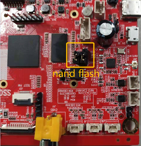
1.1. SSC35XG主板示意图
电源: DC 12V,
调试串口: TTL电平,特率115200


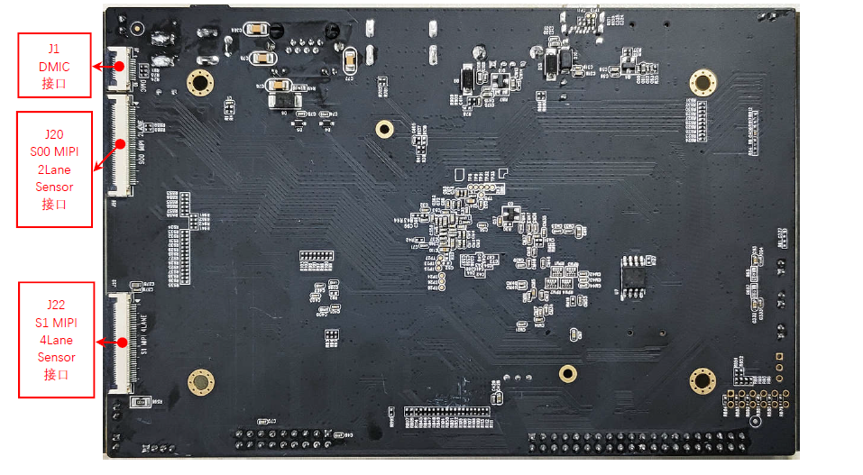
1.2. SSD268G主板示意图
电源: DC 12V,
调试串口: TTL电平,特率115200

2. 准备编译环境
通常我们会以交叉编译的方式进行开发和调试,即“宿主机+目标机”的形式。而宿主机和目标机的连接我们一般采用串口连接或网络连接,如下图所示:
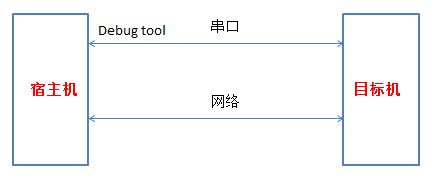
注:我们提供的debug tool作用为读寄存器和烧写Mboot。
2.1. 安装Linux服务器
建议使用Ubuntu 16.04及以上。
2.2. 安装交叉编译工具
boot、kernel、project统一使用一个交叉编译工具。
Glibc:arm-linux-gnueabihf-sigmastar-9.1.0-
3. 编译
本芯片支持nor flash和spi nand flash两种启动方式,因此在SDK中编译有所区分,通过不同的配置文件来实现,SDK中包含了最新的boot和kernel的image,并且脚本打包成可烧录的image。
3.1. 编译boot
# cd $/{Alkaid}/boot
SPI-NOR package
# declare -x ARCH="arm"
# declare -x CROSS_COMPILE="arm-linux-gnueabihf-sigmastar-9.1.0-"
# make mercury6_defconfig;
# make clean;
# make
SPI- NAND package
# declare -x ARCH="arm"
# declare -x CROSS_COMPILE="arm-linux-gnueabihf-sigmastar-9.1.0-"
# make mercury6_spinand_defconfig;
# make clean;
# make
Get image
# cp u-boot.xz.img.bin ${ your_release_path }   // 选择spi-nor时
# cp u-boot_spinand.xz.img.bin ${ your_release_path }// 选择spi-spinand时
3.2. 编译kernel
# cd $/{Alkaid}/kernel
-
SPI-NOR Kernel (ASIC)
CHIP Glibc compiler Uclibc compiler Kernel make config DTS 35XG 512x512MB arm-linux-gnueabihf-sigmastar-9.1.0- mercury6_ssc016a_s01a_defconfig mercury6-ssc016-s01a.dts 268G,4+4lane sensor,512x512MB arm-linux-gnueabihf-sigmastar-9.1.0- mercury6_ssc016a_s01a_dispcam_defconfig mercury6-ssc016-s01a-dispcam.dts 268G,2+4+2lane sensor,512x512MB arm-linux-gnueabihf-sigmastar-9.1.0- mercury6_ssc016a_s01a_dispcam_2+4+2mipi_defconfig mercury6-ssc016a-s01a-dispcam-2+4+2mipi.dts -
SPI-NAND Kernel (ASIC)
CHIP Glibc compiler Uclibc compiler Kernel make config DTS 35XG 512x512MB arm-linux-gnueabihf-sigmastar-9.1.0- mercury6_ssc016a_s01a_spinand_defconfig mercury6-ssc016-s01a.dts 268G,4+4lane sensor,512x512MB arm-linux-gnueabihf-sigmastar-9.1.0- mercury6_ssc016a_s01a_spinand_dispcam_defconfig mercury6-ssc016-s01a-dispcam.dts 268G,2+4+2lane sensor,512x512MB arm-linux-gnueabihf-sigmastar-9.1.0- mercury6_ssc016a_s01a_spinand_dispcam_2+4+2mipi_defconfig mercury6-ssc016a-s01a-dispcam-2+4+2mipi.dts 注:请参考表格和芯片版本做对应的编译。
# declare -x ARCH="arm"
# declare -x CROSS_COMPILE="$compiler"
(exp: uclibc “arm-linux-gnueabihf-sigmastar-9.1.0-“)
# make xxx_kernel_make_config
(exp: make mercury6_ssc016a_s01a_spinand_defconfig)
# make clean;
# make -j8
Get image
# cp arch/arm/boot/uImage.xz ${ your_release_path }
3.3. 编译SDK(ALKAID)
-
SPI-NOR flash package
CHIP Glibc Uclibc 35XG 512x512MB ipc_m6_nor.glibc-9.1.0-squashfs.016a.512x512.bga2_defconfig NA 268G,4+4lane sensor,512x512MB dispcam_m6_nor.glibc-9.1.0-squashfs.016a.512x512.bga2.demo_defconfig NA 268G,2+4+2lane sensor,512x512MB dispcam_m6_nor.glibc-9.1.0-squashfs.016a.512x512.bga2.2+4+2mipi_demo_defconfig NA -
SPI-NAND flash package
CHIP Glibc Uclibc 35XG 512x512MB ipc_m6_spinand.glibc-9.1.0-squashfs.016a.512x512.bga2_defconfig NA 268G,4+4lane sensor,512x512MB dispcam_m6_spinand.glibc-9.1.0-squashfs.016a.512x512.bga2.demo_defconfig NA 268G,2+4+2lane sensor,512x512MB dispcam_m6_spinand.glibc-9.1.0-squashfs.016a.512x512.bga2.2+4+2mipi_demo_defconfig NA 注:请参考表格和芯片版本做对应的编译。
# cd $/{Alkaid}/project方法1:
# . /setup_config.sh xxx_alkaid_build_config
(exp:
./setup_config.sh ./configs/defconfigs/ipc_m6_spinand.glibc-9.1.0-squashfs.016a.512x512.bga2_defconfig)
方法2:
#make xxx_alkaid_build_config
(exp: make ipc_m6_spinand.glibc-9.1.0-squashfs.016a.512x512.bga2_defconfig)

# make image
Get image
# cd ${Alkaid}/project/image/output/images
4. 烧写
4.1. 用uboot烧录程序
-
Run tftp (FTP server) on PC
-
使用tftp工具指向image path:
SDK\project\image\output\images\,并选择正确的网卡。
图4-1
-
连接板子的网口到PC端,连接debug串口工具到PC端,并检查连接的正确性。
-
-
Run tftp (FTP Client) on EVB
板子开机,长按回车,进入bootloader command line. sigmastar 的boot loader。
-
首次烧录请设置IP:(除非ip设置变更或者更换flash)
# set -f gatewayip 192.168.1.1
# set -f ipaddr 192.168.1.127           (设定FTP Client (EVB板子)使用的IP)
# set -f netmask 255.255.255.0
# set -f serverip 192.168.1.100         (设定FTP server (PC) 的IP)
# saveenv
注:
-
为了保证烧录顺利,请保证PC和开发板处于同一网段。
-
请采用静态方式固定分配ip。防止烧录时ip地址跳变。
-
您也可以使用独立网卡使PC端直连开发板,固定该网卡的内网ip地址,并按上述方法设定开发板。
在UBOOT console下执行以下指令即可自动透过ethernet烧录。
4Layer板:
# estar (OR: estar auto_update.txt)6Layer板:
# estar auto_update_6layers.txt
-
-
4.2. 用ISP Tool烧录uboot
本方式适用于空机烧录,或者uboot已经损坏导致无法通过uboot升级的场合。
4.2.1. SPI-NOR-Flash
-
默认分区
No range size IPL 0x00000000-0x00010000 64KB IPL_CUST 0x00010000-0x00020000 64KB MXPT 0x00020000-0x00030000 64KB UBOOT 0x00030000-0x0004F000 124KB UBOOT_ENV 0x0004F000-0x00050000 4KB BOOT 0x00000000-0x00050000 320KB KERNEL 0x00050000-0x00250000 2048KB ROOTFS 0x00250000-0x00650000 4096KB NVRSERVICE 0x00650000-0x00950000 3072KB CUSTOMER 0x00950000-0x01000000 6848KB -
ISP工具烧录
offset Binary放置目录 IPL.bin 0x00000 ${ALKAID}\project\image\output\images\IPL.bin IPL_CUST.bin 0x10000 ${ALKAID}\project\image\output\images\IPL_CUST.bin MXP_SF.bin 0x20000 ${ALKAID}\project\image\output\images\MXP_SF.bin u-boot.xz.img.bin 0x30000 ${ALKAID}\project\image\output\images\u-boot.xz.img.bin 注:6Layer板IPL.bin和IPL_CUST.bin为IPL.EXDDR3_6LAYER.bin和IPL_CUST.EXDDR3_6LAYER.bin,下面选择也要相应更改。
-
烧录步骤
-
执行ISP tool。并且关闭UART terminal,否则无法正常
Connect -
选择SPI tab, 点击
More并且选择类型为SPI -
加载烧录文件并点击
Connect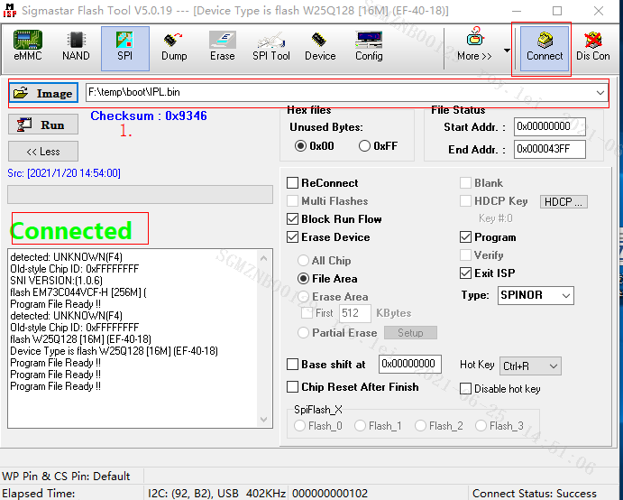
-
加载image “IPL.bin”,并点击’Run’
注:需要勾选
erase file area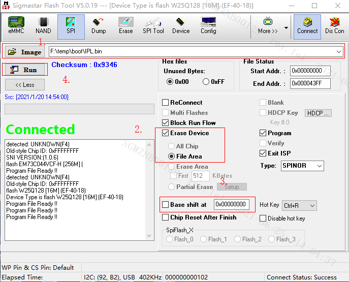
-
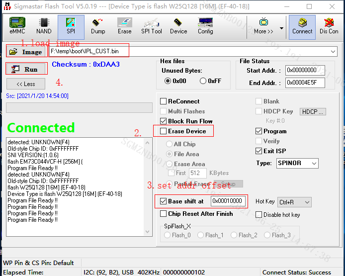
加载 image
IPL_CUST.bin, 取消Erase Device选项。设置Base shiftat 0x10000注: 可能随着版本变化,Base shift的地址以ISP工具烧录表中数据为准。
-
加载image
MXP_SF.bin, 设置Base shiftat 0x20000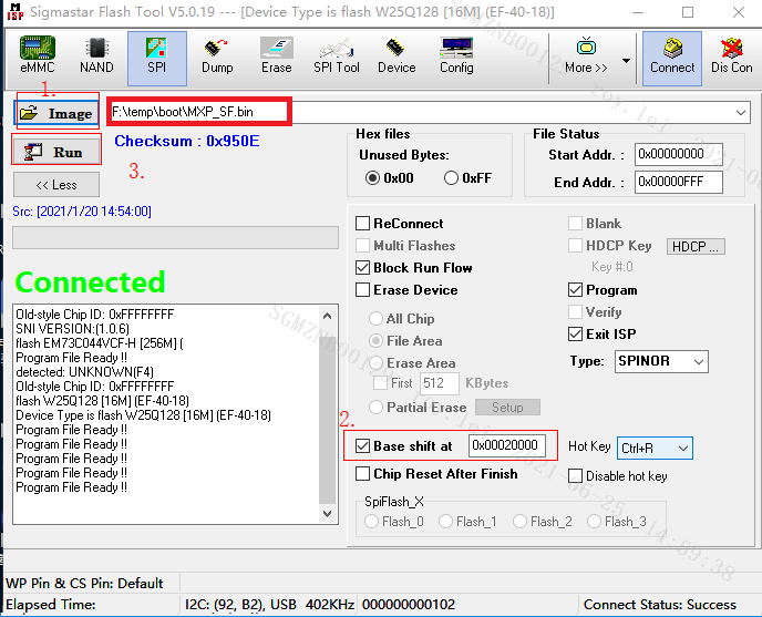
-
加载image
u-boot.xz.img.bin, 设置Base shiftat 0x30000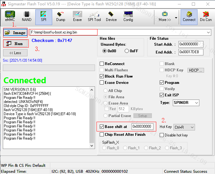
-
重启EVB板子,关闭工具
-
4.2.2. SPI-NAND Flash
-
默认分区
No range size CIS 0x00000000-0x0020000 128KB IPL0 0x00140000-0x00200000 768KB IPL_CUST0 0x00200000-0x00260000 384KB IPL_CUST1 0x00260000-0x002c0000 384KB UBOOT0 0x002c0000-0x00320000 384KB UBOOT1 0x00320000-0x00380000 384KB ENV 0x00380000-0x003c0000 256KB KERNEL 0x003c0000-0x008c0000 5120KB RECOVERY 0x008c0000-0x00dc0000 5120KB rootfs 0x00dc0000-0x013c0000 6144KB UBI 0x013c0000-0x008000000 110848KB -
ISP工具烧录
-
ISP Tool版本
请确定 Flash_Tool版本为5.0.19.exe。
ISP Tool会在首次版本发布的时候一起打包在Tool目录下。
-
Images
Offset Image所在目录 GCIS.bin 0x000000 project\image\output\images\ GCIS.bin IPL.bin 0x140000 project\image\output\images\IPL.bin IPL_CUST.bin 0x200000 project\image\output\images\IPL_CUST.bin u-boot_spinand.xz.img.bin 0x2C0000 project\image\output\images\ u-boot_spinand.xz.img.bin 注:6Layer板IPL.bin和IPL_CUST.bin为IPL.EXDDR3_6LAYER.bin和IPL_CUST.EXDDR3_6LAYER.bin,
下面选择也要相应更改。
-
烧录步骤
-
执行ISP tool。并且关闭UART terminal,否则可能无法正常
Connect
-
选择SPI tab, 点击
More并且选择类型为SPINAND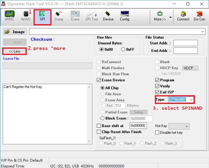
-
加载烧录文件并点击
Connect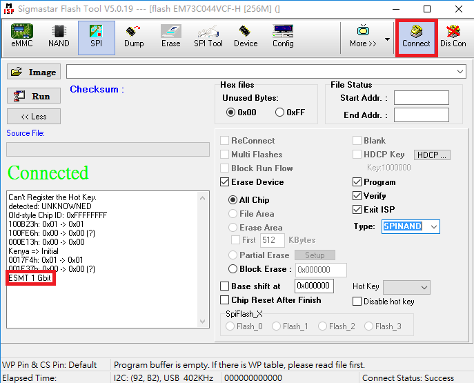
-
加载image
GCIS.bin, 并点击Run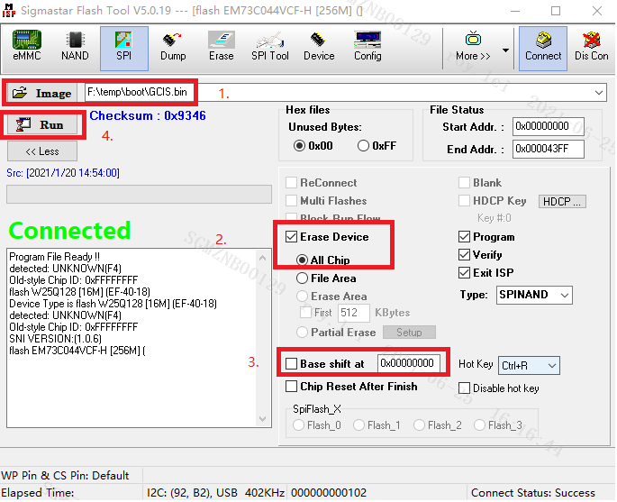
注:需要勾选
erase all chip -
加载 image
IPL.bin, 取消Erase Device选项, 设置Base shiftat 0x140000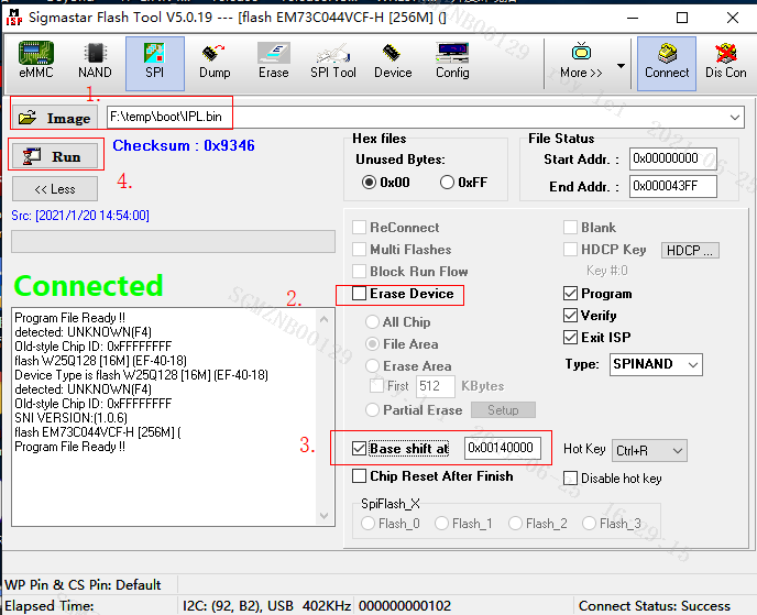
-
加载image
IPL_CUST.bin, 设置Base shiftat 0x200000。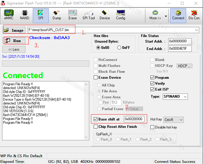
-
加载image
u-boot_spinand.xz.img.bin, 设置Base shiftat 0x2C0000。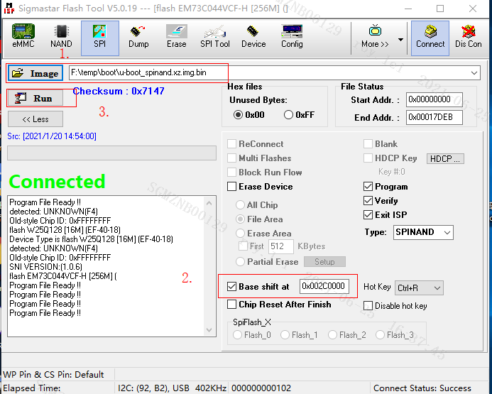
-
重启EVB,关闭工具。
-
-