Sensor Q&A
Q1: Which pins need to be configured for mipi sensor? How to configure them?
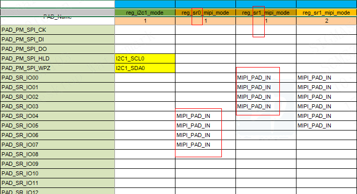
Take the 1lane GC1054 sensor as an example, the pins that need to be configured are as follows:

The clk and data related to mipi are configured in pioneer3.dtsi:
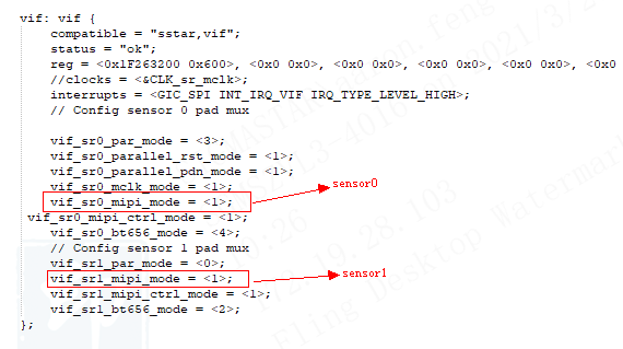
When clk and data of sensor mipi are inconsistent with the chip, you can configure it by csi of dts:
csi {
/* mipi0 2lane setting */
/* Config max lane number */
csi_sr0_lane_num = <1>; // 1: for GC1054 1 lane; 2: for imx307 2 lane
/* Config lane selection */
csi_sr0_lane_select = <1 0 2 3 4>; //<clk d0 d1 d2 d3>; <1 0 2 3 4> for GC1054, <0 1 2 3 4> for imx307
//csi_sr1_lane_select = <1 0 2 3 4>;
/* Config lane P/N swap */
csi_sr0_lane_pn_swap = <1 1 1 1 1>;
//csi_sr1_lane_pn_swap = <1 1 1 1 1>;
};
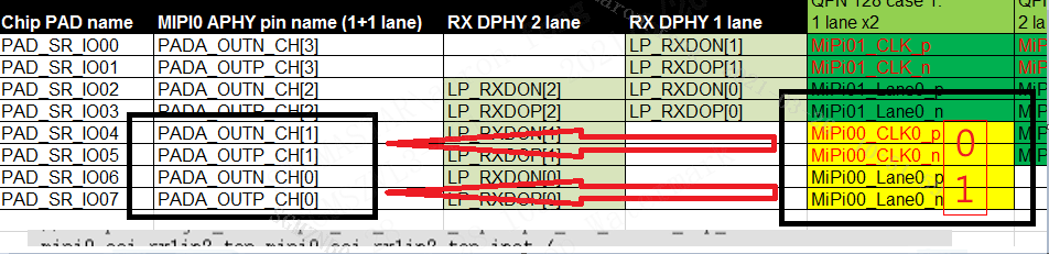
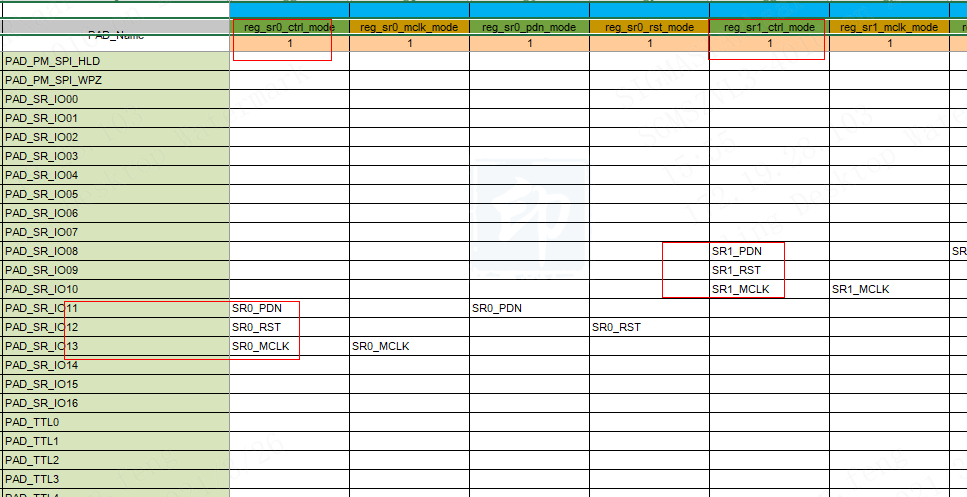
csi_sr0_lane_select corresponds to an array in the driver. The array elements are the coordinates corresponding to PADA_OUT_CH. The positions in csi_sr0_lane_select correspond to MIPI CSI\< CLK Lane0 Lane1 Lane2 Lane3>
Take the gc1054 connected to 1lane as an example, just configure clk and lane0, and the corresponding clk and lane0 indexes are 1,0 respectively, so the value of csi_sr0_lane_select is \< 1 0 x x x>; The positions in csi_sr0_lane_pn_swap correspond to whether PADA_OUT_ \< CH0 CH1 CH2 CH3 CH4> needs P/N crossover instead of the order of \<CLK Lane0 Lane1 Lane2 Lane3>, the 5 indexes of swap correspond to PADA_OUT_CH, and do not change with the lane order of select
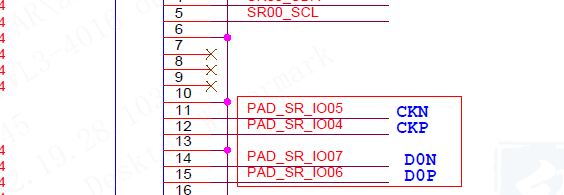
As above, the original PAD_SR_IO07 should be connected to mipi P, but the actual connection is the sensor N signal, so the value of csi_sr0_lane_pn_swap should also be 1 for swap.
mclk, powerdown, reset pin and i2c pin are configured in pioneer3.dtsi:
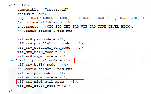

1: i2c1, refer to i2c reference.
Q2: Where to configure the sensor's i2c address?
It is configured in the sensor driver.
Note: The writeaddr of i2c is filled in the sensor driver, not slave addr, writeaddrs = slave addr \times 2.

Q3: How to compile the new Sensor driver into image?
The source code and sdk folders obtained by user are not compiled together with the project. After the sensor driver is added, you need to make SensorDriver in sdk/driver to compile the ko file, and then replace it under $(PROJ_ROOT)/release/$(PRODUCT) /$(CHIP)/common/$(TOOLCHAIN)/$(TOOLCHAIN_VERSION)/modules/$(KERNEL_VERSION).
...