MISC Q&A
Q1: How to support SPI panel on SSD210?
The hardware related padmux on the demo board is as follows:

The following changes need to be made for HW:
-
Add the following changes in kernel DTS (kernel/arch/arm/boot/dts/pioneer3-ssc021a-s01a-demo-padmux.dtsi)
, , , -
Add the following changes in test demo(smartdisp_demo / P3_ReleaseDemo/panel/SpiPanel/)
src/spi_operation.c
    static const char *device = "/dev/spidev1.0";
src/spi_panel.c
    #define RS_GPIO_PIN (20)
    #define RST_GPIO_PIN (21)
    #define BL_GPIO_PIN (5)  //Backlight 没有更改, 因为SSD210 demo board不需要控制这个
Q2: When making the master, the nandid of SPINAND.INI is not the actual flash id. Why does the master work normally after burning?
When making the master, it will look for the support of this flash in the flashlist of cis according to nandid. If there is a corresponding ID, it will be initialized according to the flash parameters corresponding to the filled nandid.
It is okay if the parameters of the two flashes are not much different. But it is recommended to fill in nandid according to the actual flash id!

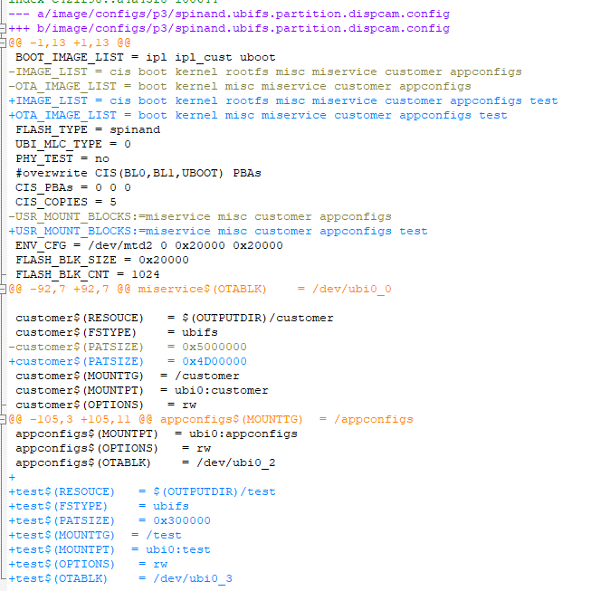
Q3: How to dynamically adjust cpu frequency?
Method 1: Open the required cpu frequency in kernel\arch\arm\boot\dts\pioneer3.dtsi in the kernel dts (if you need to fix a certain frequency, you only need to open the corresponding one)
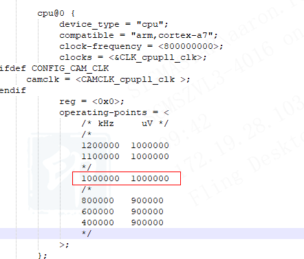
Method 2: Configure as follows in the shell terminal (provided that the corresponding option is turned on in dts, it will only take effect temporarily and only used for debug.)
echo 1000000 > /sys/devices/system/cpu/cpufreq/policy0/scaling_max_freq
echo 1000000 > /sys/devices/system/cpu/cpufreq/policy0/scaling_min_freq
Note: When the cpu frequency is changed, the corresponding core voltage must be adjusted. The current driver is to set the gpio to adjust the core voltage in kernel\arch\arm\boot\dts\pioneer3.dtsi, and you need to make sure that it is not used for other purposes.
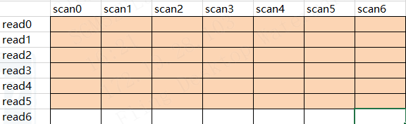
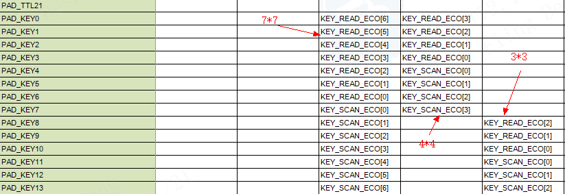
Q4: 7*7 keypad config, actually use 6*7, can I use the remaining pins for other purposes?
Yes, you can. The mapping relationship between the specific keypad pin and key is as follows:
Q5: What is the difference between PSPI and SPI? What is the difference between PSPI connect panel and sensor?
PSPI is a proprietary spi protocol of SStar, which supports master/slave mode, and the maximum CLK is 216Mhz.
Note: The master needs to be divided by two, the maximum clk is 216/2=108Mhz; The clk received by the slave is 4 times that of the sent, that is, the maximum pclk that can be received is 216/4=54Mhz.
The line sequence for connecting to panel is as follows:
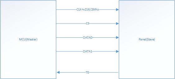
Use TE to control the synchronization timing, and the MCU will send the image after the panel sends the TE signal. The set CLK needs to meet >= panel htotal * panel vtotal *fps
The line sequence for connecting to sensor is as follows:

The default is to connect sensor, sensor cs to ground, and the MCU can ignore cs pin.
Note: CLK sent by sensor must be less than 54M, and MCLK sent to sensor must also be within the receiving range of sensor.
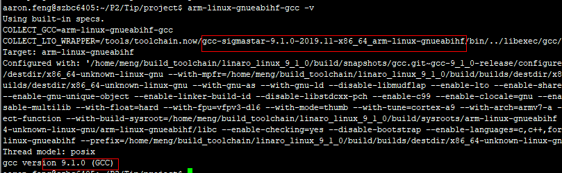
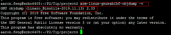
Q6: How to determine the version of gcc & libc & binutils corresponding to toolchain?
gcc:
libc:
project\release\dispcam\p3\common\glibc\9.1.0\package\libc-2.30.tar.gz
binutils:
ToolChain source path:https://git.linaro.org/toolchain
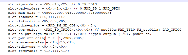
Q7: Does SDIO wifi reboot need to rst when booting? How to achieve it?
There are two power supply methods to connect SDIO wifi:
-
Continuous power supply, reboot relies on rst pin to reset the wifi module
-
Power supply through the power pin of sdio, when rebooting, the sdio driver internally relies on the power pin to reset the wifi module
Both of the above are resetting the wifi module to reboot, and PAD_SD_GPIO0 is used for the power and rst pin of the main control terminal. When the power supply is continuous, PAD_SD_GPIO0 is connected to the rst pin of the wifi module;
When the sdio power pin is powered, PAD_SD_GPIO0 is connected to the powerpin of the wifi module. Set the power on/power off delay in dts as follows to control the time of wifi init after rst is pulled low and pulled high (unit: ms)
Q8: How to add ubi partition?
-
Select partition profile
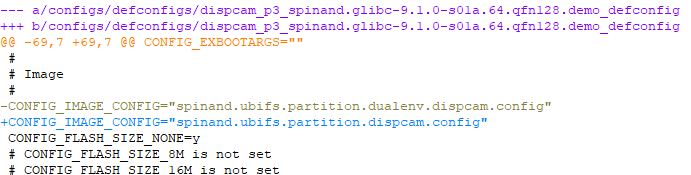
-
Create the mounted partition directory and the files to be placed, take project/board/test/test into the test directory as an example

-
Add new partition config info
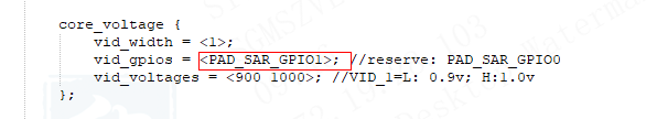
Q9: How to fix the cpu voltage? After fixing, can the pin that dynamically adjust the core voltage be used as gpio?
The pin can be used as gpio.
case 1: fix the frequency to 1G
-
Fixed cpu frequency in
kernel\arch\arm\boot\dts\pioneer3.dtsi.
-
Disable CONFIG_SS_VOLTAGE_CTRL in kernel config.
-
Fix the voltage hardware and then measure: CPU 1G -> 1.0V (from power-on to IPL/UBOOT/KERNEL has been maintained at 1V)
case 2: fix the frequency to 800M
-
Fixed cpu frequency in
kernel\arch\arm\boot\dts\pioneer3.dtsi.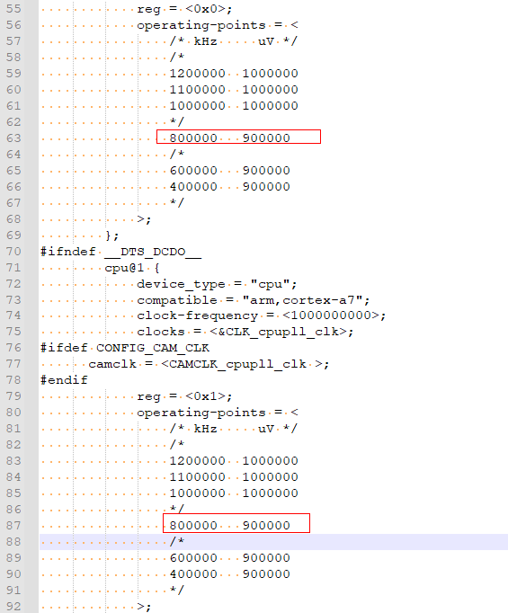
-
Disable CONFIG_SS_VOLTAGE_CTRL in kernel config.
-
Fix the voltage hardware and then measure: CPU 800MHz -> 0.9V (from power-on to IPL/UBOOT/KERNEL has been maintained at 0.9V)
case 3: Dynamic frequency (1G/800M)
-
Fixed cpu frequency in
kernel\arch\arm\boot\dts\pioneer3.dtsi.For example, fixed to 800M.
-
Enable CONFIG_SS_VOLTAGE_CTRL in kernel config.
-
The pin that dynamically adjusts the core voltage has been connected to the relevant circuit, control voltage, and measure:CPU 1G -> 1.0V(from power-on to IPL/UBOOT/KERNEL has been maintained at 1V)
-
CPU 800MHz -> 0.9V or CPU 1G -> 1.0V(It controls by KERNEL according to relevant conditions, at 1G or 800M 1V/0.9V)
The frequency of cpu can be viewed by
cat /sys/devices/system/cpu/cpufreq/policy0/cpuinfo_cur_freqcpu loading:
...