PSPI Q&A
How to use the PSPI module to light up the SPI serial screen?
Get image data from sensor through PSPI module, or transmit image data to panel through PSPI.
Note: Sensor can only be connected to PSPI 0, and panel can only be connected to PSPI 1. See PSPI API for details.
Take PSPI to light up the SPI serial port panel as an example, the panel Driver IC is ILI9340X.
-
Configure padmux according to schematic and check list.
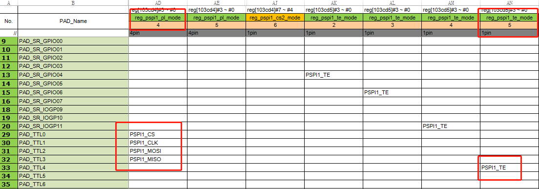
Create a new
padmux.dtsiinkernel/arch/arm/boot/dts, add the following content: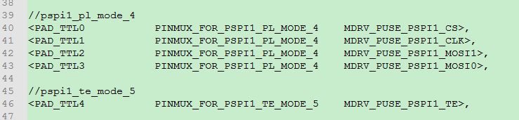
-
Configure the PSPI module and initialize panel
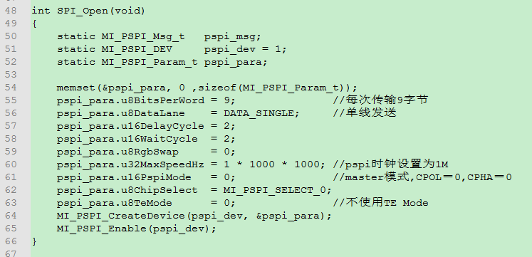
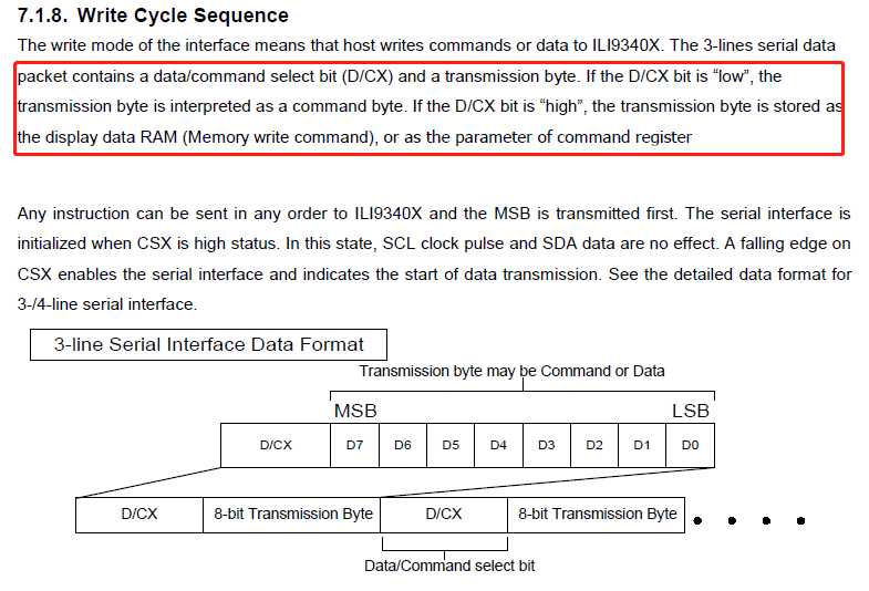
According to the data manual of the panel, the 3-Line SPI mode uses 9bits for transmission, and the highest bit controls the sending of 0: command/1: data.
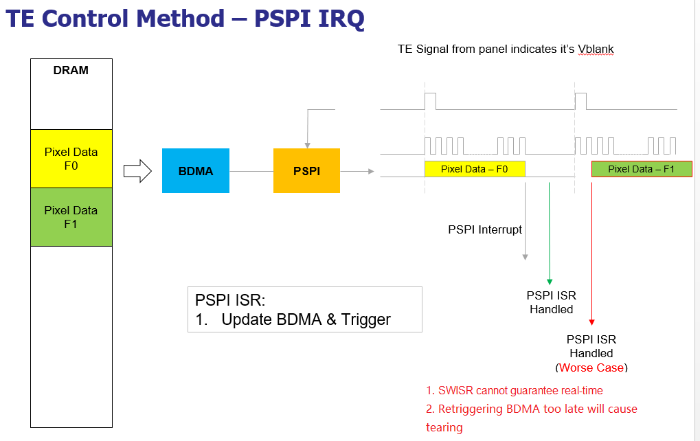
ILI9340X supports TE mode, which is enabled by register config. The TE signal is the vertical synchronization signal feedback by the panel. The PSPI TE Mode Flow is as follows. The data is sent to the Panel via PSPI on the rising edge of the signal:
Set
MI_PSPI_Msg_tand use MI_PSPI_Transfer to transfer data to Panel. As follows, in order to distinguish commands/data, the 9th bit is set to 0 or 1.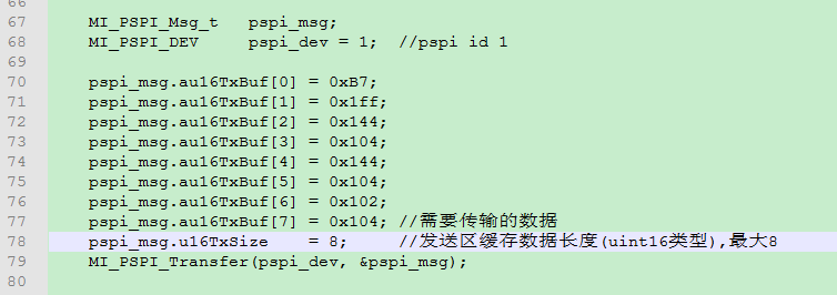
According to the panel default configuration or data manual, use the above method to send the relevant commands to the Panel to initialize the Driver IC.
-
Use PSPI to output images
Use
MI_PSPI_SetDevAttrto reconfigure PSPI parameters. When sending a command to initialize the panel, the TE mode is disabled, the clock is 1M, and the transmission is in single-wire mode; the TE mode is enabled when data is output, and the clock frequency is increased, and the two-wire mode is used for transmission to improve transmission.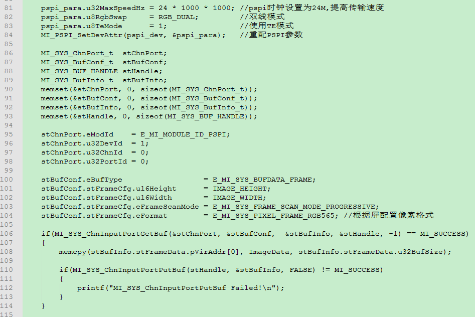
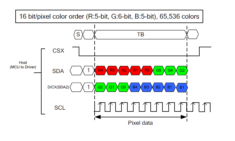
First copy an image data to the DRAM applied by PSPI, and PSPI will send the image to the Panel after receiving the TE rising edge signal. ILI9340X supports SPI two-wire mode, which needs to be opened by command.
...