TFT-LCD Driver Reference
1. Overview
This article is a reference for Spi interface TFT-LCD driver.
2. Spi Panel Driver Config
-
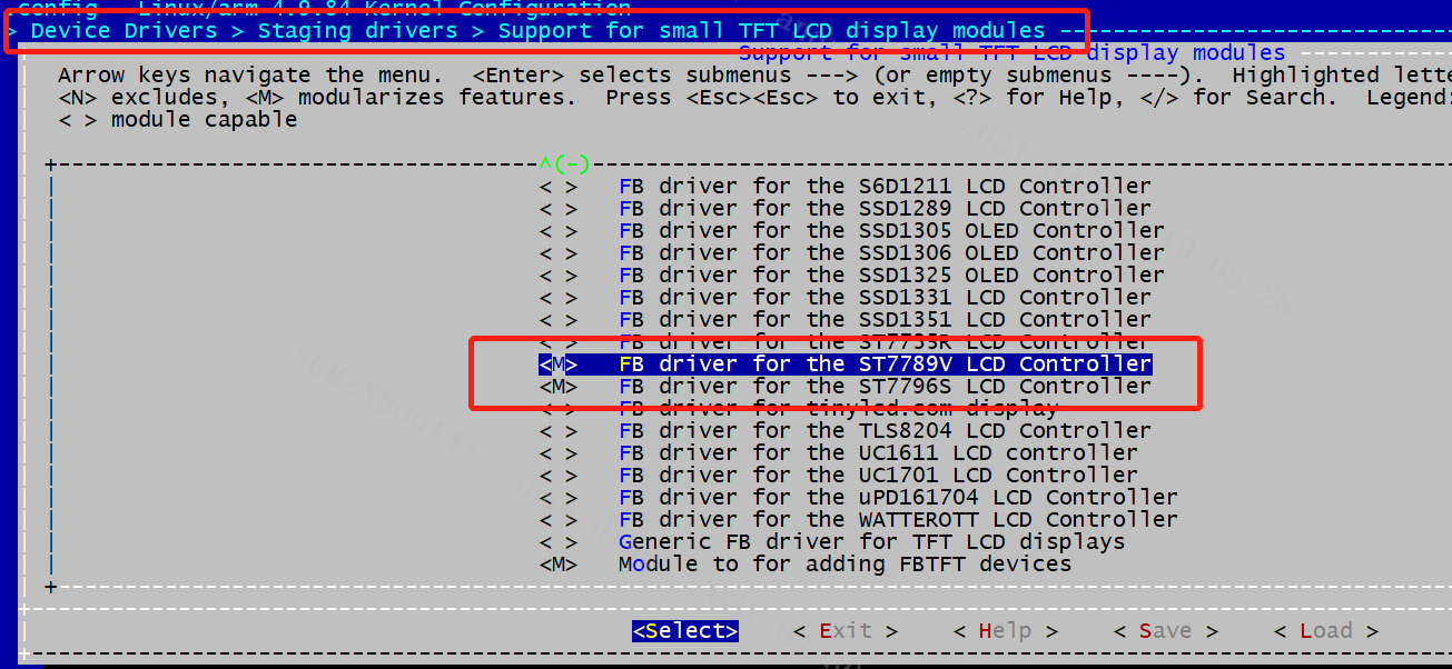
Enable fbtft config in Kernel menuconfig, compile the marks in the figure into module.
-
Add corresponding config in Dts

Install with insomod after compilation.
-
Remove the original fb module
Remove
insmod /config/modules/4.9.84/fbdev.koincustomer/demo.sh``insmod /config/modules/4.9.84/fbdev.koand restart.(If there is zkgui, please also remove it) -
Load the fbtft module after restart
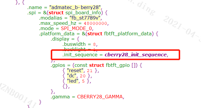
insmod /config/modules/4.9.84/fbtft_device.ko busnum=1 name=admatec_b-berry28 cs=0 gpios="reset:21,dc:20" custom=1 speed=40000000 width=240 height=320 buswidth=8 mode=0 debug=7 dma=0name=admatec_b-berry28 should be the same as the name of fbtft_device_display displays[] in the driver.

Note: spi timeout will be report if the speed parameter is too large, please reduce the value of speed.
-
Load the corresponding TFT driver
insmod /config/modules/fb\_st7796s.koA node of dev/fb0 will be generated, and you can draw directly on fb.
-
-
Modify according to the panel settings
-
Panel initialization
Fbtft-core.c
fbtft_probe_common() -> fbtft_register_framebuffer() -> fbtftops.init_display()Use the initialization parameters of the following array to initialize the panel.
Other settings are in fbtftops.set_var()/fbtftops.update_display()fbtftops.set_gamma().
-
Refresh
The upper layer refreshes fb through ioctl(g_fbFd, FBIOPAN_DISPLAY, &vinfo), corresponding to the bottom layer fbtft_update_display() -> fbtftops.write_vmem() -> fbtft_write_vmem16_bus8()- > fbtftops.write -> fbtft_write_spi()
Note: spi sends data directly to the panel, but the data sent by RGB565 or RGB888 is not the same. The data sent by the upper layer to the driver must conform to the panel data format.
-
-
ZKGUI needs to export ZK_GFX_ENABLE=0, please disable gfx