UART REFERENCE
1. Overview
This article mainly introduces how to configure and use uart in uboot and userspace.
Table 1-1 Specifications
| Peripherals | Maximum baud |
|---|---|
| 1 FUART 3 UART UART0 is used as the console | UART clock is up to 172MHz, theoretical max baud: 172M/16 = 10.7Mbps |
2. Use UART in Uboot
2.1. Uart Driver Analysis
The path of UART driver code is boot/drivers/mstar/uart/ms_serial.c.
Table 2-1 API function
| Function name | Description |
|---|---|
| ms_uart_putc | Send a character which type is char. |
| ms_uart_getc | Recive a character which type is char. |
| ms_uart_init | Initialize the serial port |
| ms_uart_padmux | Configure uart's padmux and peripheral clock |
2.2. Configure UART PADMUX
Refer boot/drivers/mstar/uart/pioneer3/uart_padmux.c to configure UART PADMUX. The pin and PADMUX mode used by UART/FUART in default are list in that file.
You can view the CheckList to select the pin as UART and modify the corresponding PADMUX mode.

ms_uart_padmux will configure the corresponding pins, select the uart controller and enable the uart peripheral clock according to PADMUX mode.
2.3. Test UART Communication
The uart test command is introduced in boot/common/cmd_mstar.c.
You can refer the implementation of do_uart to write the code.
Select a group UART to be test, and then connect the tx and rx of UART, finally, run the commamd to test the communicatin.
Take uart1 as an example, the commands are as follows:
# uart init 1 115200   //Initialize UART1 and set the baud as 115200

# uart lookback 5
If the sent and the reviced character are the same, the UART communication is normal.
3. Configure UART in Kkernel
The following modes and pins are recommended.
| UART Group | Mode | TX | RX | CTS | RTS | DEV |
|---|---|---|---|---|---|---|
| Fuart | 6 | PAD_GPIO5 | PAD_GPIO6 | PAD_GPIO7 | PAD_GPIO8 | /dev/ttyS2 |
| Uart1 | 8 | PAD_GPIO1 | PAD_GPIO2 | -- | -- | /dev/ttyS1 |
| Uart2 | 6 | PAD_GPIO3 | PAD_GPIO4 | -- | -- | /dev/ttyS3 |
3.1. Configure DTS
Open Kernel/arch/arm/boot/dts/pioneer3.dtsi to configure the DTS.
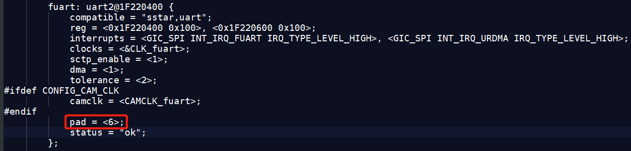
Configure fuart mode:
Configure uart1 mode:

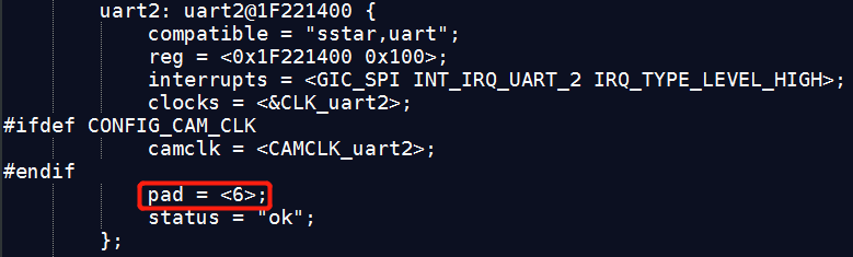
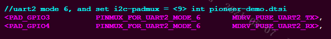
Configure uart2 mode:
3.2. Configure PADMUX
Open Kernel/arch/arm/boot/dts/pioneer3-ssc020a-s01a-demo-padmux.dtsi to configure PADMUX according the selected mode.
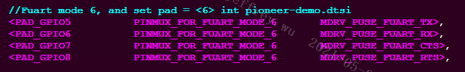
Configure fuart padmux:
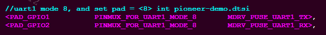
Configure uart1 padmux:
Configure uart2 padmux:
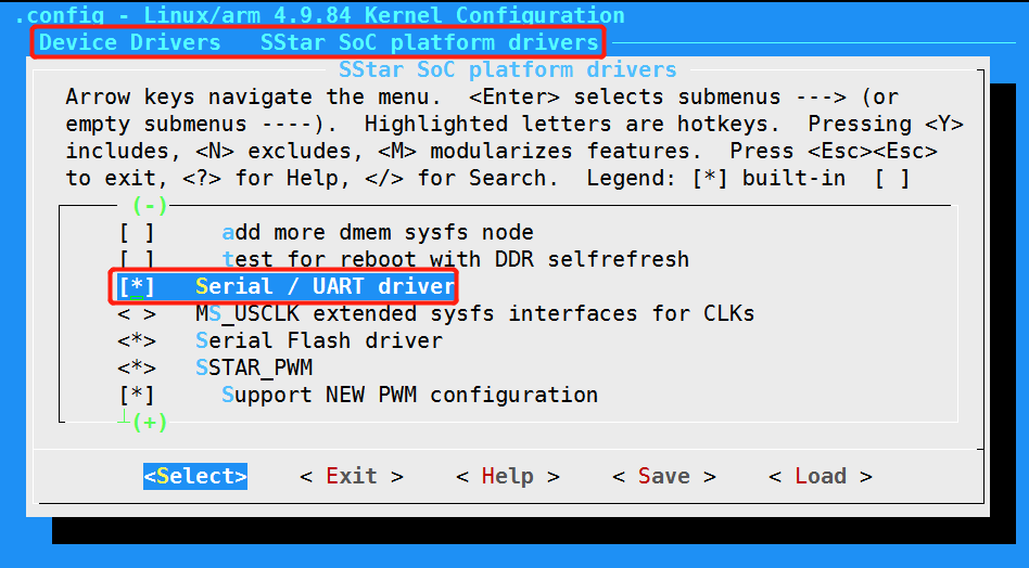
3.3. Enable UART Driver
Enable the following options in menuconfig to open UART function and configure the driver.

4. Use Uart in User Layer
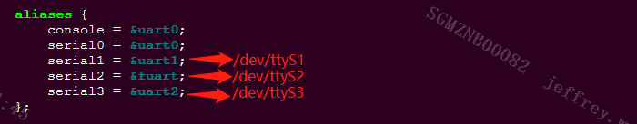
4.1. Check the UART used /dev/ttySx
打开如下dts文件,确认uart对应的是哪路serialx,serialx对应的就是/dev/ttySx。
Open kernel/arch/arm/boot/dts/pioneer3.dtsi to check the serialx corresponding to uart, which corresponds to /dev/ttySx.
4.2. Use UART in Application Layer
Sample code for testing: uart_main.c.
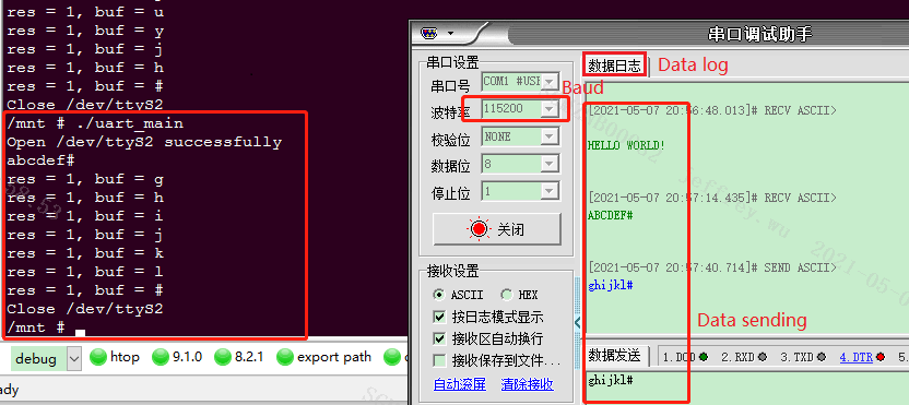
Use # arm-linux-gnueabihf-gcc -o uart_main uart_main.c to build the source file, generate an executable bin file and test the UART communication.
Connect serial port of the demo board to the PC, and set the baud to 115200. Copy the bin file to demo board, and run # ./uart_main in shell. At this time, the PC's serial port assistant will receive "hello world!", enter # in shell to end, and the application will send the string received in shell to PC by uart; Enter # in the serial port assistant of PC to end, and the characters sent by the serial port assistant will be printed in shell.
4.3. Fuart Flow Control
To test fuart communication, you need to enable flow control in sample code, and enable CTS and RTS.

Run uart_main, “hello world!” will not be sent by fuart immediately when CTS=1, but when the CTS pin connect to ground, the PC serial port assistant will recive it, so the CTS function is normal if thing going well; RTS=0 when the RTS signal displayed in oscilloscope, and when fuart's fifo data buffer full, RTS pulls up to tell the device to stop sending. The RTS signal suddenly changes at the rising edge when the serial port assistant sends character string which more than 30bytes. At that case, the RTS function is normal.
4.4. Check PADMUX Config
When the UART communication is abnormal, please check the connection is correct first, then check whether PADMUX config is correct by read the register.
The padmux table in the kernel driver file lists the register base address, offset address, and valid bits. Open kernel/drivers/sstar/gpio/pioneer3/mhal_pinmux.c to find the pin.
The following figure shows the register info when fuart is configured as PINMUX_FOR_FUART_MODE_6.

| Base address | PADTOP_BANK | 0x103C |
|---|---|---|
| Offset address | REG_FUART_MODE | 0x6E |
| Valid bits | BIT10|BIT9 | 0x0600 |
Run /customer/riu_r 0x103C 0x6E in demo board to read the value of register. The FUART PADMUX register configuration is correct what if the value is 0x0600.
Note: The priority of GPIO MODE is higher than FUART MODE. Only when the pin of this group is not GPIO MODE can it be configured as FUART MODE.
5. Uart Driver Architecture And Debug Method
The Uart driver framework is as follows:
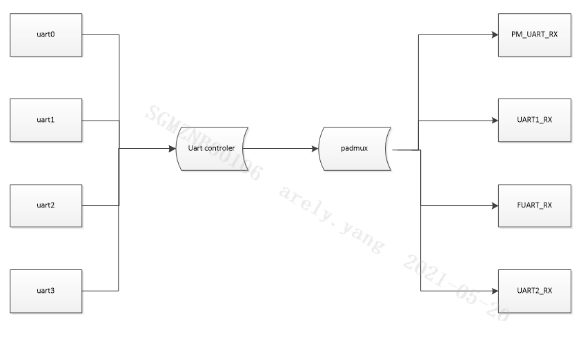
It can be seen from the above that the driver mainly connects the uart controller and the corresponding pad in series.