SYSTEM PARTITION
1. Partition Introduction
1.1. Flash Partition Introduce
The partition table is saved in the partition_layout.txt output of the compilation. As shown in the figure below, the partition config may be different in different software versions. Please refer to the currently compiled code:
SPI-NOR partition table information:

SPI-NAND partition table information:

CIS:
Spinand is stored in the flash 0 address, and Nor is stored after the IPL partition, it contains three parts:
-
GCIS
It contains a general flash info, in order to make the rom code adapt to most flash parameters, boot smoothly enter the IPL.
-
flash info
SNI, save some basic information of flash, such as block page count, block count, etc., which will change according to the type of flash.
-
partition info
PNI, saved partition information, only IPL/IPL_CUST/RTK can see the information in the PNI. When the linux system is running, the partition information is replaced with uboot's mtdparts to perform the linux native partitioning process.
In addition to the BOOT partition used to make One bin in mtdparts, which can be different from the PNI, the other partition information must be the same as that in the PNI. From the PNI, we can see that the BOOT partition distribution in mtdpars is more detailed, such as the specific location of
IPL/IPL_CUST/UBOOT.
IPL/IPL_CUST:
After the CPU is powered on, the rom code runs first. The code is stored in a special ROM and is read-only. After the ROM code runs, it will find the location of the IPL and resolve the location of the IPL address. The difference between NOR and SPINAND will be introduced in the following chapters. The main function of IPL is to do some basic hardware initialization, such as setting the current DDR parameters, and GPIO/IIC related.
There are some common hardware modules during IPL initialization. IPL_CUST will initialize customized hardware executable binary files according to the actual situation of the current board, such as customized GPIO, IIC configuration.UBOOT: Store UBOOT binary files.
ENV: Store the environment variables of UBOOT。
LOGO: Store the relevant configuration of the boot logo.
MISC: The partition where the system configuration script is stored is the littlefs file system, which contains bootlogo, screen parameter and other related init configuration and resource files. If it is configured, there is no need to add a LOGO partition. For details, please refer to BOOT LOGO Reference.
KERNEL: Store the binary files of the kernel.
**ROOTFS:**The root directory file system.
UBI: The content of UBI will not be displayed in the partition table above. UBI will create multiple sub-partitions in ubifs format, which you can create by yourself. Spinand's miservice partition is placed in UBI.
APPLICATION/CUSTOMER: User extended partition.
**MISERVICE:**Store the ko, so, of the MI module, config scripts and bin.
1.2. MISERVICE Partition
The contents of the MISERVICE partition are mounted to the root directory /config/. The files in the following table must keep the same path, otherwise the system may not start.
└── config
    ├── board.ini                                 ---->保存当前板子的信息
    ├── config_tool                         ---->mi sys初始化mmap内存的应用
    ├── dump_config -> config_tool          ---->dump config 应用,config_tool的symbol link。
    ├── dump_mmap -> config_tool                ---->dump mmap应用,config_tool的symbol link。
    ├── fbdev.ini                           ---->Framebuffer 配置,若无fbdev需求可删除。
    ├── iqfile
    │   ├── imx307_iqfile.bin
    │   ├── iqfile0.bin -> imx307_iqfile.bin      ---->Sensor IQ相关的bin
    │   ├── iqfile1.bin -> imx307_iqfile.bin
    │   ├── iqfile2.bin -> imx307_iqfile.bin
    │   ├── iqfile3.bin -> imx307_iqfile.bin
    │   └── isp_api.xml
├── mmap.ini                            ---->Mmap。Mmap可以参考《Memory Layout介绍》
    ├── model                                     ---->模块相关配置,可以删除。
    │   ├── Customer_1.ini
    │   ├── Customer_2.ini
    │   └── Customer_auto_test.ini
    ├── modules                                    ---->系统KO存放路径。
    │   └── 4.9.84
│       ├── cifs.ko
        ……
    ├── pq                                        ---->NVR显示PQ相关。
    │   ├── Bandwidth_RegTable.bin
    │   ├── Main.bin
    │   └── Main_Ex.bin
    ├── terminfo                                  ---->Console显示相关。
    │   └── v
│       ├── vt100
        ……
    └── venc_fw                                   ---->Encoder的firmware
        └── chagall.bin
2. CIS Partition
The partition of CIS is divided into three parts, starting from address 0 of flash, they are GCIS, PNI, and SNI.
2.1. PNI
The partinfo.pni is dynamically generated by pnigenerator, and it will be saved as a separate file in image/boot/ after compilation.
Code and compilation:
Source path of pnigenerator:
project/image/makefiletools/src/pnigenerator/pnigenerator.c
Compile with gcc on the server:
gcc pnigenerator.c -Wall –o pnigenerator
Example:
pnigenerator -c 1024 -s 0x20000 -a "0x140000(CIS),0x60000(IPL),0x60000(IPL_CUST),0xC0000(UBOOT)" -b "0x60000(IPL),0x60000(IPL_CUST),0xC0000(UBOOT)" -t "0x60000(ENV),0x20000(KEY_CUST),0x500000(KERNEL),0x500000(RECOVERY),0x600000(rootfs),0x60000(MISC),-(UBI)" -o /home/malloc.peng/hc/project/image/output/images/boot/partinfo.pni
Parameter definition:
-r: Read the partition in the target PNI file and print it.
-c: All partitions account for the BLOCKS of FLASH.
-s: A BLOCK data size of FLASH, unit: byte.
-a: A collection of BOOT PART partitions, expressed in the grammatical format of mtdparts.
-t: A collection of SYS PART partitions, expressed in the grammatical format of mtdparts.
-o: File name and path of the generated PNI file
The PNI file is not statically stored in the packaged project, it is determined by the compilation configuration used by the user, and is generated by pnigenerator according to the parameters of the incoming configuration partition.
PNI passes the "-a" and "-t" parameters into the partition information to generate the file project/image/output/images/boot/partinfo.pni.
2.2. SNI
The path where SNI is stored in the ALKAID board:
-
SPINAND:
project/board/$(CHIP)/boot/spinand/partition/flash_list.sni -
NOR:
project/board/$(CHIP)/boot/nor/partition/flash_list.nri
2.3. GCIS
GCIS is a special SNI, which contains general FLASH initialization parameters, which are used to read the parameters of starting FLASH for the solidified code in ROM CODE, so as to read the data of IPL and start the BOOT stage into IPL.
The path where SNI is stored in the ALKAID board:
-
SPINAND:
project/board/$(CHIP)/boot/spinand/partition/flash.sni -
NOR:
project/board/$(CHIP)/boot/nor/partition/flash.nri
2.4. CIS Partition Data Structure
The CIS partitions are spliced by GCIS, PNI, and SNI in a specific way, and are dynamically generated by Makefile scripts.

The above figure shows the CIS data structure. Both GCIS and PNI are smaller than the size of a PAGE, so they each occupy a PAGE. SNI_LIST saves all FLASH information, it will be added to the back of PAGE1. The PAGE size of NOR FLASH and SPINAND FLASH is related to FLASH specifications, please refer to FLASH SPEC for details.
The size of PAGE can be defined according to the cis$(PGSIZE) defined in the config script of the partition.
In the process of making the partition burning script, the bin making and burning of the CIS partition is one of the steps. The making of the CIS bin is executed in the target cis_nofsimage in project/image/image.mk. The cis.bin will be generated in project/image/output/images/ after production, including GCIS/PNI/SNI.
3. Partition Config
3.1. Note Before Config
The partitions of spi-nor flash and spi-nand flash can be classified into two categories:
-
Recommended unmodifiable boot
-
Changeable sys
The partition changes introduced in this chapter are all in sys, including configuration scripts to change the order of partitions, package partitions, and generate burning scripts. If the user has your own packaging and burning process, please ignore this chapter. Special note: The files specially marked in the miservice partition in the previous chapter need to be placed in the specified path for the system to run. When creating the partition, please create /config/ in the root directory to place the relevant files.
3.2. Script Config
Partition changes are divided into partition production, packaging and partition burning script production.
The following two branches of the flowchart, the left is the partition production and packaging process; the right is the partition burning script production process, which only supports tftp upgrade script, does not support usb upgrade script production. 
3.3. Partition Config Script
Script location for partition config:
project/image/config/$(CHIP)/xxx.partition.config
All the codes related to partition adjustment are implemented by this partition configuration information script, which will have many copies, and each different chip, spinand partition or spinor partition will have its own partition config file.
The partition config file used by the project can be found through build config, and the defined variable is IMAGE_CONFIG.
In this configuration script, the variable IMAGE_CONFIG can find the corresponding partition configuration script.
In the config script file, each partition is represented by a set of variables, as shown below:

The CIS partition stores a set of specified partition configuration raw data, which is a special partition generated by a special command.
The partitions are divided into whether they have a file system or not. Their packaging and burning scripts are different. The creation of a partition image file with a file system can be processed by tools in a unified manner, and a partition without a file system needs to be processed separately for each partition.
The above introduced some partitions used by the public version, such as the miservice partition, which can be configured as a read-only squashfs file system, or it can be made into jiffs2 or ubifs. All partitions used by the public version are used by the xxx.mk script to fill the mirror. The content of the file inside the file, miserive.mk will copy the ko and so required by mi to the target folder, rootfs.mk will copy the files needed in the root file system to the target folder, for example, rootfs.mk needs to be copied the busybox tool required by linux.
Examples of miserive partition config:
3.4. 分区位置变更
Partition Location Change
In the CIS partition configuration, the variables cis(BOOTTAB0), cis(BOOTTAB1), and cis$(SYSTAB) are used to configure the partition information.
cis(BOOTTAB0) and cis(BOOTTAB1) are used to specify the A-B partition in the production of one bin, and identify whether the BOOT used is active in the PNI. At present, the A-B partition is introduced in the spi-nand partition, and BOOTTAB0 is active partition, when BOOT0 is abnormal in programming or a bad block appears, it will jump from BOOT0 to the backup partition of BOOT1, and re-identify the active partition in the PNI, and it will automatically run to the active partition next time it starts. .
BOOTTAB0, BOOTTAB1, and SYSTAB are the definitions of the partition table. The syntax format it uses is supported by mtdparts, and the format is as follows:
partition0_size(partition0_name), partition0_size(partition0_name),……
The description format of CIS and IPL partition:
0x14000(CIS),0x60000(IPL)
Each partition is separated by ",". If the starting position of the partition is not specified, it will start from the first partition, and the default will start from address 0 of FLASH. If you need to configure from the specified location of the partition, follow the syntax format:
partition0_size@offset(partition0_name)
After the starting position of the partition is specified, the starting position of the added partition will increase one by one after the current partition if no position is specified.
If the current partition is the last one, you can select the size of the adaptive partition.
For example, the UBI partition of spinand is at the end of the partition table, and it can be expressed as follows:
xxxx(xxxx), xxxx(xxxx),-(UBI)
The parsing logic of the partition table will refer to the size of the current flash configuration to adapt to the size of the UBI.
The modification of the partition location is to change the location of cis(BOOTTAB0), cis(BOOTTAB1), and cis$(SYSTAB). The partition of the BOOT part will not change, generally SYSTAB will change.
3.5. Add/Modify/Delete jiffs2 Partition
Use jiffs2 as a readable and writable partition file system on the flash of spinor. The relevant configuration of the customer partition is defined as follows:
customer$(RESOUCE)   = $(OUTPUTDIR)/customer
customer$(FSTYPE)    = jffs2
customer$(PATSIZE)   = 0x5C0000
customer$(MOUNTTG)  = /customer
customer$(MOUNTPT)  = mtd:customer
customer$(OPTIONS)   = ro
customer$(MTDPART) = $(customer$(PATSIZE))(customer)
customer$(OTABLK) = /dev/mtdblock6
-
customer$(RESOUCE):
The contents of the folder where the source files to be packaged are located are filled in by the customer.mk script.
-
customer$(FSTYPE):
The file system type of the package.
-
customer$(PATSIZE):
Partition size.
-
customer(MOUNTTG)、customer(MOUNTPT)、customer$(OPTIONS):
After the partition is working on the board, the path and parameters that need to be mounted will be processed by rootfs.mk.
-
customer$(OTABLK):
The path of the upgraded device node required for OTA upgrade packaging.
3.5.1. Modification
To modify the partition, modify the file system and partition size.
After modifying the file size, check whether the total size of all partitions exceeds the flash size.
You can check whether the partition size overflows in partition_layout.txt.
3.5.2. Add Partition
aaa$(RESOUCE)   = $(OUTPUTDIR)/aaa
aaa$(FSTYPE)    = jffs2
aaa$(PATSIZE)   = 0x6B0000
aaa$(MOUNTTG)   = /aaa
aaa$(MOUNTPT)   = mtd:aaa
aaa$(OPTIONS)   = rw
aaa$(OTABLK)   = /dev/mtdblockX
-
Suppose you add a partition named aaa, and then configure its size, etc.
-
After the partition-related variables are configured, specify their placement in cis$(SYSTAB) = "xxx".
-
Add "aaa" after the variable "IMAGE_LIST".
-
Add "aaa" after the variable "USR_MOUNT_BLOCKS" indicating the node to be mounted.
-
Add the logic of $(OUTPUT)/aaa to copy files in the script before partitioning and packaging.
3.5.3. Delete Partition
Contrary to the operation of adding partitions.
3.5.4. Burning Script
The system will automatically generate it in script.mk according to the partition configuration.
3.6. Add/Modify/Delete squashfs Partition
The partition change of Squashfs is similar to jiffs2, mainly different in xxx$(FSTYPE). In addition to rootfs, the miservice partition is made into squashfs:
miservice$(RESOUCE)   = $(OUTPUTDIR)/tvconfig/config

miservice$(FSTYPE)    = squashfs

miservice$(PATSIZE)   = 0x180000

miservice$(MOUNTTG)  = /config

miservice$(MOUNTPT)  = /dev/mtdblock3

miservice$(OPTIONS)   = ro
The system will automatically generate a burning script in script.mk according to the partition configuration.
3.7. Add/Modify/Delete UBIFS Partition
UBIFS partition is used as a readable and writable partition file system on spinand.
All partitions of UBIFS belong to sub-partitions in the mtd block of UBI. A common UBI partition variable is set as follows:
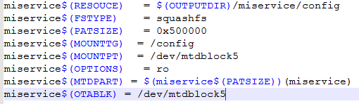
miservice$(RESOUCE)   = $(OUTPUTDIR)/miservice/config

miservice$(FSTYPE)    = ubifs

miservice$(PATSIZE)   = 0xA00000

miservice$(MOUNTTG)  = /config

miservice$(MOUNTPT)  = ubi0:miservice

miservice$(OPTIONS)   = rw
The ubifs partition does not need to add mtdpart information, that is, there is no need to add the partition location in cis$(SYSTAB)= xxx.
3.8. Add/Modify/Delete LFS Partition
The advantage of the Littlefs partition is that it can be accessed in uboot/linux/rtk.
The MISC partition is used to store files related to system configuration scripts, such as screen parameter information:
misc$(RESOUCE) = $(OUTPUTDIR)/misc
misc$(FSTYPE) = lfs
misc$(PATSIZE) = 0x60000
misc$(MOUNTTG) = /misc
misc$(MOUNTPT) = /dev/mtd4
misc$(OPTIONS) = rw
misc$(MTDPART) = $(misc$(PATSIZE))(MISC)
misc$(OTABLK) = /dev/mtdblock4
For modification methods, please refer to squashfs or jffs2.
3.9. Special Partition Processing
KERNEL, uboot, IPL, logo, cis, etc. are special partitions without special file systems and cannot be centrally processed in the Makefile script. Adding a special partition requires the following two steps (Take kernel partition as an example):
-
image.mkneeds partition and package script commands:kernel_nofsimage:
@echo [[$@]]

cp -rvf $($(patsubst %_nofsimage,%,$@)$(RESOUCE)) (IMAGEDIR)/$(patsubst %_nofsimage,%,$@)
-
script.mk needs the commands generated by the partition burning script:
kernel_$(FLASH_TYPE)__script:
@echo "# <- this is for comment / total file size must be less than 4KB" > $(SCRIPTDIR)/[[kernel.es
@echo tftp $(TFTPDOWNLOADADDR) kernel >> $(SCRIPTDIR)/[[kernel.es
@echo $(FLASH_PROBE) >> $(SCRIPTDIR)/[[kernel.es
@echo $(FLASH_ERASE_PART) KERNEL >> $(SCRIPTDIR)/[[kernel.es
@echo $(FLASH_WRITE_PART) $(TFTPDOWNLOADADDR) KERNEL \$${filesize} >> $(SCRIPTDIR)/[[kernel.es
@echo "% <- this is end of file symbol" >> $(SCRIPTDIR)/[[kernel.es
@echo kernel-image done!!!
4. ONE BIN
4.1. ONE BIN Partition
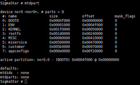
The ONE BIN function is based on the ALKAID packaging script to merge the BOOT PART partition into a bin through the dd command. From the perspective of uboot and linux kernel, you can enter the command mtdpart in uboot to see the current partition plan. The difference from pni is BOOT PART does not refine internal partitions, but consists of a BOOT partition.
-
NOR FLASH:
-
SPINAND FLASH:

After ONE BIN is packaged, a boot.bin will be generated under output/images/, which is spliced from the image of ipl/ipl_cust/uboot, and cis partition will be added to nor flash.
4.2. SPINAND BOOT Partition
On nand flash, BOOT0/BOOT1 belong to the A/B partition, and the ROM code is turned on from the BOOT0 partition by default. If an ECC ERROR occurs in the BOOT0 partition or an bad block is encountered, it will jump to the BOOT1 partition, and after the next boot, the default is from BOOT1 Open in the partition, which can ensure that a set of backup mechanism is established in the BOOT part during the upgrade process to avoid the inability to enter the UBOOT cmd line after the BOOT upgrade fails.
ONE BIN is spliced by the dd command, as shown below:
-
SPI-NAND:
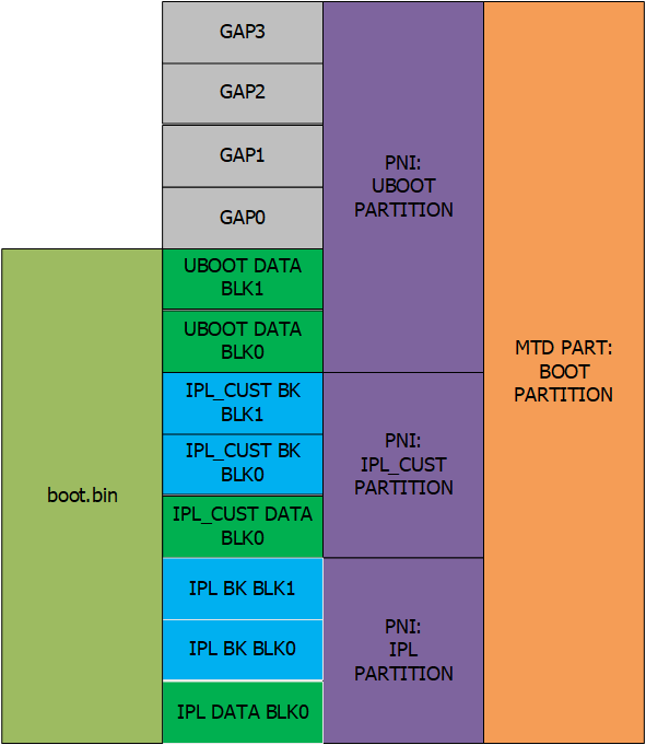
The orange part above represents the size of the partition in the MTD PART,
boot.binrepresents the actual one bin size, and the purple part represents the layout of this part in the PNI.The image of
IPL/IPL_CUSTdoes not exceed the size of one block, so they and their Backup each occupy the size of 3 blocks.UBOOT's data occupies the size of 2 blocks. Since uboot is often customized, the image size of uboot will change. Configuring 2 blocks cannot guarantee all situations. If you want to modify it, please modify the config file:
uboot$(DATASIZE) = 0x40000
4.3. SPINAND BOOT Partition Bad Block Processing
It is mandatory to reserve 4 BLOCK GAPs on UBOOT in order to make full use of the BK BLK of IPL and IPL_CUST (each has two backups). Mandatory reserved code:
uboot$(PATSIZE) = $(call sum, $(uboot$(DATASIZE)) $(call multiplyhex, $(FLASH_BLK_SIZE), 4))
The purpose of the reservation is to deal with bad blocks. It can be seen from the above that the BOOT partition of MTD PART is 4 blocks larger than the boot.bin to be burned. When using tftp or a burner to burn the code, if an bad block is encountered, the data will be automatically written to the next block, then the data after the current position will be shifted as a whole:
When an bad block occurs at the location of IPL_CUST DATA, it will be shown as follows after programming:

All data after IPL_CUST is shifted by one block, so will the data of uboot, and GAP will be occupied one block. In the absence of bad blocks, the entire boot partition allows a maximum of 4 bad blocks, which must satisfy that at least one block in the IPL/IPL_CUST partition is good. If there are more than 4 blocks or do not meet the above conditions, it will jump to the BOOT1 partition to ensure a smooth startup.
4.4. BL0 PBA/BL1 PBA Flag Bit Of SPINAND
Use SpiNandInfoEditor.exe to open flash.sni or flash_list.sni and you will see the following:
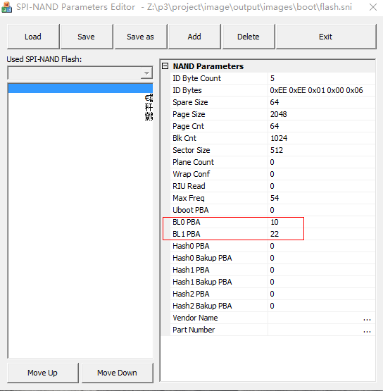
These are to find the IPL partition for rom code. The SNI file found in ALKAID/project/board is 0 by default, unit: block count, which means that the rom code find IPL0 and IPL1 from the default address (IPL0: 0x140000 , IPL1: 0x1A0000). It does not match the current partition configuration, so in the process of making cis.bin, a shell script will be used to fill in the BL0 PBA and BL1 PBA of flash.sni and flash_list.sni with the correct values, which corresponds to the block offset corresponding to the first address of the BOOT0/BOOT1 partition on the flash.
4.5. SPINOR BOOT Partition
SPINOR does not have A/B partition by default. The BOOT part is different from SPINAND. The BOOT partition of SPINOR includes CIS. The BOOT partition starts from address 0. The structure is as shown in the figure below.
SPINOR does not need to deal with bad blocks. IPL and IPL_CUTS do not have a backup block. The partitions in the boot part need to pay attention to the alignment of the first and last addresses of the partition and the partition size. The 4k alignment is to save space.
In boot, IPL/IPL_CUST/UBOOT/CIS partition first address and partition size must be a nor flash page (4k).The ENV partition is not in the BOOT partition, but it is required that its end address needs to be aligned with the size of a block of nor flash(generally 64k).
Then according to the layout in the figure below, there will be a GAP between UBOOT and ENV to ensure the alignment requirements, which is different from the role of spinand. In addition to ensuring the alignment requirements, it is also the buffer mechanism for the change of the data of UBOOT/IPL/IPL_CUS to cause the change of the internal partition of the PNI. The purpose is to ensure that even if the partition in the PNI changed, the BOOT partition and the env partition of the MTD remain unchanged.Reserve a larger amount of change when upgrading BOOT for ota (for ota upgrade, the partition cannot be changed).
The partition size of IPL/IPL_CUST/CIS/UBOOT in the NOR flash partition is automatically aligned to 4k in the script. Users only need to adjust the size of the MTD BOOT PARTITION to increase or decrease the GAP.
The BOOT size plus the ENV partition size must be aligned with the block size. The variables for setting the size are as follows:
boot$(PATSIZE) = 0x4F000

4.6. Note
If you need to modify the partition configuration of ONE BIN, please read this chapter carefully. Only uboot(DATASIZE) of spinand and boot and boot(PATSIZE)ofspinorcan be modified appropriately to deal with theIPL/IPL_CUS/UBOOT`image size changes, please check with FAE after modification.
If the modification is improper, it is easy to cause the BOOT in the production link to fail to start
If the packaging process does not refer to our company's ALKAID, pay special attention to the BL0 PBA and BL1 PBA in spinand's sni_list and gcis, you need to fill in the correct value according to the current BOOT0/BOOT1 position, or after confirming that the BOOT partition is normal, use the partition layout and boot.bin of BOOT compiled by ALKAID.
If you need to make boot.bin by yourself, please refer to the function updatecis of the Makefile in the script image.mk, and the target cis_nofsimage, boot_images.