I2C REFERENCE
1. Overview
Currently, the demo board supports 2 groups of I2C controllers.
2. Dts Config
2.1. Demo Board Supproted I2C Padmux
Table 1-1
| I2C Group | Mode | SCL | SDA | DEV |
|---|---|---|---|---|
| HW I2C group0 | 10 | PAD_KEY6 | PAD_KEY7 | /dev/i2c-0 |
| 11 | PAD_KEY12 | PAD_KEY13 | ||
| 12 | PAD_GPIO1 | PAD_GPIO2 | ||
| 13 | PAD_GPIO3 | PAD_GPIO4 | ||
| HW I2C group1 | 8 | PAD_KEY8 | PAD_KEY9 | /dev/i2c-1 |
| 9 | PAD_GPIO1 | PAD_GPIO2 |
Provide two groups of HW I2C:
The config of HW I2C group0 can choose one of the above 4 types, and the corresponding node is /dev/i2c-0; the config of HW I2C group1 can choose one of the above 2 types, and the corresponding node is /dev/i2c-1.
2.2. I2C Dts Config
I2C Dts Config take mode11 as an example.
-
i2c-padmux = \< Mode >, set the mode to 11, modify
pioneer3 -demo.dtsi.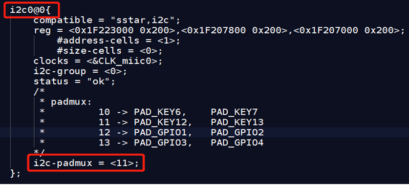
-
Add I2C0 padmux multiplexing
Modify
pioneer3-ssc020a-s01a-demo-padmux.dtsi.I2C0 selects Mode11 (PAD_KEY12/PAD_KEY13) for output. If it is not output in other groups, comment out these groups.

I2C Dts Config take mode8 as an example.
-
i2c-padmux = \< Mode>, set the mode to 8, modify
pioneer3 -demo.dtsi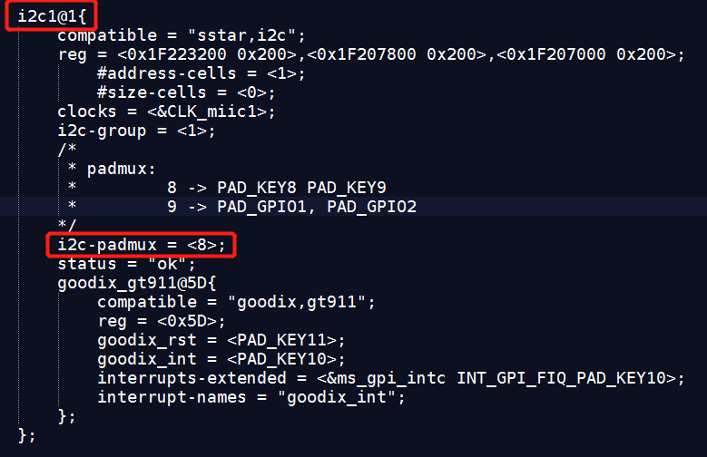
-
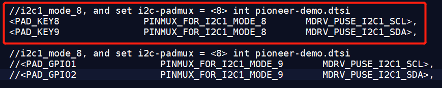
Add I2C1 padmux multiplexing
Modify
pioneer3-ssc020a-s01a-demo-padmux.dtsiI2C1 selects Mode8 (PAD_KEY8/PAD_KEY9) for output. If it is not output in other groups, comment out these groups.
3. Kernel Config
-
Open the kernel config for I2C
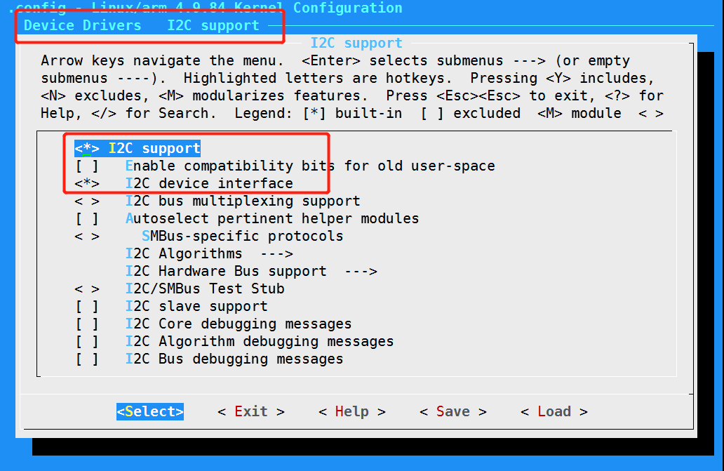
-
Open SStar I2C driver config

4. I2C Test
4.1. Check I2C PADMUX Config
Confirm the padmux config of I2C1 by reg in Uboot.

Use mode8, bit4~bit7 are 8.
Confirm the padmux config of I2C1 by reg in kernel.

The 16-bit address read in Kernel is 6f (de shifts one bit to the right), bit4~bit7 are 8, and the current mode is 8.
4.2. Verify I2C in Uboot
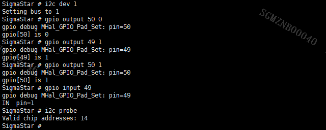
The I2C test cmd in Uboot is as follows, you can use i2c probe cmd to test whether the device is available.

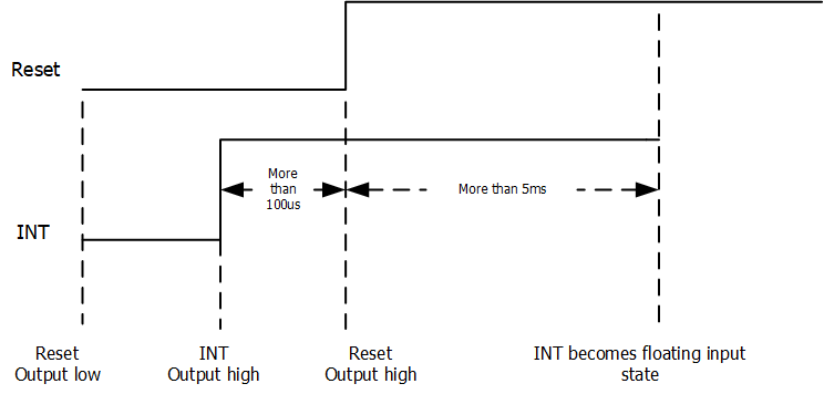
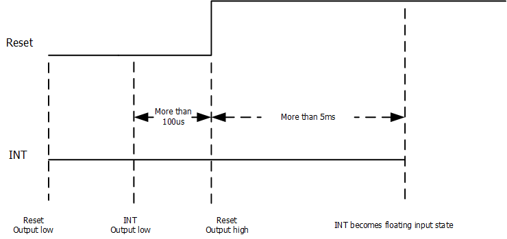
Probe devices in I2C bus1. There are two sets of slave addresses for gt911. The addresses are set by controlling Reset and INT during power-on initialization.
Slave address in Uboot is 0x14.
Slave address in Uboot is 0x5D.
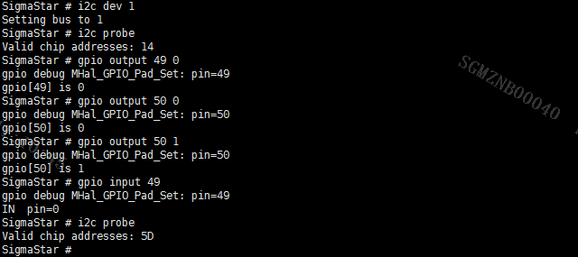
Please use 0x5D in kernel。
4.3. Verify I2C in Kernel
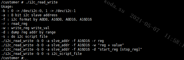
Use i2c_read_write to verify, the test commands are as follows.
Write 0x40 to reg 0x8140 whose slave addr is 0xba (0x5d shifted one bit to the left).
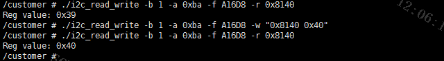
Read the data bit 0x39 for the first time. After writing 0x40, read the data again, and the result is consistent with the written data.
5. Demo
5.1. Kernel Demo
Test code: testI2c.c
Take i2c read and write sensor as an example:
-
Compile the code to generate a test bin.
arm-linux-gnueabihf-gcc –o testI2c testI2c.c -
Mount it to the board, run the sensor-related demo (such as zkgui's Face Detection), and initialize the sensor.
-
Run test bin file
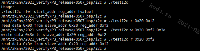
0x20 is the sensor device address, and 0xf2 is a readable and writable register address of the sensor. Write data to the register and then read it out, which is consistent with the write.
-
Compare with the read and write results of the i2c_read_write tool (0x20 shifted one bit to the left).
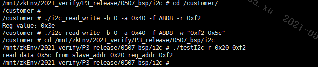
Use the test bin file to write, and use i2c_read_write to read, the results are consistent;
Use i2c_read_write to write, and use the test bin file to read, the results are consistent.
The demo reads and writes i2c normally.