SDK Module Debugging Manual
1. Overview
Linux's porc file system can print out the current running status of each module, which is convenient for debugging and analyzing. Each module has a specific path, and some modules have echo commands.
Path: /proc/mi_modules
Table 1-1 File list
| Module name | Description |
|---|---|
| SYS | SYS module info |
| AI | Audio input info |
| AO | Audio output info |
| VIF | Video input info |
| VPE | Video processing engine info |
| VENC | Video encoding info |
| DIVP | De-interlacing/image engine info |
| VDISP | Virtual display module info |
| DISP | Display module info |
| HDMI | HDMI info |
| FB | Graphic layer info |
| GFX | Graphic engine info |
| REGION | OSD info |
| VDEC | Video decoding info |
2. SYS
2.1. Common
2.1.1. dump_mmap
-
Debug info
# ./config/dump_mmap
Fig 2-1
-
Debug info analysis
The configured API is stored under Common, the purpose is as follows:
-
Do iniparser in user mode without entering the kernel.
-
It is convenient to confirm the content of the config file during debugging, and avoid the deviation between the content printed in the parser and the actual setting.
The files imported into config are as follows:
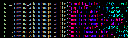
Fig 2-2
Write the struct parsed in
Systeminfo.cinto config_info.Write the struct parsed in
Pqloader.cinto pq_info and *_table, where the table is a continuous memory placement, and MISDK is an indirect array pointing to a one-dimensional array.The config files imported into mmap are as follows:

Fig 2-3
Write the parsed struct in
Mmapinfo.cinto mmap_info and memory_info. Because this is relatively simple, the info read from mmap_info and memory_info are formatted and readable. -
2.1.2. dump_config
-
Debug info
# ./config/dump_config

panel size:24
DBC Value=
        55,30,10
        254,66,0
        72,80,72
start dump [motion_table](6, 8)
{0xe8,0xcd,0xab,0x89,0x67,0x45,0x23,0x00,}
{0xd8,0xbc,0x9a,0x78,0x56,0x34,0x12,0x00,}
{0xc8,0xab,0x89,0x67,0x45,0x23,0x01,0x00,}
{0xb8,0x9a,0x78,0x56,0x34,0x12,0x00,0x00,}
{0xa8,0x89,0x67,0x45,0x23,0x01,0x00,0x00,}
{0x98,0x78,0x56,0x34,0x12,0x00,0x00,0x00,}
end dump
start dump [motion_hdmi_dtv_table](4, 8)
{0x68,0x45,0x23,0x01,0x00,0x00,0x00,0x00,}
{0xa8,0x89,0x67,0x45,0x23,0x01,0x00,0x00,}
{0xc8,0xab,0x89,0x67,0x45,0x23,0x01,0x00,}
{0xe8,0xcd,0xab,0x89,0x67,0x45,0x23,0x00,}
end dump
start dump [motion_comp_pc_table](4, 8)
{0x68,0x45,0x23,0x01,0x00,0x00,0x00,0x00,}
{0x98,0x78,0x56,0x34,0x12,0x01,0x00,0x00,}
{0xa8,0x89,0x67,0x45,0x23,0x12,0x01,0x00,}
{0xb8,0x9a,0x78,0x56,0x34,0x12,0x01,0x00,}
end dump
start dump [misc_param_table](4, 4)
{0x02,0xff,0x00,0x00,}
{0x02,0xff,0x01,0x66,}
{0x03,0x88,0x01,0x66,}
{0x03,0xaa,0x01,0x66,}
end dump
start dump [misc_luma_table](8, 2)
{0x33,0x08,}
{0x33,0x07,}
{0x22,0x06,}
{0x22,0x05,}
{0x11,0x04,}
{0x11,0x03,}
{0x00,0x02,}
{0x00,0x01,}
end dump
start dump [noise_table](6, 8)
{0x67,0x45,0x34,0x23,0x12,0x01,0x00,0x00,}
{0xab,0x89,0x67,0x45,0x23,0x12,0x01,0x00,}
{0xbc,0x9a,0x78,0x56,0x34,0x23,0x01,0x00,}
{0xde,0xbc,0x9a,0x78,0x56,0x34,0x12,0x00,}
{0xef,0xcd,0xab,0x89,0x67,0x45,0x23,0x00,}
{0x00,0x00,0x00,0x00,0x00,0x00,0x00,0x00,}
end dump
start dump [misc_table](6, 15)
{0x00,0x00,0x00,0x00,0x00,0x02,0x00,0x00,0x02,0x00,0xc0,0x9f,0x00,0x01,0x66,}
{0x10,0x01,0xc1,0xc1,0xc1,0x04,0x09,0x1f,0x03,0x88,0xc0,0x9f,0x00,0x01,0x66,}
{0x21,0x02,0xc2,0xc2,0xc2,0x08,0x09,0x1f,0x03,0x99,0x00,0x00,0x00,0x01,0x88,}
{0x31,0x04,0xc2,0xc2,0xc2,0x0a,0x09,0x1f,0x03,0xaa,0x00,0x00,0x00,0x01,0xaa,}
{0x41,0x06,0xc3,0xc3,0xc3,0x10,0x19,0x1f,0x03,0xbb,0x00,0x00,0x14,0x01,0xbb,}
{0x00,0x00,0x00,0x00,0x00,0x00,0x00,0x00,0x00,0x00,0x00,0x00,0x00,0x00,0x00,}
end dump
-
Debug info analysis
./config/dump_config gets the information of each file in /proc/mi_modules/common/, including panel size, DBC Value, motion_table, motion_hdmi_dtv_table, motion_comp_pc_table, misc_param_table, misc_luma_table, noise_table, misc_table, etc.
2.2. mi_log_info
2.2.1. cat
-
Debug info
# cat /proc/mi_modules/mi_log_info

---------------- Log Path ------------------------
log path:
---------------- Store Path ----------------------
store path:  /mnt
---------------- Module Log Level ----------------
Log module        Level
--------------------------
mi_ive            2(WRN)
mi_vdf            2(WRN)
mi_venc           2(WRN)
mi_rgn            2(WRN)
mi_ai             2(WRN)
mi_ao             2(WRN)
mi_vif            2(WRN)
mi_vpe            2(WRN)
mi_vdec           2(WRN)
mi_sys            2(WRN)
mi_fb             2(WRN)
mi_hdmi           2(WRN)
mi_divp           2(WRN)
mi_gfx            2(WRN)
mi_vdisp          2(WRN)
mi_disp           2(WRN)
mi_os             2(WRN)
mi_iae            2(WRN)
mi_md             2(WRN)
mi_od             2(WRN)
mi_shadow         2(WRN)
-
Debug info analysis
It shows the default
log pathorstore path, and the debug_level value of each module. -
Parameter analysis
Table 2-1
Parameter Description mi_log_info log path No effect store path No effect Log module Modules name Level Print level
2.2.2. echo
Table 2-2
| Function | Modify the debug_level |
|---|---|
| Command | echo [ModID]=[Level] > /proc/mi_modules/mi_log_info |
| [ModID] Module name mi_ive/ mi_vdf /mi_venc /mi_rgn /mi_ai /mi_ao /mi_vif /mi_vpe /mi_vdec /mi_sys/ mi_fb /mi_hdmi /mi_divp /mi_gfx /mi_vdisp /mi_disp/ mi_os /mi_iae /mi_md /mi_od /mi_shadow | |
| Parameter description | [Level] 0: No debug info 1: Only display error info (MI_DBG_ERR) 2: Only display waring info (MI_DBG_WRN) 3: Only display info (MI_DBG_INFO) 4 : Display all info |
| Example | echo mi_sys=2 > /proc/mi_modules/mi_log_info ; Modify the debug_level of mi_sys to 2 |
Table 2-3
| Function | Modify the path of log |
|---|---|
| Command | echo log=[Path] > /proc/mi_modules/mi_log_info |
| Parameter description | [Path] Path |
| Example | echo log=/mnt > /proc/mi_modules/mi_log_info |
Table 2-4
| Function | Modify the path of log storage |
|---|---|
| Command | echo storepath=[Path] > /proc/mi_modules/mi_log_info |
| Parameter description | [Path] Path |
| Example | echo storepath=/mnt > /proc/mi_modules/mi_log_info |
2.3. mi_global_info
2.3.1. cat
-
Debug info
# cat /proc/mi_modules/mi_global_info

miu_and_lx_info:
ARM_MIU0_BUS_BASE 0x20000000        ARM_MIU0_BASE_ADDR 0x0
ARM_MIU1_BUS_BASE 0x60000000        ARM_MIU1_BASE_ADDR 0x80000000
ARM_MIU2_BUS_BASE 0xffffffff            ARM_MIU2_BASE_ADDR 0xffffffff
lx_mem_addr  0x20c00000         lx_mem_size  0xe300000
lx_mem2_addr 0xffffffff             lx_mem2_size 0xffffffff
lx_mem3_addr 0xffffffff             lx_mem3_size 0xffffffff

KernelProtect IP white list:
clientId    name
            43                   MIU_CLIENT_MIPS_RW
            50                   MIU_CLIENT_NAND_RW
            82              MIU_CLIENT_USB_UHC0_RW
            83              MIU_CLIENT_USB_UHC1_RW
            84              MIU_CLIENT_USB_UHC2_RW
            18                    MIU_CLIENT_G3D_RW
        140                   MIU_CLIENT_USB3_RW
        129                   MIU_CLIENT_SDIO_RW
        165                   MIU_CLIENT_SATA_RW
        133              MIU_CLIENT_USB_UHC3_RW
        225               MIU_CLIENT_USB30_1_RW
        226               MIU_CLIENT_USB30_2_RW
            5                   MIU_CLIENT_BDMA_RW
            14                   MIU_CLIENT_EMAC_RW

PAGE_OFFSET - the virtual address of the start of the kernel image
PAGE_OFFSET=0xc0000000
TASK_SIZE - the maximum size of a user space task
TASK_SIZE=0xbf000000
MStar SDK version: commit.build_time 0be783c.2017121315
CHIP_VERSION  U02
-
Debug info analysis
It provides some global information.
-
Parameter analysis
Table 2-5
Parameter Description miu_and_lx_info(Take MIU(which have only one) as an example) ARM_MIU0_BUS_BASE Miu0 bus base ARM_MIU0_BASE_ADDR Miu0 base addr lx_mem_addr The starting address of the memory occupied by the Linux image(Belongs to cpu bus address) lx_mem_size The memory size occupied by the Linux image kernelProtect IP white list clientId The ID in the Miu protect IP whitelist (It is a global ID when it is not grouped) name IP name corresponding to clientId MStar SDK version: commit.build_time commit Commit corresponding to SDK build_time SDK build time CHIP_VERSION CHIP_VERSION Current chip version, version number: U01, U02, U03...
2.4. mi_bufqueue_status
2.4.1. cat
-
Debug info
# cat /proc/mi_modules/mi_bufqueue_status

dump Queues in input port only for enabled port:

ModId DevId ChnId PassId InPortId UsrInjectQ_cnt BindInQ_cnt

12 0 0 0 0 0 0 0

dump Queues in output port only for enabled port:

ModId DevId ChnId PassId OutPortId DrvBkRefFifoQ_cnt DrvBkRefFifoQ_size
UsrGetFifoQ_cnt

12 0 0 0 0 0 0 0 0
-
Debug info analysis
Dump the queue information related to the enabled input/output port of the current modules.
-
Parameter analysis
Table 2‑6
Parameter Description dump Queues in input port(only dump enabled Input port) ModId input port's module id DevId input port's device id ChnId input port's channel id PassId input port's pass id InPortId input port's id UsrInjectQ_cnt UsrInjectBufQueue buff's total size of inputPort BindInQ_cnt UsrPipeInBufQueue buff's total size of inputPort InputPendingQueueSize WorkingQueue buff's total size of inputPort dump Queues in output port(only dump enabled output port) ModId output port's module id DevId output port's device id ChnId output port's channel id PassId output port's pass id OutPortId output port's id DrvBkRefFifoQ_cnt DrvBkRefFifoQueue buffer's total size of outputPort DrvBkRefFifoQ_size DrvBkRefFifoQueue buffer's total size of outputPort UsrGetFifoQ_cnt UsrGetFifoBufQueue buffer's total size of outputPort
2.5. debug_level
2.5.1. cat/echo
-
Debug info
# cat /proc/mi_modules/mi_sys/debug_level 2 -
Debug info analysis
In order to control the printing level, each module (including sys) has its own debug level, which is controlled by /proc/mi_modules/mi_modulename/debug_level, where disp, divp, rgn, etc. are modulenames. Take /proc/mi_modules/mi_sys/debug_level as an example.
Table 2‑7
Function Print warning level Command cat /proc/mi_modules/[ModuleName]/debug_level Parameter description [ModuleName] Module name
mi_disp mi_gfx mi_rgn mi_vdec mi_vpe mi_ai mi_divp mi_shadow mi_vdisp mi_ao mi_hdmi mi_sys mi_venc mi_bar mi_vifExample cat /proc/mi_modules/mi_sys/debug_level 2
The warning level of mi_sys is 2(Only display waring info)Table 2‑8
Function Modify warning level Command echo [Level] > /proc/mi_modules/[ModuleName]/debug_level Parameter description [Level] 0 No debug info 1 Only display error info (MI_DBG_ERR) 2 Only display waring info (MI_DBG_WRN) 3 Only display info (MI_DBG_INFO) 4 Display all info [ModuleName] Module name
mi_disp / mi_gfx / mi_rgn / mi_vdec / mi_vpe / mi_ai / mi_divp / mi_shadow / mi_vdisp / mi_ao / mi_hdmi / mi_sys / mi_venc / mi_bar / mi_vifExample echo 1 > /proc/mi_modules/mi_vdec/debug_level
Modify the warning level of the mi_vdec module to only display error info
2.6. miu_protect
2.6.1. cat
-
Debug info
cat /proc/mi_modules/mi_sys_mma/miu_protect

=================== start miu_protect_info ================================

kernel protect enabled

LX :

cpu_start_addr:0x20c00000 size:0xe300000

miu_index miuBlockIndex start_cpu_bus_pa length

0x0 0x00 0x20c00000 0x460000

KernelProtect IP white list:

clientId name

43 MIU_CLIENT_MIPS_RW

50 MIU_CLIENT_NAND_RW

82 MIU_CLIENT_USB_UHC0_RW

83 MIU_CLIENT_USB_UHC1_RW

84 MIU_CLIENT_USB_UHC2_RW

18 MIU_CLIENT_G3D_RW

140 MIU_CLIENT_USB3_RW

129 MIU_CLIENT_SDIO_RW

165 MIU_CLIENT_SATA_RW

133 MIU_CLIENT_USB_UHC3_RW

225 MIU_CLIENT_USB30_1_RW

226 MIU_CLIENT_USB30_2_RW

5 MIU_CLIENT_BDMA_RW

14 MIU_CLIENT_EMAC_RW
-
Debug info analysis
It shows info related to miu protect.
-
Parameter analysis
Table 2‑9
Parameter Description kernel protect Enabled kernel protect or not, enabled by default. LX (take only one LX as an example, LX is the memory corresponding to the linux mirror) cpu_start_addr Start CPU addr corresponding to LX. size The size corresponding to LX. Information about the range of a kernel protect miu_index serial number. miuBlockIndex Number information of 4 miu ranges. start_cpu_bus_pa The starting cpu bus addr of the range. length The length of range. KernelProtect IP white list clientId The ID in the Miu protect IP whitelist (It is a global ID when it is not grouped) name IP name corresponding to clientId
2.7. mma_help_name
2.7.1. cat
-
Debug info
# cat /proc/mi_modules/mi_sys_mma/mma_heap_name0

mma heap name heap_base_cpu_bus_addr length chunk_mgr_avail

mma_heap_name0 25200000 9d00000 79c6000

chunk_mgr info:

pst_chunk_mgr offset length avail

c3545618 0 9d00000 79c6000

each chunk info:

offset length used_flag task_name

0 1000 1 insmod

1000 100000 1 insmod

101000 200000 1 proc_rtsp

301000 3f5000 1 vdisp-dev0

6f6000 3f5000 1 vdisp-dev0

aeb000 3f5000 1 vdisp-dev0

ee0000 1f5000 0 NA

10d5000 1000 1 proc_rtsp

10d6000 64000 1 proc_rtsp

113a000 200000 1 proc_rtsp

133a000 700000 1 proc_rtsp

1a3a000 3f5000 0 NA

1e2f000 3f5000 1 vdisp-dev0

2224000 700000 1 proc_rtsp

2924000 73dc000 NA
-
Debug info analysis
The cat information corresponds to the basic information and current state of the mma heap.
-
Parameter analysis
Table 2‑10
Parameter Description heap basic info mma heap name mma heap name heap_base_cpu_bus_addr The starting cpu bus addr of the heap length length of heap The reminding memory in heap chunk_mgr_avail chunk_mgr info pst_chunk_mgr The value of the chunk mgr pointer offset chunk mgr offset. The entire mma heap is used as a chunk mgr, so the value is always 0. length chunk mgr length. The entire mma heap is used as a chunk mgr, so the value is always mma heap length avail The remaining memory in chunk mgr (heap) each chunk info (Information and usage of each chunk in chunk mgr) offset The offset of the chunk in chunk mgr length length of chunk used_flag Whether the chunk is allocated. If yes, the value is 1; otherwise, it is 0 task_name If the used flag is 1, the task stored in task_name uses it; otherwise, the value is invalid
2.7.2. echo
Table 2‑11
| Function | Dump offset and length data to the specified path |
|---|---|
| Command | echo [Path] [Offset] [Length] > /proc/mi_modules/mi_sys_mma/mma_heap_name[Num] |
| Parameter description | [Path] The path to save the file, only need to provide the path, the system will automatically generate the corresponding file name according to the parameters. [Offset] Dump data from the offset of the mma heap, which must be aligned with 4KB. [Length] The amount of dumped data in the mma heap, which must be 4KB aligned. [Num] The number corresponding to mma head, mma_heap_name0 can be viewed through cat /proc/cmdline |
| Example | echo /mnt/ 0 4096 > /proc/mi_modules/mi_sys_mma/mma_heap_name0 Generated mma__mma_heap_name0__0__4096.bin in /mnt |
2.8. imi_mma_heap
2.8.1. cat
-
Debug info
# cat /proc/mi_modules/mi_sys_mma/imi_mma_heap

mma heap name heap_base_cpu_bus_addr length chunk_mgr_avail mmuEnable

mma_heap_name0 22000000 1f80000 1c8a000 1

chunk_mgr info:

offset length avail

0 10000000 fd0a000

each chunk info:

offset length used_flag task_name pid Module

0 20000 0 NA -1 mi_sys
-
Debug info analysis
The cat information corresponds to the basic information and current state of the mma heap.
-
Parameter analysis
Table 2‑12
Parameter Description heap basic info mma heap name mma heap的name heap_base_cpu_bus_addr The starting cpu bus addr of the heap length length of heap chunk_mgr_avail The remaining memory in heap mmuEnable Mma heap support HW_MMU or not. 1 is support, 0 is not. chunk_mgr info offset chunk mgr offset, the entire mma heap is used as a chunk mgr, so the value is always 0 length chunk mgr length, the entire mma heap is used as a chunk mgr, so the value is always mma heap length avail The remaining memory in chunk mgr (heap) each chunk info (Information and usage of each chunk in chunk mgr) offset The offset of the chunk in chunk mgr length length of chunk used_flag Whether the chunk is allocated. If yes, the value is 1; otherwise, it is 0 task_name If the used flag is 1, the task stored in task_name uses it; otherwise, the value is invalid pid Current->tgid to which the chunk belongs Module The module to which the chunk belongs
2.9. vb_pool_qlobal
2.9.1. cat
-
Debug info
# cat /proc/mi_modules/mi_sys_mma/vb_pool_global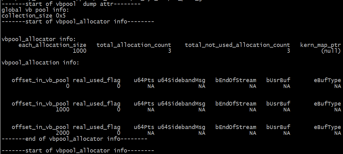
Fig 2‑4
-
Debug info analysis
If global public pools are configured through MI_SYS_IMPL_ConfGloPubPools API or MI_SYS_ConfGloPubPools API, there is a /proc/mi_modules/mi_sys_mma/vb_pool_global file; otherwise, there is no such file.
-
Debug info analysis
Table 2‑13
Parameter Description collection_size The number of allocators in the pool One of the info of vbpool_allocators each_allocation_size The allocation size in the allocator (different allocation sizes of the same vbpool allocator are the same, and different allocation sizes of different allocators in the same pool may be different) total_allocation_count The number of allocations in the allocator total_not_used_allocation_count The unused number of allocations in the allocator kern_map_ptr The kernel space va of the allocator offset0; if not, the value is NULL A vbpool_allocation info of the specified vbpool_allocator offset_in_vb_pool The logical offset allocation in the corresponding allocator real_used_flag Whether it is being used, if not, the subsequent parameters are invalid u64Pts If it is valid, the value is pts. u64SidebandMsg If it is valid, the value is SidebandMsg bEndOfStream If it is valid, the value indicates whether it is the flag of end stream bUsrBuf If it is valid, the value indicates whether it is UsrBuf eBufType If it is valid, the value is buf type
2.9.2. echo
Table 2‑14
| Function | Dump offset and length data to the specified path |
|---|---|
| Command | echo [Path] [Offset] [Length] > /proc/mi_modules/mi_sys_mma/ vb_pool_global |
| Parameter description | [Path] The path to save the file, only need to provide the path, the system will automatically generate the corresponding file name according to the parameters. [Offset] Logical offset of pools, dump data from an offset of pools [Length] The amount of data dumped in the pools. |
| Example | / # echo /mnt/ 0 1024 > /proc/mi_modules/mi_sys_mma/vb_pool_global; Generate vb_pool__global__0__1024.bin in /mnt |
2.10. vb_pool
2.10.1. cat
-
Debug info
# cat /proc/mi_modules/mi_sys_mma/vb_pool_mi_divp0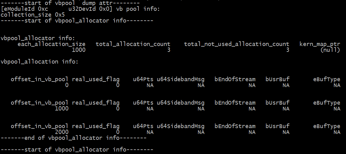
Fig 2‑5
-
Debug info analysis
Configure a device's vb pool to generate /proc/mi_modules/mi_sys_mma/vb_pool_modnamedevid file, (modname, such as dipp, vpe, etc., devid, such as 0,1, etc.) It corresponds to the device, and vb_pool_global corresponds to the global shared vb pool.
Taking vb_pool_mi_divp0 as an example, the cat command displays various information, and only "echo path offset length >" is used to dump data. Both of these are similar to vb_pool_global.
2.10.2. echo
Table 2‑15
| Function | Dump offset and length data to the specified path |
|---|---|
| Command | echo [Path] [Offset] [Length] > /proc/mi_modules/mi_sys_mma/[ModID] |
| Parameter description | [Path] The path to save the file, only need to provide the path, the system will automatically generate the corresponding file name according to the parameters. [Offset] Logical offset of pools, dump data from an offset of pools [Length] The amount of data dumped in the pools. [ModID] File name of vb_pool, such as vb_pool_mi_divp0 |
| Example | echo /mnt/ 0 4096 > /proc/mi_modules/mi_sys_mma/vb_pool_mi_divp0 ; Generate vb_pool__mi_divp0__0__4096.bin in /mnt/ |
2.11. meta
2.11.1. cat
-
Debug info
# cat /proc/mi_modules/mi_sys_mma/meta

=================== start meta_info ================================

basic info:

total page count:16 each meta data size:256 total_count_with_metadatasize 256
total_free_count_with_metadatasize:254

meta info :

ref_cnt=3

each allocation info:

offset_in_pool length phy_addr va_in_kern real_used_flag

0x0 0x100 0x2336000 c1736000 0

0x100 0x100 0x2336100 c1736100 0

0x200 0x100 0x2336200 c1736200 0

0x300 0x100 0x2336300 c1736300 0

0x400 0x100 0x2336400 c1736400 0

0x500 0x100 0x2336500 c1736500 0

0x600 0x100 0x2336600 c1736600 0

0x700 0x100 0x2336700 c1736700 0

0x800 0x100 0x2336800 c1736800 0

0x900 0x100 0x2336900 c1736900 0

0xa00 0x100 0x2336a00 c1736a00 0

……

=================== end meta_info ================================
-
Debug info analysis
After using the meta allocator (only one), /proc/mi_modules/mi_sys_mma/meta will be generated, and the corresponding memory will be completely allocated and waiting to be used.
2.11.2. echo
Table 2‑16
| Function | Dump offset and length data to the specified path |
|---|---|
| Command | echo [Path] [Offset] [Length] > /proc/mi_modules/mi_sys_mma/ vb_pool_global |
| Parameter description | [Path] The path to save the file, only need to provide the path, the system will automatically generate the corresponding file name according to the parameters. [Offset] Logical offset of allocator. dump data from an offset of an offset. [Length] The amount of data dumped in the allocator. |
| Example | echo /mt 0 1024 > /proc/mi_modules/mi_sys_mma/meta; Generate meta__0__1024.bin in /mnt |
2.12. mi_modulenamedevid
2.12.1. cat
-
Debug info
cat /proc/mi_modules/mi_disp/mi_disp0
Fig 2‑6
-
Debug info analysis
The result of the cat operation:
-
Provide general debugging information for the device from the device, channel, input port, and output port of MI_SYS,
-
The private information of the device, which is provided by each module.
Take cat /proc/mi_modules/mi_vdisp/mi_vdisp0 as an example. The result is as above.
-
-
Parameter
Table 2‑17
Parameter Description Common info for device ChnNum The device channel number EnChnNum The device enabled channel number InPortNum The device input ports number OutPortNum The device output ports number CollectSize The allocators number in allocatorCollection corresponding to dev Common info for channel(only dump enabled channel) ChnId Channel id EnInPNum channel enabled input ports number EnOutPNum channel enabled output ports number MMAHeapName If SetChnMMAConf is set, the value is the corresponding mma heap name; if not, the value is NULL Input port common info(only dump enabled Input port) ChnId channel id of the input port PortId id of the input port SrcFrmrate Src frame rate DstFrmrate Dst frame rate user_buf_quota Quota of the inputPort buffs number UsrInjectQ_cnt The buffs number of UsrInjectBufQueue in InputPort UsrInjectQ_size The buffs size of UsrInjectBufQueue in InputPort BindInQ_cnt The buffs number of BindInputBufQueue in InputPort BindInQ_size The buffs size of BindInputBufQueue in InputPort WorkingQ_cnt The buffs number of WorkingQueue in InputPort WorkingQ_size The buffs size of the WorkingQueue in the InputPort usrLockedInjectCnt The buf currently owned by the user Input port bind info(only dump enabled Input port) ChnId Channel id of the input port PortId id of the input port bind_module_id The module id of the output port bound to the input port bind_module_name The module name of the output port bound to the input port bind_ChnId The channel id of the output port bound to the input port bind_PortId The output port id bound to the input port Output port common info (only dump enabled Output port) ChnId The channel id of output port PortId The output port id BufCntQuota Quota of the OutputPort buff number usrLockedCnt The buffer taken by the user from UsrGetFifoBufQueue totalOutPortInUsed totalOutputPortInUsedBuf number DrvBkRefFifoQ_cnt The buffer number in the OutputPort DrvBkRefFifoQueue DrvBkRefFifoQ_size The buffer size in the OutputPort DrvBkRefFifoQueue UsrGetFifoQ_cnt The buffer number in the OutputPort UsrGetFifoBufQueue UsrGetFifoQ_size The buffer size in the OutputPort UsrGetFifoBufQueue WorkingQ_cnt The buffer number in the OutputPort WorkingQueue WorkingQ_size The buffer size in the OutputPort WorkingQueue Output port BindPeerInputPortList info(only dump enabled Output port) ChnId channel's output port id PortId output port id bind_module_id The module id of the input port bound to the output port bind_module_name The module name of the bound input port bind_ChnId The channel id of the bound input port bind_PortId Bound input port id
2.12.2. echo
Table 2‑18
| Function | Get the module help info |
|---|---|
| Command | echo help > /proc/mi_modules/[ModName]/[ModID] |
| Parameter description | [ModName] Module name mi_disp / mi_gfx / mi_rgn / mi_vdec / mi_vpe / mi_ai / mi_divp / mi_shadow / mi_vdisp / mi_ao / mi_hdmi / mi_sys / mi_venc / mi_bar / mi_vif [ModID] The corresponding file in the module. Format: Module name + number Such as mi_disp0 / mi_gfx0 / mi_rgn0 |
| Example | echo help > /proc/mi_modules/mi_disp/mi_disp0; Get the help info of the mi_disp0 node file |
Table 2‑19
| Function | Dump Port info |
|---|---|
| Command | echo dump_buffer [ChnID] [PortType] [PortID] [QueueName][Path] [EndMethod] > /proc/mi_modules/[ModName]/[ModID] |
| Parameter description | [ChnID] Channel ID [PortType] iport: input port; oport: output port [PortID] port id [QueueName] The value of input port is "UsrInject" or "BindInput", and the value of output port is "UsrGetFifo" [Path] File path where data is saved. Note that it is an absolute path, the system will automatically generate the file name according to the parameters, and different buffers are stored in different files. [EndMethod] End method of dump buffer. Only three types are supported: (1). "bufnum=xxx":dump the specified number of buffers (2) "time=xxx"(unit: ms):dump continuous time (3) . "start/end" pair: start dump with start and end dump with end. When using start/end, the other 5 parameters must be exactly the same. [ModName] Module name mi_disp / mi_gfx / mi_rgn / mi_vdec / mi_vpe / mi_ai / mi_divp / mi_shadow / mi_vdisp / mi_ao / mi_hdmi / mi_sys / mi_venc / mi_bar / mi_vif [ModID] The corresponding file in the module. Format: Module name + number |
| Example | echo dump_buffer 0 iport 0 BindInput /mnt bufnum=1 > /proc/mi_modules/mi_disp/mi_disp0 ; dump disp module iport data |
2.13. mi_dump_buffer_delay_worker
2.13.1. cat
-
Debug info
cat /proc/mi_modules/mi_dump_buffer_delay_worker

delay_worker_id module_name force_stop dev_id chn_id port_type port_id

0 mi_disp 0 0 0 inport 0

Queue_name stored_dir dump_method dump_method_value

BindInput /mnt bunfnum 2
-
Debug info analysis
/proc/mi_modules/mi_dump_buffer_delay_workeris a concept connected to mi_modulenamedevid. The buffer in the device Queue is dumped through delay worker, and cat mi_dump_buffer_delay_worker to view the delay worker in progress. The echo force_stop_dump delay_worker_id is forcibly ending a specified delay worker. -
Parameter
Table 2‑20
Parameter Description delay_worker_id delay worker id. After the delay worker is completed, the id will be recycled and used by other delay workers. module_name The module id corresponding to the delay worker. force_stop Whether the delay worker is in the forced end phase. 1: Yes, 0: No. dev_id The device id corresponding to the delay worker. chn_id The channel id corresponding to the delay worker. port_type The port type corresponding to the delay worker. input port or output port port_id The port id corresponding to the delay worker. Queue_name The Queue name corresponding to the delay worker. stored_dir The absolute storage path of the data to be dumped by the delay worker (excluding the file name of the final storage) dump_method dump delay worker: bufnum, or time, or start dump_method_value The value of the Dump method.
2.13.2. echo
Table 2‑21
| Function | Forced end the delay worker |
|---|---|
| Command | echo force_stop_dump [WorkID] >/proc/mi_modules/mi_dump_buffer_delay_worker |
| Parameter description | [WorkID] delay_work ID |
| Example | echo force_stop_dump 0 > /proc/mi_modules/mi_dump_buffer_delay_worker; Forced stop delay_work 0 |
2.14. module version
2.14.1. cat
-
Debug info
# cat /proc/mi_modules/mi_ai/module_version_file

MStar Module version: project_commit.sdk_commit.build_time
c1799df.fd2d52b.20171225180033

# cat /proc/mi_modules/mi_global_info

…..

MStar Module version: project_commit.sdk_commit.build_time
cb68bfd.44aca45.20171226100257

…..
-
Debug info analysis
xxxx_version_file provides version information, so does the
/proc/mi_modules/mi_global_info.The version info is about mi_sys module, the above is taking mi_vi and mi_global_info as examples, each module has their version file.
-
Parameter
Table 2‑22
Parameter Description Version Info project_commit The whole package project commit when the module compiles ko. Replace ko, the commit changes, the commit obtained in the ko version will also change. sdk_commit The whole sdk commit when the module compiles ko. Replace ko, the commit changes, the commit obtained in the ko version will also change. build_time build time. Accurate to the second, make clean; make image build as a whole, and the time of each ko is also different.
2.15. show threads
2.15.1. echo
-
Debug info
# echo show_threads > /proc/mi_modules/mi_sys/mi_sys0

<3>printk in _MI_SYS_IMPL_Common_WriteProc

<6>  task                PC stack   pid father

<6>busybox         S    1      0 0x00000000

<3>[<c01d3a6f>] (__schedule) from [<c01d3bb7>] (schedule+0x57/0x64)

<3>[<c01d3bb7>] (schedule) from [<c001bfbd>] (do_wait+0xed/0x134)

<3>[<c001bfbd>] (do_wait) from [<c001c367>] (SyS_wait4+0x69/0x7e)

<3>[<c001c367>] (SyS_wait4) from [<c000d2a1>] (ret_fast_syscall+0x1/0x54)

<6>kthreadd        S    2      0 0x00000000

<3>[<c01d3a6f>] (__schedule) from [<c01d3bb7>] (schedule+0x57/0x64)

<3>[<c01d3bb7>] (schedule) from [<c002b077>] (kthreadd+0x6d/0xf6)

<3>[<c002b077>] (kthreadd) from [<c000d381>] (ret_from_fork+0x11/0x30)

<6>ksoftirqd/0     S    3      2 0x00000000

<3>[<c01d3a6f>] (__schedule) from [<c01d3bb7>] (schedule+0x57/0x64)

<3>[<c01d3bb7>] (schedule) from [<c002c9af>] (smpboot_thread_fn+0xff/0x12c)

<3>[<c002c9af>] (smpboot_thread_fn) from [<c002a911>] (kthread+0xa1/0xb4)

<3>[<c002a911>] (kthread) from [<c000d381>] (ret_from_fork+0x11/0x30)

……

……

<6>du              R  running task     3641   3640 0x00000000

<3>[<c01d3a6f>] (__schedule) from [<c01d3c5b>] (preempt_schedule_common+0x1b/0x28)

<3>[<c01d3c5b>] (preempt_schedule_common) from [<c00a0c7f>] (__find_get_block+0x159/0x176)

<3>[<c00a0c7f>] (__find_get_block) from [<c00a1013>] (__getblk_gfp+0x11/0x1e2)

<3>[<c00a1013>] (__getblk_gfp) from [<c00a1a4d>] (__bread_gfp+0x7/0x86)
-
Debug info analysis
Print the call stack of all current threads.
-
Parameter
Table 2‑23
Parameter Description show_threads task Thread name: p->comm state Thread running status pid Thread pid father The father id of thread flags low level flags
2.16. debug_frc
2.16.1. echo
-
Debug info
# echo debug_frc on 12 0 0 0 0 "out" > /proc/mi_modules/mi_sys/mi_sys0

printk in _MI_SYS_IMPL_Common_WriteProc

Switch enable debug FRC, Modid:12, Dev:0, Chn:0, Pass:0, Port:0, BufType:1
Table 2‑24
Function Open the port frc debug. Command Switch enable debug FRC:echo debug_frc on [Modid] [Devid] [Chnid] [Passid] [Portid] \"in/out\" > /proc/mi_modules/mi_sys/mi_sys0 Switch disable debug FRC:echo debug_frc \"off\" > /proc/mi_modules/mi_sys/mi_sys0 Parameter description [Modid] : module id.
[Devid] : device id.
[Chnid] : channel id.
[Passid] : pass id.
[Portid] : port id.
in/out : input or output port.Example echo debug_frc on 12 0 0 0 0 "out" > /proc/mi_modules/mi_sys/mi_sys0
2.17. mi_deadlock_info
2.17.1. cat
-
Debug info
# cat /proc/mi_modules/mi_deadlock_info

thread_name:divp0_P0_MAIN pid:601

owned_lock_name:mi_sys_global_devLastCmdqLock

caller_func_name:mi_sys_internal_main_worker_thread

caller_func_line:10157
-
Debug info analysis
Print out the location that may cause deadlock.
-
Parameter
Table 2‑25
Parameter Description deadlock Info thread_name Thread name that caused the deadlock pid Thread task pid owned_lock_name lock name caller_func_name function name caller_func_line function line
3. AI
3.1. cat
-
Debug info
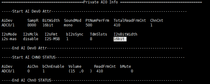
Fig 3-1
-
Debug info analysis
Record the current AI usage status and device/channel attributes, and can dynamically obtain information, which is convenient for debugging and testing.
-
Parameter
Table 3‑1
Parameter Description AI Device Attr AiDev AI device name SamR Sample Rate:8000, 16000, 32000, 48000 BitWidth Bit Width:16bit SoundMod Sond mode:
mono
stereo
queue: all channels are in one bufferPtNumPerFrm Sampling points per frame TotalReadFrmCnt Count of data read from mhal ChnCnt current device hannels I2sMode I2S Rx working mode(Only valid when the device is I2S Rx)
i2s-mas: I2S master
i2s-sla: I2S slave
tdm-mas: TDM master
tdm-sla: TDM slaveI2sMclk Mclk frequency of I2S Rx(Only valid when the device is I2S Rx)
disable: no Mclk
Other values are the current Mclk frequencyI2sFmt I2S Rx data Format(Only valid when the device is I2S Rx)
I2S-MSB: I2S
LEFT-MSB: I2S align leftbI2sSync Whether I2S RX and TX share clock(Only valid when the device is I2S Rx)
1: 4 wire mode,RX and TX share clock
0: 6 wire mode, RX and TX have independent clocksTdmSlots I2S Rx TDM slot number(Only valid when the device is I2S Rx and in TDM mode) I2sBitWidth I2S RX Bit Width(Only valid when the device is I2S Rx and the chip supports TDM mode) Table 3‑2
Parameter Description AI Chn Status AiDev AI device name AiChn AI channel number bChnEnable Whether the AI channel is enabled
1: Enable
0: DisableVolume AI channel gain setting(front gain, rear gain), only Amic/Line has two levels of gain, corresponding to analog gain and digital gain; Dmic only has digital gain, I2S Rx does not support gain. ReadFrmCnt Frames acquired by AI channel bMute Whether the AI channel uses the mute function
3.1.1. echo
Table 3-3
| Function | Dynamically enable/disable AI device to dump pcm data |
|---|---|
| Command | echo dump [Path] [ON/on/1, OFF/off/0] > proc/mi_modules/mi_ao/mi_ao[ID] |
| Parameter description | [Path] Path to save dumped file [ON/on/1, OFF/off/0] Enable or not [ID] AI device ID |
| Example | echo dump /tmp 1 > proc/mi_modules/mi_ao/mi_ai0 |
Table 3-4
| Function | Dynamically enable/disable AI device to dump pcm data (dump all channels in DMA) |
|---|---|
| Command | echo dump_mhal_chn [Path] [ON/on/1, OFF/off/0] > proc/mi_modules/mi_ao/mi_ao[ID] |
| Parameter description | [Path] Path to save dumped file [ON/on/1, OFF/off/0] Enable or not [ID] AI device ID |
| Example | echo dump_mhal_chn /tmp 1 > proc/mi_modules/mi_ao/mi_ai0 |
Table 3-5
| Function | Dynamically set the gain of AI channel |
|---|---|
| Command | echo set_ai_volume [ChnID] [Front Gain] [Rear Gain] > proc/mi_modules/mi_ao/mi_ao[ID] |
| Parameter description | [ChnID] AI channel number [Front Gain] Front gain [Rear Gain] Rear gain, fill in 0 for device without rear gain |
| Example | echo set_ai_volume 0 15 0 > proc/mi_modules/mi_ao/mi_ai0 |
4. AO
4.1. cat
-
Debug info
# cat proc/mi_modules/mi_ao/mi_ao0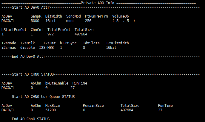
Fig 4-1
-
Debug info analysis
Record the current AO usage status and device/channel attributes, and can dynamically obtain information, which is convenient for debugging and testing.
-
Parameter
Table 4‑1
Parameter Description AO Device Attr AoDev AO device name SamR Sample Rate:8000, 11025, 16000, 22050, 24000, 32000, 44100, 48000 BitWidth Bit Width:16bit SondMod Sond mode:
mono
stereoPtNumPerFrm Sampling points per frame VolumeDb AO device gain (left channel, right channel) bStartPcmOut Whether to broadcast ChnCnt AO device channel number TotalFrmCnt Frames sent by APP to AO device TotalSize Data sent by APP to AO device I2sMode I2S Tx working mode(Only valid when the device is I2S Tx)
i2s-mas: I2S master
i2s-sla: I2S slave
tdm-mas: TDM master
tdm-sla: TDM slaveI2sMclk Mclk frequency of I2S Tx(Only valid when the device is I2S Tx)
disable: no Mclk
Other values are the current Mclk frequencyI2sFmt I2S Tx data Format(Only valid when the device is I2S Tx)
I2S-MSB: I2S
LEFT-MSB: I2S align leftbI2sSync Whether I2S RX and TX share clock(Only valid when the device is I2S Tx)
1: 4 wire mode, RX and TX share clock
0: 6 wire mode, RX and TX have independent clocksTdmSlots I2S Tx TDM slot number(Only valid when the device is I2S Tx and in TDM mode) I2sBitWidth I2S TX Bit Width(Only valid when the device is I2S Tx and the chip supports TDM mode) Table 4-2
Parameter Description AO Chn Status AoDev AO device name AoChn AO channel number bMuteEnable Whether mute is enabled on the AO channel
1: Enable
0: DisableRunTime Enable time of AO channel (unit: s) Table 4-3
Parameter Description AO Chn Usr Queue Status AoDev AO device name AoChn AO channel number MaxSize AO channel queue size (unit: byte) RemainSize The current data in the AO channel Queue (unit: byte) TotalSize Data sent by APP to AO channel (unit: byte) RunTime AO channel queue created time (unit: s)
4.2. echo
Table 4‑4
| Function | Dynamically enable/disable the AO device mute mode |
|---|---|
| Command | echo set_ao_mute [ON/on/1, OFF/off/0] > proc/mi_modules/mi_ao/mi_ao[ID] |
| Parameter description | [ON/on/1, OFF/off/0] enable/disable mute mode [ID] device number |
| Example | echo set_ao_mute 1 > proc/mi_modules/mi_ao/mi_ao[ID] |
Table 4-5
| Function | Dynamically modify the AO channel volume |
|---|---|
| Command | echo set_ao_volume [ChnID] [-60 ~ 30dB] > proc/mi_modules/mi_ao/mi_ao[ID] |
| Parameter description | [ChnID] AO device physical channel number [-60 ~ 30dB] AO device physical channel volume |
| Example | echo set_ao_volume 0 0 > proc/mi_modules/mi_ao/mi_ao0 |
Table 4-6
| Function | Dynamically modify the AO channel recovery data volume |
|---|---|
| Command | echo set_ao_src_volume [ChnID] [-60 ~ 30dB] > proc/mi_modules/mi_ao/mi_ao[ID] |
| Parameter description | [ChnID] AO device physical channel number [-60 ~ 30dB] AO device physical channel recovery data volume |
| Example | echo set_ao_src_volume 0 0 > proc/mi_modules/mi_ao/mi_ao0 |
Table 4-7
| Function | Dynamically enable/disable the dump data function of AO device |
|---|---|
| Command | echo dump [Path] [ON/on/1, OFF/off/0] > proc/mi_modules/mi_ao/mi_ao[ID] |
| Parameter description | [Path] Path to save dump data [ON/on/1, OFF/off/0] enable/disable the dump data function |
| Example | echo dump /tmp 1 > proc/mi_modules/mi_ao/mi_ao0 |
5. VIF 2.0
5.1. cat
-
Debug info
#cat /proc/mi_modules/mi_vif/mi_vif0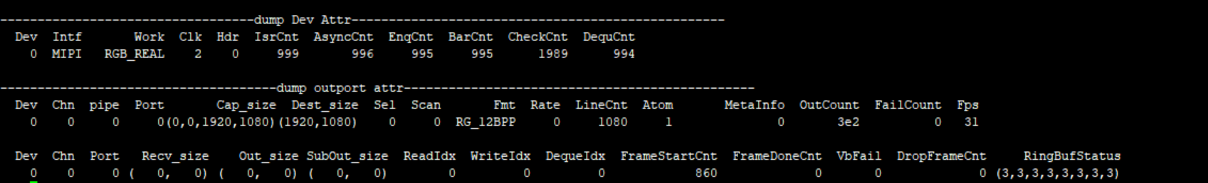
Fig 5-1
-
Debug info analysis
Record the current VIF usage status and device/output attributes, and can dynamically obtain information, which is convenient for debugging and testing.
-
Parameter
Table 5‑1
Parameter Description Dev Attr u32VifDevIdx Dev ID Intf Protocol for inputting data Work Runmode Clk Clock edge trigger mode, related to Intf Hdr Hdr type IsrCnt Frame start callback count AsyncCnt/EnqCnt/ BarCnt/CheckCnt/ DequCnt Callback execution times Table 5‑2
Parameter Description OutPort Attr Chn Channel id Pipe Pipe id Port Port id Cap_size Input size Dest_size output size Sel Frame selection Scan Scan mode, P or I Fmt Out put pixel format Rate Frame rate type LineCnt Frame mode line count Atom Bottom buffers MetaInfo Frame id Outcount Output frame count Failcount Get outputbuffer failure times Fps Frame per second Recv_size Vif HW received size Out_size Write dma size SubOut_size Write sub dma size ReadIdx/WriteIdx/ DequeIdx Index of read,write,deque FrameStartCnt Frame start count FrameDoneCnt Processed frames count VbFail VbFail count DropFrameCnt Dropped frame count RingBufStatus Ring buf status
5.1.1. echo
Table 5‑3
| Function | Dump frame to the specified path |
|---|---|
| Command | echo dump [chnid portid /path] > /proc/mi_modules/mi_vpe/mi_vpe0 |
| Parameter description | Chnid: channel id Portid: port id Path: Storage path |
| Example | echo dump 0 0 /tmp > /proc/mi_modules/mi_vif/mi_vif0 |
Table 5‑4
| Function | Set vif atom number |
|---|---|
| Command | echo initatom [chnid InitAtom] > /proc/mi_modules/mi_vpe/mi_vpe0 |
| Parameter description | Chnid: channel id InitAtom: Driver's buffer max value |
| Example | echo initatom 0 2 > /proc/mi_modules/mi_vif/mi_vif0 |
Table 5‑5
| Function | Set timer |
|---|---|
| Command | echo usetimer [devid bUseTimer] > /proc/mi_modules/mi_vpe/mi_vpe0 |
| Parameter description | devid: device id bUseTimer: Enable timer |
| Example | echo usetimer 0 1 > /proc/mi_modules/mi_vif/mi_vif0 |
6. VIF 3.0
6.1. cat
-
Debug info
#cat /proc/mi_modules/mi_vif/mi_vif0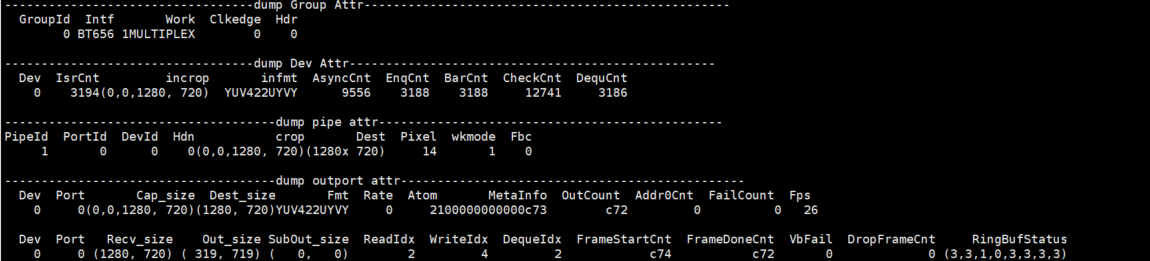
Fig 6-1
-
Debug info analysis
Record the current VIF usage status and Group/Dev/pipe/outport attributes, and can dynamically obtain information, which is convenient for debugging and testing.
-
Parameter
Table 6-1
Parameter Description Group Attr GroupId Device number Intf Protocol for inputting data Work working mode Clkedge Clock edge trigger mode, related to Intf Hdr Hdr type Table 6-2
Parameter Description Dev Attr Dev Dev number IsrCnt Interrupt times that received incrop Input Corp Size infmt Input data format AsyncCnt/EnqCnt/ BarCnt/CheckCnt/ DequCnt Callback execution times Table 6-3
Parameter Description Pipe Attr PipeId Pipe number PortId Port number DevId Dev number Hdn Enable Hdn crop Input Corp Size Dest Output Size Pixel Output Pixel wkmode Pipe working mode Fbc Enabling Fbc Table 6-4
Parameter Description OutPort Attr Dev Channel id Port Pipe id Cap_size Input size Dest_size Output size Fmt Out put pixel format Rate Frame rate type Atom Bottom buffers MetaInfo Frame id OutCount Output frame count Addr0Cnt Frame address 0 count FailCount Get outputbuffer failure times Fps Frame per second Recv_size Vif HW received size Out_size Write dma size SubOut_size Write sub dma size ReadIdx/WriteIdx/ DequeIdx Index of read,write,deque FrameStartCnt Frame start count FrameDoneCnt Processed frames count VbFail VbFail count DropFrameCnt Dropped frame count RingBufStatus Ring buf status
6.2. echo
# echo help >/proc/mi_modules/mi_vif/mi_vif0
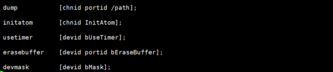
Fig 6-2 Commands
Table 6-5
| Function | Dump frame to the specified path |
|---|---|
| Command | echo dump [chnid portid /path] > /proc/mi_modules/mi_vpe/mi_vpe0 |
| Parameter description | Chnid: channel id Portid: port id Path: storage path |
| Example | echo dump 0 0 /tmp > /proc/mi_modules/mi_vif/mi_vif0 |
Table 6-6
| Function | Set vif atom number |
|---|---|
| Command | echo initatom [chnid InitAtom] > /proc/mi_modules/mi_vpe/mi_vpe0 |
| Parameter description | Chnid: channel id InitAtom: Driver's buffer max value |
| Example | echo initatom 0 2 > /proc/mi_modules/mi_vif/mi_vif0 |
Table 6-7
| Function | Set timer |
|---|---|
| Command | echo usetimer [devid bUseTimer] > /proc/mi_modules/mi_vpe/mi_vpe0 |
| Parameter description | devid: device id bUseTimer: Enable timer |
| Example | echo usetimer 0 1 > /proc/mi_modules/mi_vif/mi_vif0 |
Table 6-8
| Function | Erase vif buffer |
|---|---|
| Command | echo erasebuffer [devid portid bEraseBuffer] > /proc/mi_modules/mi_vpe/mi_vpe0 |
| Parameter description | devid: device id portid: port id EraseBuffer: Erase buffer |
| Example | echo erasebuffer 0 0 1 > /proc/mi_modules/mi_vif/mi_vif0 |
Table 6-9
| Function | Set Dev Mask |
|---|---|
| Command | echo devmask [devid bMask] > /proc/mi_modules/mi_vpe/mi_vpe0 |
| Parameter description | devid: device id bmask: Enable mask |
| Example | echo devmask 0 1 > /proc/mi_modules/mi_vif/mi_vif0 |
7. VPE
7.1. cat
-
Debug info
# cat /proc/mi_modules/mi_vpe/mi_vpe0
Fig 7‑1
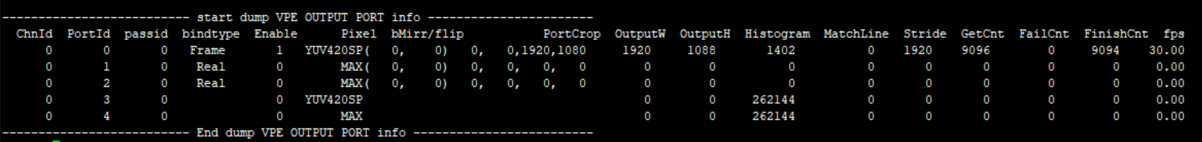
Fig 7‑2
-
Debug info analysis
Record the current VPE usage status and device/output attributes, and can dynamically obtain information, which is convenient for debugging and testing.
-
Parameter
Table 7‑1
Parameter Description Device Info DevID 0, only have one device, the ID is 0 InitCnt connected module times CreChnNum Create Channels Point The running node stops point scllevel Scl½ level chip Chip number cmdq(0,1,2) Cmdq pointer, confirm whether it is shared with other pass IrqName IRQ name En Enable IRQ Mode IRQ mode num IRQ ID VsyncCnt ISR vsync Cnt FrameDoneCnt ISR Frame Done Cnt DropCnt IRQ Frame Drop or Double Vsync LowLatencyIsrCnt Low Lantency Mode Match Line IRQ Cnt Table 7‑2
Parameter Description Channel Info ChnId Channel ID status E_MI_VPE_CHANNEL_STATUS_INITED = 0, E_MI_VPE_CHANNEL_STATUS_START, E_MI_VPE_CHANNEL_STATUS_STOP, E_MI_VPE_CHANNEL_STATUS_DESTROYED, E_MI_VPE_CHANNEL_STATUS_NUM, MaxWH Max width/height bEnLdc Enable Ldc ChnPortMode Port mode, used to choose SCL source, ISP Realtime or RDMA SensorId Bind sensorId RunMode VPE Running mode : VIF-VPE Crop Channel Crop position Rot Rotation angle Mirror/Flip Chn mirror/flip Gardient Isp Gardient ActEn Enable ISP->SCL connection, when the value is 0 means there is a realtime connection 3DNRLevel 3dnr level HdrMode Hdr mode passid passid bUsed Use Pass or not InSize input width/height Inpixel Input Pixel format InStride Input buffer stride SclOutMode Set Scl output mode SclInSize Scl input size Atom Bottom buffers Atom0Cnt There is no buffer at the bottom after released PreCnt/EnqCnt/BarCnt/checkin/ checkout/DeqCnt/DropCnt Callback execution times EnqOTNull When Enq, OutBuffer is statistics of Null Table 7‑3
Parameter Description Outputport Info ChnId Channel ID PortId Port ID passid Pass ID bindtype 0: Real Time mode
1: Ring mode
2: frame modeEnable Enable status Pixel Output pixel format bMirr/flip Port mirror/flip PortCrop Port crop range OutputW /OutputH Output width/height Histogram Scl Histogram MatchLine Low Lantency Mode Match Line Cnt Stride Output buffer stride, a row of pixel bytes GetCnt Get outputbuffers FailCnt Get the times of outputbuffer faliure FinishCnt Processed output buffers fps Output port frame rate
7.2. echo
# echo help > /proc/mi_modules/mi_vpe/mi_vpe0
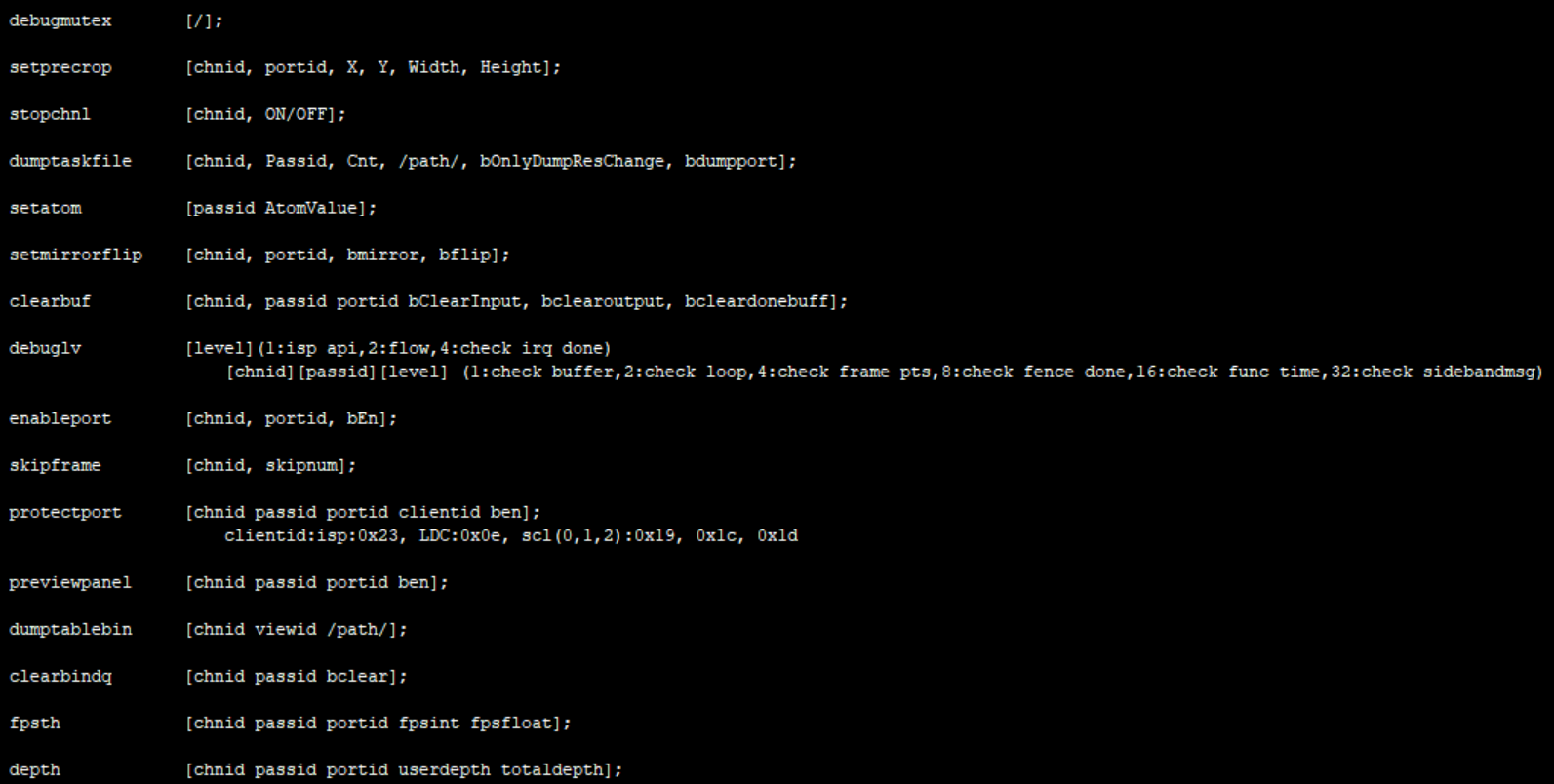
Fig 7‑3 Commands
Table 7‑4
| Function | Print all functions/line/time used by the channel locks |
|---|---|
| Command | echo debugmutex > /proc/mi_modules/mi_vpe/mi_vpe0 |
| Parameter description | None |
| Example | None |
Table 7‑5
| Function | Set the crop parameter for each scl port, which is directly set to the driver, without passing through the MI process |
|---|---|
| Command | echo setprecrop [chnid portid X Y Width Height] > /proc/mi_modules/mi_vpe/mi_vpe0 |
| Parameter description | Chnid: channel id Portid: port id X,Y,width,height: crop range |
| Example | echo setprecrop 0 0 0 0 800 200 > /proc/mi_modules/mi_vpe/mi_vpe0 |
Table 7‑6
| Function | Disable the channel after the bottom buffer is processed, and no longer trig the bottom. |
|---|---|
| Command | echo stopchnl [chnid, ON/OFF] > /proc/mi_modules/mi_vpe/mi_vpe0 |
| Parameter description | Chnid: channel id ON/OFF: Enable/disable stopchannel |
| Example | echo stopchnl 0 ON > /proc/mi_modules/mi_vpe/mi_vpe0 echo stopchnl 0 OFF > /proc/mi_modules/mi_vpe/mi_vpe0 |
Table 7‑7
| Function | Dump specified channel and pass the output data, save it in /path |
|---|---|
| Command | echo dumptaskfile [chnid, Passid, Cnt, /path/, bOnlyDumpResChange, bdumpport] > /proc/mi_modules/mi_vpe/mi_vpe0 |
| Parameter description | Chnid: channel id Passid: pass id Cnt: dump number Path: Store dump files bOnlyDumpResChange: Blurred images may be generated when switching resolutions. The dump command and switching resolution operations are not easy to perform together. You can set this parameter first, and then switch the resolution. After the program recognizes it, the buffer after the resolution change will be dumped. (Optional)) Bdumpport: Only dump a certain portid, the default is to dump all the ports in the output. (Optional) |
| Example | echo dumptaskfile 0 0 2 /tmp > /proc/mi_modules/mi_vpe/mi_vpe0 |
Table 7‑8
| Function | Set the passed atomvalue |
|---|---|
| Command | echo setatom [passid AtomValue] > /proc/mi_modules/mi_vpe/mi_vpe0 |
| Parameter description | Passid: pass id AtomValue: Driver's buffer max value in input realtime mode |
| Example | echo setatom 0 3 > /proc/mi_modules/mi_vpe/mi_vpe0 Note: Increase the atom when the bottom layer is stuck, add a buffer to the driver, and re-trig to see if it recovers, or increase it when the frame is dropped to see if the frame can be full. |
Table 7‑9
| Function | Set the output screen of the channel and port to see if it can be flipped |
|---|---|
| Command | echo setmirrorflip [chnid, portid, bmirror, bflip] > /proc/mi_modules/mi_vpe/mi_vpe0 |
| Parameter description | Chnid: channel id Portid: port id bmirror: Mirror flip bflip: Flip up and down |
| Example | echo setmirrorflip 0 0 1 0 > /proc/mi_modules/mi_vpe/mi_vpe0 Mirror flip |
Table 7‑10
| Function | Clear the input/output/done buffer of the specified channel pass port |
|---|---|
| Command | echo clearbuf [chnid, passid portid bClearInput, bclearoutput, bcleardonebuff] > /proc/mi_modules/mi_vpe/mi_vpe0 |
| Parameter description | Chnid: channel id Passid: pass id Portid: port id bClearInput: Clear the input buffer bclearoutput: Clear the output buffer bcleardonebuff: Clear the completed buffer |
| Example | echo clearbuf 0 0 0 1 0 0 > /proc/mi_modules/mi_vpe/mi_vpe0 |
Table 7‑11
| Function | Set debug level |
|---|---|
| Command | echo debuglv [level] >/proc/mi_modules/mi_vpe/mi_vpe0 echo debuglv [chnid][passid][level] >/proc/mi_modules/mi_vpe/mi_vpe0 |
| Parameter description | Chnid: channel id passid: pass id Level: Single level parameter: 1:isp api,2:flow,4:check irq done Three parameters: 1:check buffer,2:check loop,4:check frame pts,8:check fence done,16:check func time,32:check sidebandmsg,64:check zoominfo |
| Example | echo debuglv 4 > /proc/mi_modules/mi_vpe/mi_vpe0 //Open check irq done related MI print echo debuglv 0 0 3 > /proc/mi_modules/mi_vpe/mi_vpe0 //Open channel0 pass0 level3 printing to print buffer info and loop info |
Table 7‑12
| Function | Enabling port or not |
|---|---|
| Command | echo enableport [chnid, portid, bEn] > /proc/mi_modules/mi_vpe/mi_vpe0 |
| Parameter description | Chnid: channel id Portid: port id bEn: 1/0 |
| Example | echo enableport 0 0 1 > /proc/mi_modules/mi_vpe/mi_vpe0 |
Table 7‑13
| Function | Drop frame count |
|---|---|
| Command | echo skipframe [chnid, skipnum] > /proc/mi_modules/mi_vpe/mi_vpe0 |
| Parameter description | Chnid: channel id skipnum: drop frame count |
| Example | echo skipframe 0 60 > /proc/mi_modules/mi_vpe/mi_vpe0 |
Table 7‑14
| Function | Protect outputport buffer |
|---|---|
| Command | echo protectport [chnid passid portid clientid ben] > /proc/mi_modules/mi_vpe/mi_vpe0 |
| Parameter description | Chnid: channel id Passid: pass id Portid: port id Clientid: isp:0x23, LDC:0x0e, scl(0,1,2):0x19, 0x1c, 0x1d ben: Enable |
| Example | echo protectport 0 0 0 0x23 1 > /proc/mi_modules/mi_vpe/mi_vpe0 // Protect isp in channel0 pass0 port0 |
Table 7‑15
| Function | Dump LDC view table |
|---|---|
| Command | echo dumptablebin [chnid viewid /path/] > /proc/mi_modules/mi_vpe/mi_vpe0 |
| Parameter description | Chnid: channel id viewid path |
| Example | echo dumptablebin 0 1 /mnt > /proc/mi_modules/mi_vpe/mi_vpe0 |
Table 7‑16
| Function | Consume the buffer cached in Bind Q |
|---|---|
| Command | echo clearbindq [chnid passid bclear] > /proc/mi_modules/mi_vpe/mi_vpe0 |
| Parameter description | Chnid: channel id Passed: pass id bclear: clear or not |
| Example | echo clearbindq 0 0 1 > /proc/mi_modules/mi_vpe/mi_vpe0 //clear channel0 pass0 bindQ Consume the buffer cached in Bind Q. The VPE BindQ is full and the front-end cannot get the buffer, and judge whether the VPE is too slow. Clear bindQ and observe whether it will accumulate. If it is, the VPE is too slow, if not, the previous exception is not consumed. |
Table 7‑17
| Function | Set the print frame rate, print if it is lower than this value |
|---|---|
| Command | echo fpsth [chnid passid portid fpsint fpsfloat] > /proc/mi_modules/mi_vpe/mi_vpe0 |
| Parameter description | Chnid: channel id passid: pass id Portid: port id fpsint: Frame rate integer bits fpsfloat: Frame rate decimal bits |
| Example | echo fpsth 0 0 0 30 30 > /proc/mi_modules/mi_vpe/mi_vpe0 // Print the fps which is less than 30.30 in channel0 pass0 port0 |
Table 7‑18
| Function | Set vpe outport depth |
|---|---|
| Command | echo depth [chnid passid portid userdepth totaldepth] > /proc/mi_modules/mi_vpe/mi_vpe0 |
| Parameter description | Chnid: channel id Passid: pass id Portid: port id Userdepth: User output buffer Totaldepth: Tatal output buffers |
| Example | echo depth 0 0 0 2 4 > /proc/mi_modules/mi_vpe/mi_vpe0 |
8. VENC
8.1. cat
-
Debug info
#cat /proc/mi_modules/mi_venc/mi_vencN //Before Venc 3.0, N is 0/1, 0 is device0 that encodes h264 and h265, and 1 is device1 that encodes jpeg; Venc 3.0, N is 0/8, 0is device0 that encodes h264 and h265, 8 is device8 that encodes jpeg.
Fig 8-1
-
Debug info analysis
Record the current VENC device usage status and device/layer/inputport attributes, and can dynamically obtain information, which is convenient for debugging and testing.
-
Parameter
Table 8-1
Parameter Description Dev info DevId Device number, used as Dev ID (Mapping the kernel MI_VENC_Dev_e) IrqNum Interrupt number IsrTotalCnt Various types of irqs IsrFrmDoneCnt frame done irq IsrBufFullCnt irq count for buffer full type IsrSliceDoneCnt isr count for slice done IsrRingFullCnt irq count for ring buffer full type IsrTimeoutCnt Count for timeout isr IsrOtherCnt irq count for other type MaxTaskCnt Max task supported for processing at the same time WorkingTaskCnt The number of working task SupportRing Support HW RING or not SupportImi Support HW REALTIME or not NeedPadding Need MI SYS clear padding or not CmdqHandle cmdq handle value CmdqBufSize CmdqBufSize ResetTime Device reset time MaxW The width of the max resolution used by device MaxH The height of the max resolution used by device AlignMaxw The aligned max width AlignMaxH The aligned max height Table 8-2
Parameter Description CHN info ChnId Channel ID bStart Started receiving data or not RefMemPA The HW physical address required by bottom driver RefMemSize The HW memory size required by bottom driver AlMemPA The CPU physical address required by bottom driver AlMemVA The CPU virtual address required by bottom driver AlMemSize The CPU memory size required by bottom driver State Bottom processing status:
typedef enum
{
E_MI_VENC_BUFSTATE_IDLE = 0,
E_MI_VENC_BUFSTATE_ENCODE,
E_MI_VENC_BUFSTATE_WAIT_CMDQ,
E_MI_VENC_BUFSTATE_CHECK,
E_MI_VENC_BUFSTATE_DROP,
E_MI_VENC_BUFSTATE_DROP_FORCE,
E_MI_VENC_BUFSTATE_RECOVER,
E_MI_VENC_BUFSTATE_BUF_FULL,
E_MI_VENC_BUFSTATE_MAX
} MI_VENC_BufferState_e;EnPred Whether the base-level frame is used as a reference by other frames in this level base Period of base-level, value range: (0, +∞) enhance Period of enhance-level, value range: [0, 255] MaxStreamCnt The max outputed buffers FrameIdx Cuurent frame ID:
before venc3.0, the value is 1, 2, 3 or 4;
after venc3.0, the value is 1, 2 or 4Gardient The gradient value passed by the front-end isp Fps_1s Count the output frame rate within 1s kbps Count the output bit rate within 1s Fps10s Count the output frame rate within 10s kbps Count the output code rate within 10s RingBufStartLine ring start line in ring mode RingBufHeight ring buffer height in ring mode QueryCnt The times for APP calling MI_VENC_Query GetStreamCnt The times for APP calling MI_VENC_GetStream RlsStreamCnt The times for APP calling MI_VENC_ReleaseStream PollReadyCnt The successful times for APP calling select/poll PollFailCnt The failed times for APP calling select/poll Table 8-3
Parameter Description Inputport info ChnId Channel ID Width Pixel width Height Pixel height SrcFrmRate Source frames per second, usually used as a parameter of rate control MaxW Max pixel width MaxH Max pixel height FrameCnt Processed frames DropFrameCnt Dropped frame count BlockCnt The input pictures have been received, but the previous input picture is still being processed and needs to be rewinded Table 8-4
Parameter Description Outputport info ChnId Channel ID CODEC CODEC: H264,H265,MJPG Profile BufSize Max buffer per frame set by user (bytes) MinAllocSize Min allocte size RefNum Max reference frames bByFrame Whether the rear level takes one frame at a time
0: N, get data by package
1: YFrameCnt Processed frames DropCnt Frames that have been encoded but dropped ReEncCnt Recoded frames RingUnreadCnt Frames in the output pool that have not yet been taken RingTotalCnt Frames in the output pool UsrLockedCnt Frames locked by user RateCtl Rate Control algorithm: CBR, VBR, FixQp, etc. GOP Group of Picture MaxBitrate When it is CBR or VBR, the maximum target bit rate. (bits per second) IPQPDelta The difference between the average QP value and the QP of the current I frame MaxQp When it is VBR, the max allowed QP MinQp When it is VBR, the min allowed QP MaxIQP When it is VBR, the max allowed I frame QP MinIQP When it is VBR, the min allowed I frame QP QpMap Allow users to decide rate control in QPMAP mode AbsQp Use absolute Qp ModeMap 0 decided byhw;1 force skip;2 force intra
8.2. echo
Table 8-5
| Function | dump input buffer |
|---|---|
| Command | echo dump_in [ChnId] [num] > /proc/mi_modules/mi_venc/mi_venc[DevID] |
| Parameter description | [ChnId] : Channel number [num] : The total for dump_in [DevID] : Device number [0~1] 0: device0 that encodes h264 and h265 1: device1 that encodes jpeg |
| Example | echo dump_in 0 10 /mnt > /proc/mi_modules/mi_venc/mi_venc0 |
Table 8‑6
| Function | dump output stream |
|---|---|
| Command | echo dump_out [ChnId] [num] > /proc/mi_modules/mi_venc/mi_venc[DevID] |
| Parameter description | [ChnId] : Channel number [num]: The total for dump_out [DevID] : Device number [0~1] 0: device0 that encodes h264 and h265 1: device1 that encodes jpeg |
| Example | echo dump_out 0 100 /mnt > /proc/mi_modules/mi_venc/mi_venc1 |
Table 8‑7
| Function | Show all used device info |
|---|---|
| Command | echo show all [Status] > /proc/mi_modules/mi_venc/mi_venc[DevID] |
| Parameter description | [Status] :0-1 0:Show only requested device info 1:Show all used device info. with created channels [DevID] : Device number [0~1] 0: device0 that encodes h264 and h265 1: device1 that encodes jpeg |
| Example | echo show_all 1 > /proc/mi_modules/mi_venc/mi_venc0 |
Table 8-8
| Function | show output frame countparam |
|---|---|
| Command | echo frame_cnt [ChnId] > /proc/mi_modules/mi_venc/mi_venc[DevID] |
| Parameter description | [ChnId] : Channel number [DevID] : Device number [0~1] 0: device0 that encodes h264 and h265 1: device1 that encodes jpeg |
| Example | echo frame_cnt 0 > /proc/mi_modules/mi_venc/mi_venc0 |
Table 8-9
| Function | Drop/Release the corresponding channel output task |
|---|---|
| Command | echo drop_out [ChnId] [Status]> /proc/mi_modules/mi_venc/mi_venc[DevID] |
| Parameter description | [ChnId] : Channel number, when it is a, it represents all channels [Status] : r : release the corresponding channel output task d : drop the corresponding channel output task [DevID] : Device number [0~1] 0: device0 that encodes h264 and h265 1: device1 that encodes jpeg |
| Example | echo drop_out 0 d > /proc/mi_modules/mi_venc/mi_venc0 Note: drop channel 0 output task echo drop_out 0 r > /proc/mi_modules/mi_venc/mi_venc0 Note: release channel 0 output task echo drop_out a d > /proc/mi_modules/mi_venc/mi_venc0 Note: drop the whole channel output task echo drop_out a r > /proc/mi_modules/mi_venc/mi_venc0 Note: release the whole channel output task |
Table 8-10
| Function | Drop/Release the corresponding channel input task |
|---|---|
| Command | echo drop_in [ChnId] [Status]> /proc/mi_modules/mi_venc/mi_venc[DevID] |
| Parameter description | [ChnId] : Channel number, when it is a, it represents all channels [Status] : r : release the corresponding channel input task d : drop the corresponding channel input task [DevID] : Device number [0~1] 0: device0 that encodes h264 and h265 1: device1 that encodes jpeg |
| Example | echo drop_in 0 d > /proc/mi_modules/mi_venc/mi_venc0 Note: drop channel 0 input task echo drop_in 0 r > /proc/mi_modules/mi_venc/mi_venc0 Note: release channel 0 input task echo drop_in a d > /proc/mi_modules/mi_venc/mi_venc0 Note: drop the whole channel input task echo drop_in a r > /proc/mi_modules/mi_venc/mi_venc0 Note: release the whole channel input task |
Table 8-11
| Function | Set debug level for super frame flow |
|---|---|
| Command | echo dbg_supfrm [ChnId] [debug_level]> /proc/mi_modules/mi_venc/mi_venc[DevID] |
| Parameter description | [ChnId] : Channel number [debug_level]: 0.none 1.warn 2.info [DevID] : Device number [0~1] 0: device0 that encodes h264 and h265 1: device1 that encodes jpeg |
| Example | echo dbg_supfrm 0 2 > /proc/mi_modules/mi_venc/mi_venc0 |
Table 8-12
| Function | Set debug level for super frame lost flow |
|---|---|
| Command | echo dbg_frmlost [ChnId] [debug_level]> /proc/mi_modules/mi_venc/mi_venc[DevID] |
| Parameter description | [ChnId] : Channel number [debug_level]: 0.none 1.warn 2.info [DevID] : Device number [0~1] 0: device0 that encodes h264 and h265 1: device1 that encodes jpeg |
| Example | echo dbg_frmlost 0 2 > /proc/mi_modules/mi_venc/mi_venc0 |
Table 8-13
| Function | Set debug level for get frame flow |
|---|---|
| Command | echo dbg_getout [ChnId] [debug_level]> /proc/mi_modules/mi_venc/mi_venc[DevID] |
| Parameter description | [ChnId] : Channel number [debug_level]: 0.none 1.warn 2.info [DevID] : Device number [0~1] 0: device0 that encodes h264 and h265 1: device1 that encodes jpeg |
| Example | echo dbg_getout 0 2 > /proc/mi_modules/mi_venc/mi_venc0 |
Table 8-14
| Function | dump dump customer qp map |
|---|---|
| Command | echo dump_map $channel_num $dump_times $dump_path > /proc/mi_modules/mi_venc/mi_venc0 |
| Parameter description | [ChnId] : Channel number $channel_num : channel_num $dump_times : dump times $dump_path : dump path [DevID] : Device number [0~1] 0: device0 that encodes h264 and h265 |
| Example | echo dump_map 0 1 /mnt > /proc/mi_modules/mi_venc/mi_venc0 |
Table 8-15
| Function | Dump the corresponding phyAddr |
|---|---|
| Command | echo dump_dram [ChnId]> /proc/mi_modules/mi_venc/mi_venc[DevID] |
| Parameter description | [ChnId] : Channel number [DevID] : Device number [0~1] 0: device0 that encodes h264 and h265 1: device1 that encodes jpeg |
| Example | echo dump_dram 0 /mnt > /proc/mi_modules/mi_venc/mi_venc0 |
Table 8-16
| Function | Enable to run shell scripts when hang |
|---|---|
| Command | echo run_sh [Status] [path]> /proc/mi_modules/mi_venc/mi_venc[DevID] |
| Parameter description | [Status]: 1:enable 0:disable [path]: file path [DevID] : Device number [0~1] 0: device0 that encodes h264 and h265 1: device1 that encodes jpeg |
| Example | echo run_sh 1 /mnt/dump_mhal_venc_status_hook.sh > /proc/mi_modules/mi_venc/mi_venc0 |
Table 8-17
| Function | Enable to recover when hang |
|---|---|
| Command | echo en_recover [Status] > /proc/mi_modules/mi_venc/mi_venc[DevID] |
| Parameter description | [Status]: 1:enable 0:disable; 2:show [DevID] : Device number [0~1] 0: device0 that encodes h264 and h265 1: device1 that encodes jpeg |
| Example | echo en_recover 0 > /proc/mi_modules/mi_venc/mi_venc0 |
Table 8-18
| Function | show output stream info |
|---|---|
| Command | echo show_out [ChnId] > /proc/mi_modules/mi_venc/mi_venc[DevID] |
| Parameter description | [ChnId] : Channel number [DevID] : Device number [0~1] 0: device0 that encodes h264 and h265 1: device1 that encodes jpeg |
| Example | echo show_out 0 > /proc/mi_modules/mi_venc/mi_venc0 |
Table 8-19
| Function | dynamic debug sed roi info or sad info |
|---|---|
| Command | echo debug_sed [ChnId] [SedType] [Status] > /proc/mi_modules/mi_venc/mi_venc[DevID] |
| Parameter description | [ChnId] : Channel number [SedType]: 0: show/disable ive detector algorithm roi info 1: show/disable cnn detector algorithm roi info 2: show/disable motion detector algorithm roi info [Status] : ture:enable false:disable [DevID] : Device number [0~1] 0: device0 that encodes h264 and h265 1: device1 that encodes jpeg |
| Example | echo debug_sed 0 0 true > /proc/mi_modules/mi_venc/mi_venc0 Note: show ive detector algorithm roi info echo debug_sed 0 1 true > /proc/mi_modules/mi_venc/mi_venc0 Note: show cnn detector algorithm roi info echo debug_sed 0 2 true > /proc/mi_modules/mi_venc/mi_venc0 Note: show motion detector algorithm roi info |
Table 8-20
| Function | enable show sram info (m6 platform) |
|---|---|
| Command | echo debug_sram [ChnId] [Status] > /proc/mi_modules/mi_venc/mi_venc[DevID] |
| Parameter description | [ChnId] : Channel number [Status] : ture:enable false:disable [DevID] : Device number [0~1] 0: device0 that encodes h264 and h265 1: device1 that encodes jpeg |
| Example | echo debug_sram 0 true > /proc/mi_modules/mi_venc/mi_venc0 |
9. DIVP
9.1. cat
-
Debug info
# cat /proc/mi_modules/mi_divp/mi_divp0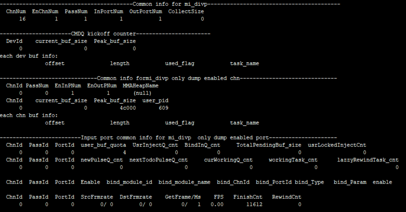
Fig 9‑1
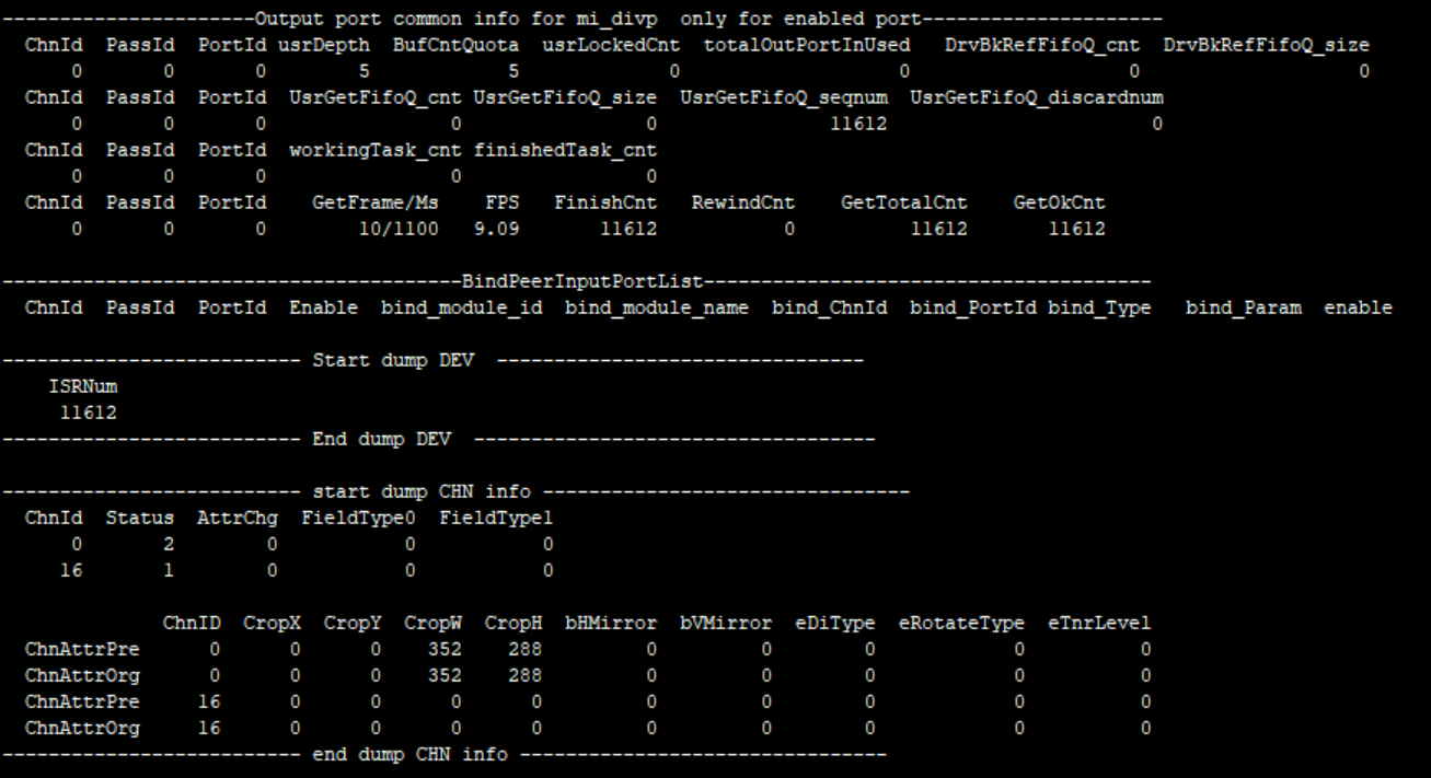
Fig 9‑2
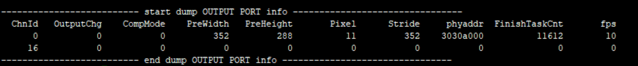
Fig 9‑3
-
Debug info analysis
Record the current DIVP device usage status and device/layer/inputport attributes, and can dynamically obtain information, which is convenient for debugging and testing.
-
Parameter
Table 9‑1
Parameter Description channelinfo ChnId 0~16; 16 Capture Channel is not open to the upper layer Status 0 INITED 1 CREATED 2 STARTED 3 STOPED 4 DISTROYED AttrChg 0: not change 1: changed FieldType0, FieldType1 (last two fields's type) 0 NONE, //\< no field. 1 TOP, //\< Top field only. 2 BOTTOM, //\< Bottom field only. 3 BOTH, //\< Both fields. 4 NUM ChnAttrPre Previous setting attribute of the channel ChnAttrOrg Original setting attributes of the channel CropX, CropY, CropW, CropH The crop position set in the upper layer bHMirror, bVMirror Horizontal flip enable; Vertical flip enable
0:disable ; 1:enableeDiType 0 OFF,//off 1 2D,///2.5D DI 2 3D,///3D DI 3 NUM, eRotateType 0 NONE, //Rotate 0 degrees 1 90, //Rotate 90 degrees 2 180, //Rotate 180 degrees 3 270, //Rotate 270 degrees 4 NUM, eTnrLevel 0 OFF, 1 LOW, 2 MIDDLE, 3 HIGH, 4 NUM, Table 9-2
Parameter Description inputport info ChnId Channel ID 0~16 InputChg Whether the input port attribute has changed bIPChg 0: No change between interlaced and progressive; 1: Switch between interlaced and progressive. PreWidth input port width PreHeight input port height Pixel E_MI_SYS_PIXEL_FRAME_YUV422_YUYV = 0, E_MI_SYS_PIXEL_FRAME_ARGB8888, E_MI_SYS_PIXEL_FRAME_ABGR8888, E_MI_SYS_PIXEL_FRAME_RGB565, E_MI_SYS_PIXEL_FRAME_ARGB1555, E_MI_SYS_PIXEL_FRAME_I2, E_MI_SYS_PIXEL_FRAME_I4, E_MI_SYS_PIXEL_FRAME_I8, E_MI_SYS_PIXEL_FRAME_YUV_SEMIPLANAR_422, E_MI_SYS_PIXEL_FRAME_YUV_SEMIPLANAR_420, E_MI_SYS_PIXEL_FRAME_YUV_MST_420, //vdec mstar private video format E_MI_SYS_PIXEL_FRAME_YC420_MSTTILE1_H264, E_MI_SYS_PIXEL_FRAME_YC420_MSTTILE2_H265, E_MI_SYS_PIXEL_FRAME_YC420_MSTTILE3_H265, E_MI_SYS_PIXEL_FRAME_FORMAT_MAX Stride Input的stride 2Pmode b2P_Enable value. 1: enable; 0: disable EnqueueTask Enqueue task GetInTaskCnt OnPreProcessInputTask number Table 9-3
Parameter Description Outputport Info ChnId Channel ID 0~16 OutputChg the Output attribute has changed or not; 0: N; 1: Y Pixel The same as input pixel CompMode 0 //no compress 1 //compress unit is 256 bytes as a segment 2 //compress unit is the whole line 3 //compress unit is the whole frame 4 //number PreWidth PreHeight The width and height of the output port previously set Stride Output stride phyaddr Output buffer physical address FinishTaskCnt Finished tasks fps Output port frame rate Table 9-4
Parameter Description Common Info ChnNum Channel number Pixel The same as input pixel PassNum Pass number InPortNum Input ports OutPortNum Output ports CollectSize Attached pstAllocators current_buf_size Current buffer size Peak_buf_size Peak buffer size user_pid User pid user_buf_quota User buffer quota UsrInjectQ_cnt User inject buffers BindInQ_cnt Input port enqueue buffers provided by the front-end TotalPendingBuf_size The buffer size of each task in the current input working queue usrLockedInjectCnt The buf currently owned by the user newPulseQ_cnt Buffers of new_pulse_fifo_inputqueque nextTodoPulseQ_cnt Buffers of next_todo_pulse_inputqueue curWorkingQ_cnt Buffers of cur_working_input_queue workingTask_cnt Tasks of input_working_tasklist lazzyRewindTask_cnt Tasks that need retry bind_module_id Bound module id bind_module_name Bound module name bind_ChnId Binding module channel id bind_PortId Binding module port id bind_Type Binding type: E_MI_SYS_BIND_TYPE_FRAME_BASE = 0x00000001, E_MI_SYS_BIND_TYPE_SW_LOW_LATENCY = 0x00000002, E_MI_SYS_BIND_TYPE_REALTIME = 0x00000004, E_MI_SYS_BIND_TYPE_HW_AUTOSYNC = 0x00000008, E_MI_SYS_BIND_TYPE_HW_RING = 0x00000010 bind_Param Bound parameter SrcFrmrate source frame rate DstFrmrate destination frame rate GetFrame/Ms Frames/time FPS Frame rate RewindCnt Tasks that need retry usrDepth The max output port buffers taken by user BufCntQuota The max buffers applied by output port usrLockedCnt The actual buffers received by user totalOutPortInUsed The actual buffers applied by outport DrvBkRefFifoQ_cnt for special driver which need to refer back pre-processed buffer DrvBkRefFifoQ_size The buffer size taken by stDrvBkRefFifoQueue UsrGetFifoQ_cnt Buffers that duplicate to output port UsrGetFifoQ_size The total of buffer size that duplicate to output port UsrGetFifoQ_seqnum The buffers recived by output port UsrGetFifoQ_discardnum Output port applied for a new buffer and abandoned the original finishedTask_cnt Tasks finished by output port GetTotalCnt Buffers got by output port GetOkCnt Count the frames whose index is E_MI_SYS_FRC_OBTAIN ISRNum Interruptions received
9.2. Echo
Table 9-5
| Function | Print the PTS of each frame received, if the front end is VDEC, print the FrameID sent, and debug the frame dropping problem. Normally, the values of FrameID and PTS are both increasing. |
|---|---|
| Command | echo checkframeid [ChnID] [Status] > /proc/mi_modules/mi_divp/mi_divp0 [ChnID] Channel number [0~32] [Status] ON: start printing; OFF: stop printing |
| Example | echo checkframeid 0 ON/OFF > /proc/mi_modules/mi_divp/mi_divp0 [MI DIVP PROCFS]:ChnID 0, receive buffer ID = 63 , H = 0, L = 196615, PTS = 43956000 [MI DIVP PROCFS]:ChnID 0, receive buffer ID = 64 , H = 0, L = 196616, PTS = 43989000 [MI DIVP PROCFS]:ChnID 0, receive buffer ID = 65 , H = 0, L = 196615, PTS = 44022000 [MI DIVP PROCFS]:ChnID 0, receive buffer ID = 66 , H = 0, L = 196615, PTS = 44055000 [MI DIVP PROCFS]:ChnID 0, receive buffer ID = 67 , H = 0, L = 196615, PTS = 44088000 [MI DIVP PROCFS]:ChnID 0, receive buffer ID = 68 , H = 0, L = 196615, PTS = 44121000 [MI DIVP PROCFS]:ChnID 0, receive buffer ID = 69 , H = 0, L = 196614, PTS = 44154000 [MI DIVP PROCFS]:ChnID 0, receive buffer ID = 70 , H = 0, L = 196615, PTS = 44187000; receive buffer ID: buffer ID received by each channel. H,L: FrameID sent by VDEC, H is high 32 bits, L is low 32 bits, nothing for printing when the front-end is not VDEC. PTS: FrameBuffer's PTS. |
Table 9-6
| Function | Count the GetBuffer within 1 second, the average/max/min value and the debug frame dropping problem of the interval between the two inputbuffers. |
|---|---|
| Command | echo statintervaltime [ChnID] ON/OFF > /proc/mi_modules/mi_divp/mi_divp0 |
| Parameter description | [ChnID] Channel number [0~32] [Status] ON: start statistics and printing; OFF: stop statistics and printing |
| Example | echo statintervaltime 0 ON > /proc/mi_modules/mi_divp/mi_divp0 [MI DIVP PROCFS]: ChnlID 0, 1s FrameCnt:19, Average time: 50393 us, MAX 59601 us, 57652 us,57534 us, MIN 41401 us, 42415 us, 42896 us [MI DIVP PROCFS]: ChnlID 0, 1s FrameCnt:19,Average time: 50247 us,MAX 63004 us,62889 us,62845 us,MIN 36896 us, 37120 us, 37130 us [MI DIVP PROCFS]: ChnlID 0, 1s FrameCnt:18, Average time: 51049 us, MAX 70431 us,59763 us, 59736 us, MIN 38873 us,40109 us,40283 us [MI DIVP PROCFS]: ChnlID 0,1s FrameCnt:20, Average time: 48537 us, MAX 67168 us,67117 us,66953 us, MIN 18513 us,31242 us,32681 us [MI DIVP PROCFS]: ChnlID 0,1s FrameCnt:19, Average time: 49962 us, MAX 61416 us, 61416 us, 61338 us, MIN 38564 us, 38736 us, 38762 us FrameCnt: GetBuffers in 1 second; Average time: average time between the two buffers; MAX: the three values with the longest interval; MIN: the three values with the shortest interval |
Table 9-7
| Function | DIVP no longer processes a certain channel to save bandwidth and verify bandwidth related problems |
|---|---|
| Command | echo stoponechannel [ChnID] [Status] > /proc/mi_modules/mi_divp/mi_divp0 |
| Parameter description | [ChnID] Channel number [0~32] [Status] ON: Stop processing the set channel; OFF: continue processing the set channel |
| Example | echo stoponechannel 0 ON > /proc/mi_modules/mi_divp/mi_divp0 Stop the image of channel 0 |
Table 9-8
| Function | dump a input frame. |
|---|---|
| Command | echo dumpframe [ChnID] [frameStorePath] > /proc/mi_modules/mi_divp/mi_divp0 |
| Parameter description | [ChnID] Channel number [0~16]. [ frameStorePath ] input frame storage path. |
| Example | #echo dumpframe 0 /customer > /proc/mi_modules/mi_divp/mi_divp0 dump a input frame in /customer. Default name of input frame. Such as: dump_divp_chn0_frame_w_352_h_288.yuv |
Table 9-9
| Function | Open the debug info of mi divp. |
|---|---|
| Command | echo debug 0/1 > /proc/mi_modules/mi_divp/mi_divp0 |
| Parameter description | [0/1] 0: disable; 1: enable. |
| Example | #echo debug 1 > /proc/mi_modules/mi_divp/mi_divp0 printk in _MI_SYS_IMPL_Common_WriteProc divp debug:on #echo debug 0 > /proc/mi_modules/mi_divp/mi_divp0 printk in _MI_SYS_IMPL_Common_WriteProc divp debug: off |
10. VDISP
10.1. cat
-
Debug info
# cat proc/mi_modules/mi_vdisp/mi_vdisp0

============================Private Vdisp0 Info ===============================

DevStatus

Start

------------------------------------------------------- Input Port Info
---------------------------------------------

PortID PortStatus ChnX ChnY ChnW ChnH IsFreeRun TryOk RecvOk

0 Enabled 0 0 960 540 1 245356299 313332

1 Enabled 960 0 960 540 1 355670297 313332

2 Enabled 0 540 960 540 1 578760014 313331

3 Enabled 960 540 960 540 1 757579130 313330

------------------------------------------------------ Output Port Info
-------------------------------------------------

Inited FrmInterval BgColor PixelFmt FrmRate Width Height SendOk

1 33333 8388736 0 30 1920 1080 471418
-
Debug info analysis
Record the current VDISP usage status and device/Inputport/Outputport attributes, and can dynamically obtain information, which is convenient for debugging and testing.
-
Parameter
Table 10‑1
Parameter Description device info DevStatus Working status of Vdisp; Uninit/ Init/ Start/ Stop Table 10‑2
Parameter Description layer info PortID Inport ID; value range: [0~16], 16 is the overlay channel (PIP channel). PortStatus Port status; Uninit/ Init/ Enabled/ Disabled ChnX Input the X starting coordinate address of the inport; value range: [0~4094], need to be aligned according to the chip ChnY Input the Y starting coordinate address of the inport; value range: [0~2159] ChnW Input the image width of the inport, which needs to be aligned according to the chip
value range:[0~4096]ChnH Input the image height of the inport; value range:[0~4096] IsFreeRun Frame rate control or not; 0: pts control play; 1: free play TryOk Try to get the times that the front-level bound port RecvOk The times that get data from the front-level bound port successfully Table 10‑3
Parameter Description Output port info Inited Output Port has been initialized or not; 0: Uninit; 1: Init FrmInterval Output frame time interval, unit: US BgColor Background color, printed here is decimal PixelFmt Color space; value range: [0~E_MI_SYS_PIXEL_FRAME_FORMAT_MAX-1] 0-YUYV422, 9-YUVSP420 FrmRate Output frame rate Width Image output width; value range: [0~4096], need to be aligned according to the chip Height Image output height; value range:[0~2160], need to be aligned according to the chip SendOk Frame statistics that successful pushed to the rear-level
11. DISP
11.1. cat
-
Debug info
# cat /proc/mi_modules/mi_disp/mi_disp0

============================== disp dev info ============================
DevStatus         IrqNum         IrqCnt        BgColor
1             31              0         800080
================================ disp layer info ===========================
LayerId          BindedDevID           LayerWidth           LayerHeight
    0                    0                    0                     0
LayerId          LayDispWidth        LayDispHeight         Toleration           rotatemode
    0              1024                  600                 0                 NONE
--------------------------------- disp layer[0] port Info ---------------------------------
PortId    enable    CurStatus     src_w     src_h    crop_x    crop_y    crop_w    crop_h    show_x
0         1          0         1024      600       0         0        1024      600        0
show_y    show_w    show_h
0        1024       600
PortId     RecvBufCnt      RecvBuf_W      RecvBuf_H      Content_W      Content_H  RecvBufStride
0           1661           1024            600           1024            600           1024
PixFmt              syncmode
semiplanar_420           Invalid
PortId     OnScreenTask      FiredTask    LastDropTask    DropTaskCnt    StepTaskCnt   bClearAllTask
0           (null)          c2639db8       (null)              0              0              0
fps
0
-
Debug info analysis
Record the current DISP usage status and device/layer/inputport attributes, and can dynamically obtain information, which is convenient for debugging and testing.
-
Parameter
Table 11‑1
Parameter Description device info DevStatus 0: disable; 1: enable IrqNum Interrupt number IrqCnt Interruption times BgColor Background color(RGB format) Table 11-2
Parameter Description layer info LayerId layer ID ; value range:[0~1] BindedDevID Bound device ID; value range:[0~1] LayerWidth Layer Width LayerHeight Layer Height LayDispWidth Layer displayed width LayDispHeight Layer displayed height Toleration PTS error tolerance threshold, unit: ms rotatemode Rotation mode; value range: [E_MI_DISP_ROTATE_NONE~E_MI_DISP_ROTATE_270] Table 10-3
Parameter Description port info port info PortId port ID ; value range:[0-15] enable 0: disable; 1: enable CurStatus port status; value range:[E_MI_LAYER_INPUTPORT_STATUS_INVALID~ E_MI_LAYER_INPUTPORT_STATUS_HIDE] src_w Original image width src_h Original image height crop_x The starting X coordinate of the partial enlarged area crop_y The starting Y coordinate of the partial enlarged area crop_w Partially enlarged area width crop_h Partially enlarged area height show_x The port starting X coordinate on the layer show_y The port starting Y coordinate on the layer show_w The port displayed width show_h The port displayed height RecvBufCnt Total of buffs currently received RecvBuf_W Received image width RecvBuf_H Received image height Content_W Received image effective width Content_H Received image effective height RecvBufStride Received image lineoffset PixFmt Received image pixel format syncmode Check PTS/Free Run; 0: invalid; 1: Check PTS; 2: Free Run OnScreenTask Task being displayed FiredTask Task to be displayed LastDropTask Task released DropTaskCnt Dropped Task amount StepTaskCnt Stepping processed Task amount bClearAllTask Drop all the tasks or not; 0: N; 1: Y fps Frame rate
12. HDMI
12.1. cat
-
Debug info
# cat /proc/mi_modules/mi_hdmi/mi_hdmi0

--------------------------------------- HDMI0 Dev Info
-------------------------------------

InitFlag AvMute PowerOn

Y N Y

EnableVideo TimingType OutputMode ColorType DeepColorMode

1 9 0 2 4

EnableAudio IsMultiChannel BitDepth CodeType SampleRate

1 0 16 0 3
-
Debug info analysis
Record the current HDMI usage status and device attributes, and can dynamically obtain information, which is convenient for debugging and testing.
-
Parameter
Table 12‑1
Parameter Description device info InitFlag HDMI module init or not; Y: init; N: uninit AvMute Enabled audio and video mute mode; Y: Enabled; N: Disabled PowerOn HDMI enabled power management ornot; Y: Enabled; N: Disabled EnableVideo Enable video or not; 0: N; 1: Y TimingType Current HDMI output resolution; Value range: [0~ E_MI_HDMI_TIMING_MAX] OutputMode HDMI output mode; 0: HDMI mode; 2: DVI mode; ⅓: HDCP mode, not supported ColorType Color type; 0: RGB44; 1: YUV422; 2: YUV444; 3: YUV420 DeepColorMode Color depth; 0: 8Bit; 1: 10Bit; 2: 12Bit; 3: 16Bit EnableAudio Enable audio or not; 0: N; 1: Y IsMultiChannel Multi-channel or not; 0: N; 1: Y BitDepth Audio sample bit depth; 8: 8Bit; 16: 16Bit; 32: 32Bit CodeType Audio output compression format; 0: PCM; 1: Non-PCM SampleRate Audio output sampling rate; 0: unknown; 1: 32K; 2: 44K; 3: 48K; 4: 88K; 5: 96K; 6: 176K; 7: 192K
13. FB
13.1. cat
-
Debug info
# cat /proc/mi_modules/mi_fb0

############################ 13.1.1. OnDumpOSDAttr####################################
Framebuffer id = MStar FB0
xres=1280, yres=720
xres_virtual=1280, yres_virtual=1440
xoffset=0,yoffset=0
fix.line_length=0xa00 Bytes
fix.smem_start=0xf800000
Memory Size=0x400000 Bytes
Gop ID=0
Gwin ID=0
Open Count=1
Visible State=0
MIU Sel=0
ColorSpace=YUV
ColorFomrmat=ARGB1555
StretchWindow Pos[0,0]
StretchWindow Src[1280,720],StretchWindow Dst[1920,1080]
Gwin Pos[0,0]
Gwin Size[1280,720]
Gwin PhyAddr=0x0
ColorKey Enable=0
ColorKey Val=[0,0,0]
Enable Alpha Blend=1
Enalbe Multi Alpha=0
Global Alpha Val=0x0
Alpha0=0x0,Alpha1=0x0,(Only for ARGB1555)
GOP Hstart=192
Current TimingWidth=1920,TimingWidth=1080,hstar=192
################################## 13.1.1.1. end##########################################

#########################OnDumpHwcursorAttr####################################
Cursor Gop ID=4
Cursor Gwin ID=6
Cursor MIU Sel=0
Cursor PhyAddr=0x166000
Cursor ColorFmt=ARGB8888
Cursor Icon Width=44,Height=56
Cursor HotSpot[18,9]
Cursor request pos[712,207]
Cursor Visible=1
Cursor Gwin Pos[694,198]
Cursor Gwin Size[44,56]
Cursor Gwin Pitch=0x200 Bytes
Curosr StretchWindow pos[0,0]
Cursor StretchWin Src[1280,720],Dst[1920,1080]
Cursor ColorKey Enable=0
Cursor ColorKey Value=[0xff,0xff,0xff]
############################OnDumpHwcursorAttr#################################
-
Debug info analysis
Record the current Fbdev and Hwcursor usage status and OSD layer/OSD device/Hwcursor attributes, and can dynamically obtain information, which is convenient for debugging and testing.
-
Parameter
Table 13‑1
Parameter Description OSD info Framebuffer id Framebuffer device ID xres Visible resolution width yres Visible resolution height xres_virtual Virtual resolution width yres_virtual Virtual resolution height xoffset X offset from visible resolution to virtual resolution yoffset Y offset from visible resolution to virtual resolution fix.line_length Bytes per line of virtual resolution fix.smem_start Start address in frame buffer Memory Size Frame buffer memory size, unit: byte Table 13‑2
Parameter Description OSD device info Gop ID Hardware ID of the layer Gwin ID ID of the hardware display window Open Count Open count of this layer. Add 1 when the user calls open(); minus 1 when calling close() Visible State Display status of this layer. Value: 1: visible; 0: invisible. The user calls FBIOSET_SHOW to set the layer state. MIU Sel The physical memory number for storing frame buffer data. For MSR620 devices, the value is 0. ColorSpace The color space of the layer output. Value: YUV: Output YUV color space, default value; RGB: Output RGB color space. ColorFomrmat Layer color format; Value: ARGB1555, ARGB4444, ARGB8888, RGB565. Update after the user sets the format item in the variable screen. StretchWindow Pos The starting position of the layer on display device. Unit: pixel, default is 0, user can call FBIOSET_SCREEN_LOCATION to set it StretchWindow Src The width and height of the original resolution of the layer. Unit: pixel. Use the hardware zoom function to zoom in to the current timing. Update after the user sets the visible resolution in the variable screen. StretchWindow Dst The width and height of the layer on the display device. By default it is set to output timing size. Set by FBIOSET_SCREEN_LOCATION. Gwin Pos The starting position of the layer display window. Unit: pixel, for OSD, the value is always (0,0) Gwin Size The width and height of the layer display window. Unit: pixel. For OSD, this value is always set to the width and height of the visible resolution. Update after the user sets the visible resolution in the variable screen. Gwin PhyAddr The physical address of the layer currently displayed data ColorKey Enable Enable colorKey or not. Value: 0: N; 1: Y; User can set it by FBIOSET_COLORKEY ColorKey Val RED/GREEN/BLUE channels of ColorKey. Value range of each channel: 0-255. ColorKey val value is in RGB888 format. Users can update it after setting FBIOSET_COLORKEY. Enable Alpha Blend Enable Alpha Blend or not. Value: 0: N; 1: Y, default. Users can update it after setting FBIOSET_GLOBAL_ALPHA. Pixel alpha config is invalid when disabled it. Only pixel alpha is valid when it is enabled and Multi Alpha is disabled.(For ARGB1555 format, Alpha bit is 1, using Global Alpha as pixel alpha; Alpha bit is 0, using 0xff as pixel alpha.) When this item and Multi Alpha are enabled, the pixel alpha and Global Alpha are both valid. Enable Multi Alpha Enable Multi Alpha or not. Value: 0: Y; 1: N, default value. Enable Multi Alpha, then Global Alpha are valid. Global Alpha Val Global Alpha Alpha0 In ARGB1555 format, when the highest bit is 0, select Alpha0 as the Alpha blending value. Value: 0~255, the default is 0. Alpha1 In ARGB1555 format, when the highest bit is 1, select Alpha1 as the Alpha blending value. Value: 0~255, the default is 0. GOP Hstart The offset of the layer hardware to the display window. This value is related to the current output timing. When the output timing changes, the layer driver is notified by FBIOSET_DISPLAYLAYER_ATTRIBUTES and the u32SetAttrMask value of MI_FB_DisplayLayerAttr_s contains the E_MI_FB_DISPLAYLAYER_ATTR_MASK_SCREEN_SIZE mask bit. The layer driver will set the corresponding hstart value according to the current timing Current TimingWidth The width and height of the current output timing and the offset relative to the display window that should be set for the layer hardware under the current timing. Used in conjunction with GOP Hstart to check whether the hstart value set to the hardware layer is consistent with the current timing. Current TimingHeight hstar Table 13‑3
Parameter Description Hwcursor info Cursor Gop ID Cursor Gop ID Cursor Gwin ID Cursor Gwin ID Cursor MIU Sel The physical memory number for storing cursor icon data. For MSR620 devices, the value is 0. Cursor PhyAddr The physical address of the cursor layer currently displayed data Cursor ColorFmt The cursor layer format. Value: ARGB1555,ARGB4444,ARGB8888,RGB565. User can set it by FBIOSET_CURSOR_ATTRIBUTE Cursor Icon Width The width and height of the cursor icon. Unit: pixel, user can set it by FBIOSET_CURSOR_ATTRIBUTE. Cursor HotSpot Cursor icon hotspot information. Unit: pixel. Hotspot information is usually related to the cursor icon, and user can set it by FBIOSET_CURSOR_ATTRIBUTE Cursor request pos Cursor request position. Unit: pixel. User can set it by FBIOSET_CURSOR_ATTRIBUTE. Cursor Visible Cursor visible or not. Value: 0: N; 1: Y. User can set it by FBIOSET_CURSOR_ATTRIBUTE. Cursor Gwin Pos Cursor Gwin starting position. Unit: pixel. Cursor Gwin Pitch Bytes per line of the cursor layer. The value is fixed at 0x200. Curosr StretchWindow pos Cursor layer starting position on the display device. Unit: pixel. Cursor StretchWin Src Original size of cursor layer. Unit: pixel. Cursor StretchWin Dst The width and height of the cursor layer on the display device. The value is the same as the output timing. Cursor ColorKey Enable Cursor ColorKey enable or not. Value: 0: N; 1: Y. User can set it by FBIOSET_CURSOR_ATTRIBUTE. Cursor ColorKey Value RED/GREEN/BLUE channels of cursor colorKey. Value range of each channel: 0-255. ColorKey val value is in RGB888 format. Users can update after setting FBIOSET_CURSOR_ATTRIBUTE.
13.2. echo
Table 13‑4
| Function | Enable or disable the specified layer |
|---|---|
| Command | echo GUI_SHOW [LayerID] [Status] > /proc/mi_modules/mi_fb0 |
| Parameter description | [LayerID] Layer ID |
| [Status] on/off | |
| Example | echo GUI_SHOW 0 on > /proc/mi_modules/mi_fb0 ; dislpay fb0; echo GUI_SHOW 0 off > /proc/mi_modules/mi_fb0 ; display fb0 |
Table 13‑5
| Function | Enable or disable the HW cursor |
|---|---|
| Command | echo CURSOR_SHOW [Status] > /proc/mi_modules/mi_fb0 |
| Parameter description | [Status] on/off |
| Example | echo CURSOR_SHOW on > /proc/mi_modules/mi_fb0 ; display the cursor; echo CURSOR_SHOW off > /proc/mi_modules/mi_fb0 ; disable the cursor |
Table 13‑6
| Function | Set Colorkey for the specified layer |
|---|---|
| Command | echo GUI_SET_CLRKEY [LayerID] [Red] [Green] [Blue] > /proc/mi_modules/mi_fb0 |
| Parameter description | [LayerID] Layer ID [Red] Red component, hex , in ARGB888 format. [Green] Green component, hex, in ARGB888 format. [Blue] Blue component, hex, in ARGB888 format. |
| Example | echo GUI_SET_CLRKEY 0 ff 00 00 > /proc/mi_modules/mi_fb0 ; Set the Colorkey of fb0 to red. |
Table 13‑7
| Function | Dump the current displayed cursor. |
|---|---|
| Command | echo CURSOR_DUMP [Path] >/proc/mi_modules/mi_fb0 |
| Parameter description | [Path] Path to save dump data |
| Example | echo CURSOR_DUMP /mnt > /proc/mi_modules/mi_fb0 ; dump cursor to /mnt, the file name is CursorData.raw, Open with 7yuv, set the width and height to 128, and display Rawdata according to the cursor format setting. |
Table 13‑8
| Function | Set the pixel alpha value for alpha bit0 and alpha bi1 in ARGB1555 format respectively. Not supported. |
|---|---|
| Command | echo GUI_SETALPHA_ARGB1555 [LayerID] [Alpha0] [Alpha1]> /proc/mi_modules/mi_fb0 |
| Parameter description | [LayerID] Layer ID [Alpha0] alpha0 value [Alpha1] alpha1 value |
| Example | None |
14. GFX
14.1. cat
-
Debug info
# cat /proc/mi_modules/mi_gfx/mi_gfx0
Fig 14‑1
-
Debug info analysis
Record the current GFX usage status and device attributes, and can dynamically obtain information, which is convenient for debugging and testing.
-
Parameter
Table 14‑1
Parameter Description device info InitCnt Device opened times. GFX can be called by modules, but not sure which module would call GFX init first, the device allows multiple open and record the open times to determine whether the device is required to be closed. ARGB1555AlphaThreshold Convert ARGB8888 to ARGB1555. If the alpha threshold in GFX is greater than N, then alpha is 1, otherwise, alpha is 0. ARGB1555AlphaValue Convert ARGB1555 to ARGB8888, GFX converts the pixel alpha whose alpha bit of ARGB1555 is 1 to ARGB1555AlphaValue ScalingCoefficient Image geometric center offset= ScalingCoefficient/1000 QuickFillColorFormt The color format of the last QuickFill
Value: GFX_Buffer_FormatBitblitSrcColorFormt The color format of the last BitBlit Src Surface BitblitDstColorFormt The color format of the last BitBlit Dst Surface
15. REGION
15.1. cat
-
Debug info
# cat /proc/mi_modules/mi_rgn0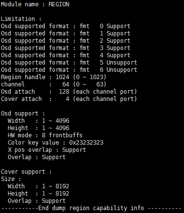
Fig 15‑1
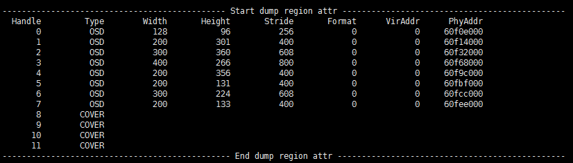
Fig 15‑2
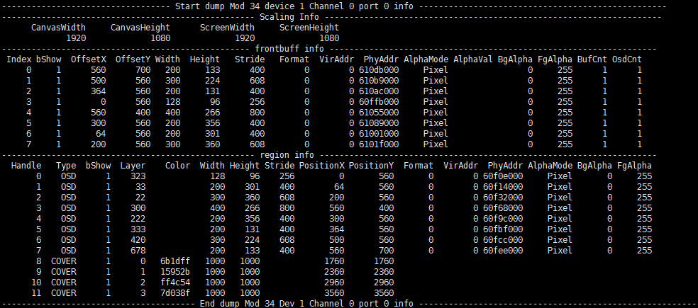
Fig 15‑3
-
Debug info analysis
Record the current RGN usage status and device attributes, and can dynamically obtain information, which is convenient for debugging and testing.
-
Parameter
Table 15‑1
Parameter Description Region capability Region handle The max regions to create are 1024, value: [0~1023] channel The max channels are 64, the channel value: [0~63] Osd attach The max Osds that can be bound to each channel of the output port are 128 Cover attach The max Covers that can be bound to each channel of the output port are 4 Overlay Supported Format Osd supported color format:
0: ARGB1555, align width by 2 pixels
1: ARGB4444, align width by 2 pixels
2: I2, align width by 4 pixels
3: I4, align width by 2 pixels
4: I8
5: RGB565
6: ARGB8888Osd support Osd width value range: 1 ~ 4096
Osd height value range: 1~ 4096
Color key value: Default colorkey value of the system, except for the index format
X pos overlap: Support multiple OSDs overlapping in the x direction.
Overlap: osd supports overlap or not
HW mode: The frontbuffs of Osd, currently set to 8Cover support Osd width value range: 1 ~ 8192
Osd height value range: 1~ 8192
Overlap: Cover supports overlap or notTable 15‑2
Parameter Description Region attr Handle Handle Type Osd or Cover Width Width Height Height Stride Stride Format Color format: [0-6], ARGB1555, ARGB4444, I2, I4, I8, RGB565, ARGB8888 VirAddr Canvas virtual address PhyAddr Canvas physical address Table 15‑3
Parameter Description Channel port Info Frontbuffer info Index Frontbuffer index bShow Show it or not OffsetX X offset OffsetY Y offset Width Width Height Height Stride Stride Format Color format VirAddr Virtual address PhyAddr Physical address AlphaMode Alpha mode, Pixel alpha or constant alpha AlphaVal Constant alpha value BgAlpha In pixle alpha, argb1555 background alpha FgAlpha In pixle alpha, argb1555 foreground alpha BufCnt Front buffers on the channel OsdCnt Number of back buffers for splicing a front buffer on the channel Attach info Handle Bind the region handle Type Bind the region type bShow Show it or not Layer Bind the layer of Cover Color Bind the color value of Cover Width Width Height Height Stride Stride PositionX X offset PositionY Y offset Format Bind the color format of Osd VirAddr Virtual address PhyAddr Physical address AlphaVal Constant alpha value BgAlpha In pixle alpha, argb1555 background alpha FgAlpha In pixle alpha, argb1555 foreground alpha Table 15‑4
Parameter Description Buffer info kmalloc Memory bytes applied for in the Region module. mma alloc Region module applies for the memory bytes through Sys module
15.2. echo
Table 15‑5
| Function | Dump the buffer from specified region |
|---|---|
| Command | echo dumpRgnBuf [Handle] [Path] > /proc/mi_modules/mi_rgn/mi_rgn0 |
| Parameter description | [Handle] region handle |
| [Path] Path to save dump data. The saved content is the canvas of the region. | |
| Example | echo dumpRgnBuf 0 /mnt > /proc/mi_modules/mi_rgn0 ; Generate Rgn0_canvasInfo_fmt0_64X48 in /mnt; It is the canvas data of the region where the dump handle is 0, the color format is ARGB1555, the stride is 64, and the height is 48; The file format is Rgn[Handle]canvasInfo_fmt[Format][Stride]X[Height] [Handle]: region handle. [Format]: Color format, ARGB1555 is 0, ARGB4444 is 1, I2 is 2, I4 is 3. [Stride]: Stride [Height]: Height |
Table 15‑6
| Function | Dump frontbuffer from specifiied channel and port. |
|---|---|
| Command | echo dumpFrontBuf [ModId] [DevId] [ChnID] [PortID] [Path] > /proc/mi_modules/mi_rgn/mi_rgn0 |
| Parameter description | [ModId] Module ID, refer to the module in mi_common_datatype.h to define enumeration values. [DevId] Device ID [ChnID] Channel number [0 ~ 63] [PortID] Port ID [0~3] [Path] Path to save dump data. 0 ~ 2 files will be generated according to the actual frontbuffers currently used. |
| Example | echo dumpFrontBuf 34 1 0 0 /mnt > /proc/mi_modules/mi_rgn/mi_rgn0 Generate Mod34_Dev1_Chn0_Port0_frontbuf0_fmt0_64X48 in /mnt. It is the data of the frontbuffer whose dump channel is 0, the output port is port 34, and the index is 0, the color format is ARGB1555, the stride is 64, and the height is 48 File format Mod[ModId]Dev[DevId]_Chn[Channel]_Port[Port]_frontbuf [Index]_fmt[Format][Stride]X[Height] [ModId] Output module ID. [DevId] Output device ID [Channel] Channel ID. [Port] Output port. [Index] frontbuffer index. [Format] Color format, ARGB1555 is 0, ARGB4444 is 1, I2 is 2, I4 is 3. [Stride] Stride [Height] Height |
Table 15‑7
| Function | get region capability info |
|---|---|
| Command | echo getcap > /proc/mi_modules/mi_rgn/mi_rgn0 |
| Parameter description | None |
| Example | None |
Table 15‑8
| Function | Get created region info |
|---|---|
| Command | echo dumprgn > /proc/mi_modules/mi_rgn/mi_rgn0 |
| Parameter description | None |
| Example | None |
Table 15‑9
| Function | Get channel and port info |
|---|---|
| Command | echo dumpchport > /proc/mi_modules/mi_rgn/mi_rgn0 |
| Parameter description | None |
| Example | None |
Table 15‑10
| Function | Get memory usage info |
|---|---|
| Command | echo bufcnt > /proc/mi_modules/mi_rgn/mi_rgn0 |
| Parameter description | None |
| Example | None |
Table 15‑11
| Function | Enable/Disable a gwin |
|---|---|
| Command | echo setDispOnOff [ModId] [DevId] [ChnID] [PortID] [Idx] [OnOff] > /proc/mi_modules/mi_rgn/mi_rgn0 |
| Parameter description | [ModId] Module ID, refer to the module in mi_common_datatype.h to define enumeration values. [DevId] device ID [ChnID] Channel number [0 ~ 63] [PortID] Port ID [0~3] [Idx] The gwin number displayed by the osd on the current channel. [OnOff] 0: OFF; 1: ON. |
| Example | echo setDispOnOff 34 1 0 0 0 0 > /proc/mi_modules/mi_rgn/mi_rgn0 |
Table 15‑12
| Function | Force to update the back buffer of osd |
|---|---|
| Command | echo forceUpdate [handle] > /proc/mi_modules/mi_rgn/mi_rgn0 |
| Parameter description | [handle] Osd hander. |
| Example | echo forceUpdate 0 > /proc/mi_modules/mi_rgn/mi_rgn0 |
Table 15‑13
| Function | Set the number of front buffers to be displayed |
|---|---|
| Command | echo setFbListMaxCnt [ModId] [DevId] [ChnID] [PortID] [SetByUsr] [Cnt] > /proc/mi_modules/mi_rgn/mi_rgn0 |
| Parameter description | [ModId] Module ID, refer to the module in mi_common_datatype.h to define enumeration values. [DevId] device ID [ChnID] Channel number [0 ~ 63] [PortID] Port ID [0~3] [SetByUsr] Set by user or not, 1: Y; 0: N, default by system; [Cnt] It it is set by user, front buffer is used to display the number, after this setting, you can find it in BufCnt of Frontbuffer info |
| Example | echo setFbListMaxCnt 34 1 0 0 1 3 > /proc/mi_modules/mi_rgn/mi_rgn0 |
16. VDEC
16.1. cat
-
Debug info
# cat /proc/mi_modules/mi_vdec/mi_vdec0
Fig 16‑1
-
Debug info analysis
Use Private Vdec0 Info to divide the print info into two parts. One part is common info, and the other part is vdec module info.
It mainly records the usage and config attributes of the decoding channel, which can be used to check the attribute config and the working status of the current channel, it is convenient for debugging.
-
Parameter
Table 16-1
parameter Description DEV Info DevID Decoding device ID. UUID Chip identification code. MaxChnNum Max decoding channels. bDisableLowLatency Disable the low-latency switch for B-frame decoding. It is enabled by default, that is, only IP frame decoding is supported. Y: Disable the low-latency; N: enable the low-latency. CHN ATTR Info ChnID Channel ID. CodecType Decoding protocol type; 0: H264; 1: H265; 2: JPEG. Width Max width of decoded image. Height Max height of decoded image. BufSize VDEC code stream buffer size, unit: byte. VideoMode Code stream sending mode. STREAM: Send by stream; FRAME: Send by frame. DpbBufMode DPB buffer mode; INPLACE1: A decoded image buffer; INPLACE2: Two decoded image buffers; NORMAL: Normal mode, it cannot save frame buffer. RefFrmNum Max reference frames, JPEG channel is invalid. CHN PARAM Info ChnID Channel ID. bCusPolicy For the wrong macro block, the user decides on or off. Y: Turn on user settings; N: Turn off user settings, which is the default value. ErrMBDropThrd Error mcro block drop frame threshold. DisplayMode Display mode. 0: Preview mode, output without referring to PTS. 1: Playback mode, output referring to PTS. Scale & Crop Info ChnID Channel ID. bScale Scale or not. Y: Enable; N: Disable. ScaleW Scale width. ScaleH Scale height. bCrop Crop or not. Y: Enable; N: Disable. CropX Crop X. CropY Crop Y. CropW Crop width. CropH Crop height. Decode Frame Info ChnID Channel ID. DecW Decode width. DecH Decode height. DispW Display width. DispH Display height. LinearFrmCnt Linear frame buffers count. Output Frame Info ChnID Channel ID. bTileMode Tile mode. Y: Enable; N: Disable. TileFormat Tile format. Only support 128x64. Width Output image width. Height Output image height. Stride Output image stride. PixelFmt Output image pixel format. CHN STATE ChnID Channel ID. bStart Whether the decoder starts to receive the code stream. DecState Decoder status. 1: Enable the decoder; 2: Initialize the decoder; 3: Wait for the init to complete; 4: Register frame buffer 5: Decoding; 6: Disable the decoder. SendCnt Count the times that Api sent the code stream successfully. SendStrmSize The total data of the code stream successfully sent by Api. LeftStrmBytes The bytes to be decoded in the stream buffer. DecFrmCnt The decoded frames in the stream buffer. fps Decode frame rate. CHN STATE ChnID Channel ID. Start Times of starting decoding. Get Get the times decoded output information. Drop Times of dropping frames. Run Times of returning running status. SeqChange Times of sequence switching. InitSeq Interruptions of the initialization sequence. VlcInsuff Insufficient Vlc buffer interrupts. FrmDone Interruptions of Successfully decoding. ISR STATE IsrCnt Count the interruptions times. InitSeq Interruptions of the initialization sequence. VlcInsuff Insufficient Vlc buffer interrupts. FrmDone Interruptions of Successfully decoding. UnderRun Interruptions being decoding. HwTimeout HW timeout interruptions. Other Other interruptions.
16.2. echo
Table 16-2
| Function | Set print mode. |
|---|---|
| Command | echo setprint [Mode] [Level] > /proc/mi_modules/mi_vdec/mi_vdec0 |
| Parameter description | [Mode] log print mode; 0: Output log to kmsg; 1: Output log to serial port. [Level] Print log level; 0: Print ERROR info; 1: Print WARNING and ERROR info; 2: Print INFO, WARNING and ERROR info. |
| Example | echo SetPrint 0 0 > /proc/mi_modules/mi_vdec/mi_vdec0 ; output Log to kmsg, and print ERROR. |
Table 16-3
| Function | Save the code stream written in the buffer to a file. |
|---|---|
| Command | echo dumpbs [ChnID] [Path] > /proc/mi_modules/mi_vdec/mi_vdec0 |
| Parameter description | [ChnID] Channel ID [0~31] [Path] Enter off to stop storing the code stream. |
| Example | echo dumpbs 0 /mnt/dump/ > /proc/mi_modules/mi_vdec/mi_vdec0 ; Channel 0, output in order of display |
Table 16-4
| Function | Save the output YUV to a file. |
|---|---|
| Command | echo dumpfb [ChnID] [Path] [FrmCnt] [bDumpAll] [bDetile] > /proc/mi_modules/mi_vdec/mi_vdec0 |
| Parameter description | [ChnID] Channel ID [0~31] [Path] Storage path [FrmCnt] Store YUV frames [bDumpAll] Store Y buffer, UV buffer and YUV buffer [bDetile] 0: Do not detile the YUV to be stored 1: Detile the YUV to be stored |
| Example | echo dumpfb 0 /mnt/dump/ 1 0 1 > /proc/mi_modules/mi_vdec/mi_vdec0 ; Channel 0, the storage path is /mnt/dump/, stores 1 frame, does not save Y buffer and UV buffer separately, and detile the YUV to be stored. |
Table 16-5
| Function | Write code stream buffer to file. |
|---|---|
| Command | echo dumpbsb [ChnID] [Path] > /proc/mi_modules/mi_vdec/mi_vdec0 |
| Parameter description | [ChnID] Channel ID [0~31] [Path] Storage path |
| Example | echo dumpbsb 0 /mnt/dump/ > /proc/mi_modules/mi_vdec/mi_vdec0 ; Channle 0, the storage path is /mnt/dump/ |
Table 16-5
| Function | Enable/Disable flow checkpoint |
|---|---|
| Command | echo flowdbg [Status] > /proc/mi_modules/mi_vdec/mi_vdec0 |
| Parameter description | [Status] on/off |
| Example | echo flowdbg on > /proc/mi_modules/mi_vdec/mi_vdec0 ; Enbale vdec flow checkpoint, and then enter cat /proc/mi_modules/mi_vdec/mi_vdec0 to view the checkpoints of multiple functions in vdec procfs |
Table 16-6
| Function | Enable/Disable the drop frame switch |
|---|---|
| Command | echo dropoutbuf [Status] > /proc/mi_modules/mi_vdec/mi_vdec0 |
| Parameter description | [Status] on/off |
| Example | echo dropoutbuf on > /proc/mi_modules/mi_vdec/mi_vdec0 ; Drop the frame buffer to be output |
| Function | Enable/Disable the vdec performance statistics switch |
| Command | echo setperf [Status] > /proc/mi_modules/mi_vdec/mi_vdec0 |
| Parameter description | [Status] on/off |
| Example | echo setperf on > /proc/mi_modules/mi_vdec/mi_vdec0 ; Enable the vdec performance statistics switch, and then enter cat /proc/mi_modules/mi_vdec/mi_vdec0 to view the current decoding time and other data in vdec procfs. |
17. WARP
17.1. cat
-
Debug info
# cat /proc/mi_modules/mi_warp/mi_warp0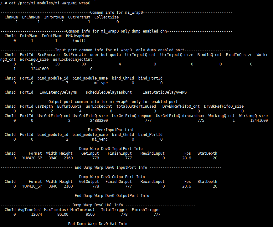
Fig 17‑1
-
Debug info analysis
Printing is divided into common info and warp module info.
It mainly records the usage and port status of each channel of the warp device, which can be used to check the attribute config and the working status of the current channel, it is convenient for debugging.
-
Parameter
Table 17‑1
Parameter Description Dev InputPort Info ChnId Channel ID. Format Pixel format: YUV422_YUYV; YUV420_SP; Unknown. Width Frame width. Height Frame height. GetInput Buffers received by InputPort. FinishInput Buffers finished by InputPort, including processed and dropped frames. RewindInput Buffers rewinded by InputPort. Fps Frame rate on InputPort. Sampling according to the two-frame time interval, first calculate the average time interval, and then calculate the frame rate. StatDepth Sample size. Value range: (1~100). Dev OutputPort Info ChnId Channel ID. Format Pixel format: YUV422_YUYV; YUV420_SP; Unknown. Width Frame width. Height Frame height. GetOutput Buffers received by OutputPort. FinishOutput Buffers processed by OutputPort. RewindOutput Buffers rewinded by OutputPort. Fps Frame rate on OutputPort. Sampling according to the two-frame time interval, first calculate the average time interval, and then calculate the frame rate. StatDepth Sample size. Value range: (1~100), the default is 20. Dev Hal Info ChnId Channel ID. AvgTime The average time for Hal to execute a single trigger. Unit: us. MaxTime The max time for Hal to execute a single trigger. Unit: us. MinTime The min time for Hal to execute a single trigger. Unit: us. TotalTrigger Hal layer total triggers. FinishTrigger Hal layer finished triggers.
17.2. echo
Table 17‑2
| Function | Dump module config file. |
|---|---|
| Command | echo dump_table2file [ChnID] [BinType] [BinPath] > /proc/mi_modules/mi_warp/mi_warp0 |
| Parameter description | [ChnID] Channel ID 0 [BinType] Bin file type 0 -> Bounding Box Table ; The dumped file name is Warp_BbTable.bin 1 -> Displayment Table; The dumped file name is Disp_absolute.bin or Disp_relative.bin (Generate different files according to the type of disp_table in warpConfig). [BinPath] Bin file path |
| Example | echo 0 0 /mnt/warp > /proc/mi_modules/mi_vdec/mi_vdec0 Channel 0, Bin file type is Bounding Box, path is /mnt/warp. Generate the file Warp_BbTable.bin in the /mnt/warp. |
Table 17‑3
| Function | Dump input/output port frame rate. |
|---|---|
| Command | echo dump_fps > /proc/mi_modules/mi_warp/mi_warp0 |
| Parameter description | None. |
| Example | None. |
Table 17‑4
| Function | Statistic input/output port data frame status. |
|---|---|
| Command | echo dump_frameCnt > /proc/mi_modules/mi_warp/mi_warp0 |
| Parameter description | None. |
| Example | None. |
Table 17‑5
| Function | Statistic hal time consumption. |
|---|---|
| Command | echo dump_halTimeConsume > /proc/mi_modules/mi_warp/mi_warp0 |
| Parameter description | None. |
| Example | None. |
Table 17‑6
| Function | Set the statistical sample size. |
|---|---|
| Command | echo dump_SetStatDepth [Depth] > /proc/mi_modules/mi_warp/mi_warp0 |
| Parameter description | [Depth] Sample size. |
| Example | echo dump_SetStatDepth 30 /mnt/warp > /proc/mi_modules/mi_vdec/mi_vdec0 ; Set the statistical sample size to 30. Count the pts difference between two frames and put it into the sample set, up to 30, when it is less than 30, calculate fps according to the actual sample; when it reaches 30, calculate fps according to the 30 pts difference. |
18. Sensor
18.1. cat
-
Debug info
# cat /proc/mi_modules/mi_sensor/mi_sensor0
Fig 18‑1
-
Debug info analysis
Record the current sensor usage status and attributes, and can dynamically obtain information, which is convenient for debugging and testing.
-
Parameter
Table 18‑1
Parameter Description Pad info Padid Sensor pad id Planemode Plane mode switch bEnable Sensor enable bmirror Mirror flip bflip Flip vertically fps Frame rate ResCnt Resolutions supported by Sensor Intfmode Interface Protocol Hdrmode Hdr hw mode Planecnt Plane channels Mipiattr Yuvorder Yuv data order Hdrhwmode Hdr hw mode Datafmt Data format, yuv/rgb HdrVchNum HDR virtual channels supported by Sensor HsyncMode 0: Sync the previous one
1: Sync the next oneLaneNum Supported signal lines for simultaneous data transmission LPackType0 Data packing format 0 LPackType1 Data packing format 1 samDelay Delay skipping the data header BT656Attr BitSwap Data arrangement direction ClkEdge Sample clock mode Multinum Complex mode channels HPol H sync polarity PcPol Pclk polarity VPol V sync polarity HDelay H sync delay VDelay V sync delay PcDelay Pclk delay ParallelAttr HPol H sync polarity PcPol Pclk polarity VPol V sync polarity HDelay H sync delay VDelay V sync delay PcDelay Pclk delay Res Sensor 支持的分辨率信息 strResDesc Resolution CropX/CropY/CropW/CropH Crop parameter OutW/OutH Output width/height MaxFps/MinFps Max/Min frames rate Cur Resolution info currently in use Table 18‑2
Parameter Description Plane info Padid pad id Planeid Plane id SnrName Sensor name BayerId Bayer id ePixPrec Pixel accuracy (12bpp,10bpp ….) eHdrSrc HDR Channel ID CropX/CropY/CropW/CropH Crop parameter
18.2. echo
-
Debug info
# echo help > /proc/mi_modules/mi_sensor/mi_sensor0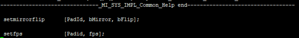
Fig 18‑2 Commands
Table 18‑3
Function Set the sensor flip Command echo setmirrorflip [PadId, bMirror, bFlip] > /proc/mi_modules/mi_sensor/mi_sensor0 Parameter description PadId: pad id bMirror: Mirror flip bFlip: Flip up and down Example echo setmirrorflip 0 1 0 > /proc/mi_modules/mi_sensor/mi_sensor0 Table 18‑4
Function Set the sensor frame rate Command echo setfps [Padid, fps] > /proc/mi_modules/mi_sensor/mi_sensor0 Parameter description PadId: pad id fps: Frame rate Example echo setfps 0 15 > /proc/mi_modules/mi_sensor/mi_sensor0
19. ISP
19.1. cat
-
Debug info
# cat /proc/mi_modules/mi_isp/mi_isp0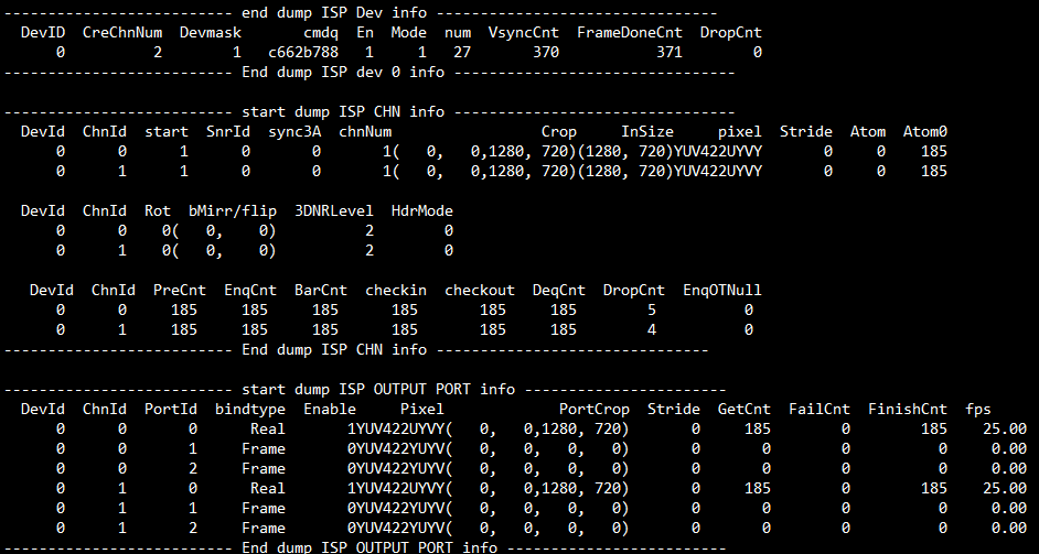
Fig 19-1
-
Debug info analysis
Record the current ISP usage status and related attributes, and can dynamically obtain information, which is convenient for debugging and testing.
-
Parameter
Table 19-1
Parameter Description ISP Dev info DevId Isp Dev Id CreChnNum Chn number DevMask Stitch Dev Mask cmdq Cmdq pointer En ISR interrupt enable flag Mode ISR interrupt mode num ISR ID VsyncCnt ISR VsyncCnt FrameDoneCnt ISR Frame Done Cnt DropCnt ISR Frame Drop Cnt Table 19-2
Parameter Description ISP Chn info DevId Isp Dev Id ChnId Isp Chn Id start Chn Start Flag SnrId Bind sensorId Sync3A Sync 3A type chnNum Muti chn Num Crop Input Crop Size InSize Input Size pixel Input pixel format Stride Input Buffer Stride Atom Bottom buffers Atom0 There is no buffer at the bottom after the buffer is released Rot Rotation angle bMirror/Flip mirror/flip 3DNRLevel 3DNR Level HdrMode HDR mode PreCnt/EnqCnt/BarCnt
/checkin/checkout/DeqCnt/DropCntCallback execution times aEnqOTNull When Enq, OutBuffer is statistics of Null Table 19-3
Parameter Description ISP OutPut Port info DevId Isp Dev Id ChnId Isp Chn Id PortID Port Id Bindtype Binding mode with post-level Enable Port enable flag Pixel Port output pixel format PortCrop output Crop Size Stride Output Stride GetCnt Get number of OutPut buffer Failcnt Get the times of OutPut buffer failure FinishCnt Processed output buffers fps Output port frame rate
19.2. Echo
echo help > /proc/mi_modules/mi_isp/mi_isp0
Table 19-4
| Function | Print all functions/line/time used by the channel locks |
|---|---|
| Command | echo debugmutex > /proc/mi_modules/mi_isp/mi_isp0 |
| Parameter description | None |
| Example | None |
Table 19-5
| Function | Stop specifing channel |
|---|---|
| Command | echo stopchnl [ChnID] [ON/OFF] > /proc/mi_modules/mi_isp/mi_isp0 |
| Parameter description | [ChnId] :Channel ID [ON/OFF] ON:stop chn OFF:start chn |
| Example | echo stopchnl 0 ON > /proc/mi_modules/mi_isp/mi_isp0 |
Table 19-6
| Function | Dump the output data of the selected channel and save it in /path |
| Command | echo dumptaskfile [chnid, Cnt, /path/, bOnlyDumpResChange, bdumpport] > /proc/mi_modules/mi_isp/mi_isp0 |
| Parameter description | Chnid: channel id |
| Cnt: dump Num | |
| Path: Store dump files | |
| bOnlyDumpResChange: Blurred images may be generated when switching resolutions. The dump command and switching resolution operations are not easy to perform together. You can set this parameter first, and then switch the resolution. After the program recognizes it, the buffer after the resolution change will be dumped. (Optional) | |
| Bdumpport: Only dump a certain portid, the default is to dump all the ports in the output. (Optional) | |
| Example | echo dumptaskfile 0 1 /mnt > /proc/mi_modules/mi_isp/mi_isp0 |
Table 19-7
| Function | Set the atomvalue of Dev |
|---|---|
| Command | echo setatom [AtomValue] > /proc/mi_modules/mi_isp/mi_isp0 |
| Parameter description | AtomValue: Driver's buffer max value in input realtime mode |
| Example | echo setatom 3 > /proc/mi_modules/mi_isp/mi_isp0 Note: Increase the atom when the bottom layer is stuck, add a buffer to the driver, and re-trig to see if it recovers, or increase it when the frame is dropped to see if the frame can be full. |
Table 19-8
| Function | Clear the input/output/done of the specified channel portbuffer |
|---|---|
| Command | echo clearbuf [chnid, portid bClearInput, bclearoutput, bcleardonebuff] > /proc/mi_modules/mi_isp/mi_isp0 |
| Parameter description | Chnid: channel id Portid: port id bClearInput: Clear the input buffer bclearoutput: Clear the output buffer bcleardonebuff: Clear the completed buffer |
| Example | echo clearbuf 0 0 1 0 0 > /proc/mi_modules/mi_isp/mi_isp0 |
Table 19-9
| Function | Set debug level |
|---|---|
| Command | echo debuglv [level] >/proc/mi_modules/mi_isp/mi_isp0 |
| echo debuglv [chnid][level] >/proc/mi_modules/mi_isp/mi_isp0 | |
| Parameter description | Chnid: channel id Level: (3) Single level parameter: 1:isp api,2:flow,4:check irq done (4) Double parameter: 1:check buffer,2:check loop,4:check frame pts,8:check fence done,16:check func time,32:check sidebandmsg,64:check zoominfo |
| Example | echo debuglv 4 > /proc/mi_modules/mi_isp/mi_isp0 //Open check irq done related MI print echo debuglv 0 3 > /proc/mi_modules/mi_isp/mi_isp0 //Open channel0 level3 printing to print buffer info and loop info |
Table 19-10
| Function | Drop frame count |
|---|---|
| Command | echo skipframe [chnid, skipnum] > /proc/mi_modules/mi_isp/mi_isp0 |
| Parameter description | Chnid: channel id skipnum: drop frame count |
| Example | echo skipframe 0 60 > /proc/mi_modules/mi_isp/mi_isp0 |
Table 19-11
| Function | Protect outputport buffer |
|---|---|
| Command | echo protectport [chnid portid clientid ben] > /proc/mi_modules/mi_isp/mi_isp0 |
| Parameter description | Chnid: channel id Portid: port id Clientid: isp:0x23, LDC:0x0e, scl(0,1,2):0x19, 0x1c, 0x1d ben: Enable |
| Example | echo protectport 0 0 0x23 1 > /proc/mi_modules/mi_isp/mi_isp0 //Protect isp in channel0 pass0 port0 |
Table 19-12
| Function | Consume the buffer cached in Bind Q |
|---|---|
| Command | echo clearbindq [chnid bclear] > /proc/mi_modules/mi_isp/mi_isp0 |
| Parameter description | Chnid: channel id bclear: 是否clear |
| Example | echo clearbindq 0 0 1 > /proc/mi_modules/mi_isp/mi_isp0 //clear channel0 pass0 bindQ Consume the buffer cached in Bind Q. The ISP BindQ is full and the front-end cannot get the buffer, and judge whether the ISP is too slow. Clear bindQ and observe whether it will accumulate. If it is, the ISP is too slow, if not, the previous exception is not consumed. |
Table 19-13
| Function | Set the print frame rate, print if it is lower than this value |
|---|---|
| Command | echo fpsth [chnid portid fpsint fpsfloat] > /proc/mi_modules/mi_isp/mi_isp0 |
| Parameter description | Chnid: channel id Portid: port id fpsint: Frame rate integer bits fpsfloat: Frame rate decimal bits |
| Example | echo fpsth 0 0 30 30 > /proc/mi_modules/mi_isp/mi_isp0 // Print the fps which is less than 30.30 in channel0 port0 |
Table 19-14
| Function | Enabling port or not |
|---|---|
| Command | echo enableport [chnid, portid, bEn] > /proc/mi_modules/mi_isp/mi_isp0 |
| Parameter description | Chnid: channel id Portid: port id bEn: 1/0 |
| Example | echo enableport 0 0 1 > /proc/mi_modules/mi_isp/mi_isp0 |
20. SCL
20.1. cat
-
Debug info
# cat /proc/mi_modules/mi_scl/mi_scl0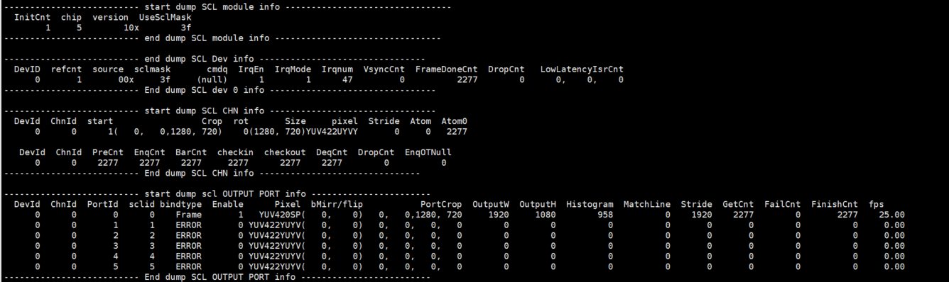
Fig 20-1
-
Debug info analysis
Record the current scaler usage status and related attributes, and can dynamically obtain information, which is convenient for debugging and testing.
-
Parameter
Table 20-1
Parameter Description module info InitCnt The number of connected module occurrences chip Chip index version Chip version UseSclMask Module scaler usage Table 20-2
Parameter Description Device Info DevID Device ID refcnt The number of repeated dev creations source Input source sclmask Scaler id used by the device cmdq Cmdq pointer IrqEn IRQ enable status IrqMode IRQ mode Irqnum IRQ ID VsyncCnt ISR vsync Cnt FrameDoneCnt ISR Frame Done Cnt DropCnt IRQ Frame Drop or Double Vsync LowLatencyIsrCnt Low Lantency Mode Match Line IRQ Cnt Table 20-3
Parameter Description Channel Info DevId Device id ChnId Channel ID start Channel start or not Crop Channel Crop position Rot Rotation angle Size input width/height pixel Input Pixel format Stride Input buffer stride Atom Bottom buffers Atom0Cnt There is no buffer at the bottom after the buffer is released PreCnt/EnqCnt/BarCnt/checkin/
checkout/DeqCnt/DropCntCallback execution times EnqOTNull Statistics that OutBuffer is Null in Enq Table 20-4
Parameter Description Outputport Info DevId Device id ChnId Channel ID PortId Port ID sclid scaler ID bindtype 0: Real Time mode
1: Ring mode
2: frame modeEnable Enable Pixel Output pixel format bMirr/flip Port mirror/flip PortCrop Port cropping range OutputW /OutputH Output width/height Histogram Scl Histogram MatchLine Low Lantency Mode Match Line Cnt Stride Output buffer stride, a row of pixel bytes GetCnt Get the outputbuffer number FailCnt Get the times of outputbuffer failure FinishCnt Processed output buffers fps Output port frame rate
20.2. echo
# echo help > /proc/mi_modules/mi_scl/mi_scl0
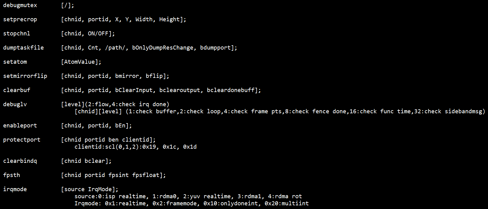
Fig 20-2 Echo help commands
Table 20-5
| Function | Print all functions/line/time used by the channel locks |
|---|---|
| Command | echo debugmutex > /proc/mi_modules/mi_scl/mi_scl0 |
| Parameter description | None |
| Example | None |
Table 20-6
| Function | Set the crop parameters of each scl port, directly set to the driver, without going through the MI process |
|---|---|
| Command | echo setprecrop [chnid portid X Y Width Height] > /proc/mi_modules/mi_scl/mi_scl0 |
| Parameter description | Chnid: channel id Portid: port id X,Y,width,height: crop range |
| Example | echo setprecrop 0 0 0 0 800 200 > /proc/mi_modules/mi_scl/mi_scl0 |
Table 20-7
| Function | After the bottom layer buffer is processed, close the channel and no longer trig the bottom layer. |
|---|---|
| Command | echo stopchnl [chnid, ON/OFF] > /proc/mi_modules/mi_scl/mi_scl0 |
| Parameter description | Chnid: channel id ON/OFF: open/close stopchannel |
| Example | echo stopchnl 0 ON > /proc/mi_modules/mi_scl/mi_scl0 |
| echo stopchnl 0 OFF > /proc/mi_modules/mi_scl/mi_scl0 |
Table 20-8
| Function | Dump the output data of the selected channel and save it in /path |
|---|---|
| Command | echo dumptaskfile [chnid, Cnt, /path/, bOnlyDumpResChange, bdumpport] > /proc/mi_modules/mi_scl/mi_scl0 |
| Parameter description | Chnid: channel id Cnt: dump number Path: The path to store the dumped files bOnlyDumpResChange: Blurred images may be generated when switching resolutions. The dump command and switching resolution operations are not easy to perform together. You can set this parameter first, and then switch the resolution. After the program recognizes it, the buffer after the resolution change will be dumped. (Optional) Bdumpport: Only dump a certain portid, the default is to dump all the ports in the output. (Optional) |
| Example | echo dumptaskfile 0 2 /tmp > /proc/mi_modules/mi_scl/mi_scl0 |
Table 20-9
| Function | Set the atomvalue of pass |
|---|---|
| Command | echo setatom [AtomValue] > /proc/mi_modules/mi_scl/mi_scl0 |
| Parameter description | AtomValue: Driver's maximum buffer number |
| Example | echo setatom 3 > /proc/mi_modules/mi_scl/mi_scl0 Note: Increase the atom when the bottom layer is stuck, add a buffer to the driver, and re-trig to see if it recovers, or increase it when the frame is dropped to see if the frame can be full. |
Table 20-10
| Function | Set the output screen of the channel and port to see if it can be flipped |
|---|---|
| Command | echo setmirrorflip [chnid, portid, bmirror, bflip] > /proc/mi_modules/mi_scl/mi_scl0 |
| Parameter description | Chnid: channel id Portid: port id bmirror: Mirror flip bflip: Flip up and down |
| Example | echo setmirrorflip 0 0 1 0 > /proc/mi_modules/mi_scl/mi_scl0 Mirror flip |
Table 20-11
| Function | Clear the input/output/done buffer of the specified channel port |
|---|---|
| Command | echo clearbuf [chnid, portid bClearInput, bclearoutput, bcleardonebuff] > /proc/mi_modules/mi_scl/mi_scl0 |
| Parameter description | Chnid: channel id Portid: port id bClearInput: Clear the input buffer bclearoutput: Clear the output buffer bcleardonebuff: Clear the completed buffer |
| Example | echo clearbuf 0 0 1 0 0 > /proc/mi_modules/mi_scl/mi_scl0 |
Table 20-12
| Function | Set debug level |
|---|---|
| Command | echo debuglv [level] >/proc/mi_modules/mi_scl/mi_scl0 |
| echo debuglv [chnid][level] >/proc/mi_modules/mi_scl/mi_scl0 | |
| Parameter description | Chnid: channel id Level: (1) Single level parameter: 2:flow, 4:check irq done (2) Double parameter: 1:check buffer,2:check loop,4:check frame pts,8:check fence done,16:check func time,32:check sidebandmsg |
| Example | echo debuglv 4 > /proc/mi_modules/mi_scl/mi_scl0 //Open check irq done related MI print echo debuglv 0 3 > /proc/mi_modules/mi_scl/mi_scl0 //Open channel0 level3 printing to print buffer info and loop info |
Table 20-13
| Function | Enabling port or not |
|---|---|
| Command | echo enableport [chnid, portid, bEn] > /proc/mi_modules/mi_scl/mi_scl0 |
| Parameter description | Chnid: channel id Portid: port id bEn: 1/0 |
| Example | echo enableport 0 0 1 > /proc/mi_modules/mi_scl/mi_scl0 |
Table 20-14
| Function | Protect outputport buffer |
|---|---|
| Command | echo protectport [chnid portid ben clientid] > |
| /proc/mi_modules/mi_scl/mi_scl0 | |
| Parameter description | Chnid: channel id Portid: port id ben: enable Clientid: scl(0,1,2):0x19, 0x1c, 0x1d |
| Example | echo protectport 0 0 1 0x19> /proc/mi_modules/mi_scl/mi_scl0 |
| //Protect scl0 of channel0 port0 |
Table 20-15
| Function | Consume the buffer cached in Bind Q |
|---|---|
| Command | echo clearbindq [chnid bclear] > /proc/mi_modules/mi_scl/mi_scl0 |
| Parameter description | Chnid: channel id bclear: clear or not |
| Example | echo clearbindq 0 1 > /proc/mi_modules/mi_scl/mi_scl0 //clear channel0 bindQ Consume the buffer cached in Bind Q. The scl BindQ is full and the front-end cannot get the buffer, and judge whether the scl is too slow. Clear bindQ and observe whether it will accumulate. If it is, the scl is too slow, if not, the previous exception is not consumed. |
Table 20-16
| Function | Set the print frame rate, print if it is lower than this value |
|---|---|
| Command | echo fpsth [chnid portid fpsint fpsfloat] > /proc/mi_modules/mi_scl/mi_scl0 |
| Parameter description | Chnid: channel id Portid: port id fpsint: Frame rate integer bits fpsfloat: Frame rate decimal bits |
| Example | echo fpsth 0 0 30 30 > /proc/mi_modules/mi_scl/mi_scl0 //Print the fps which is less than 30.30 in channel0 port0 |
Table 20-17
| Function | Set the irq mode of the input source |
|---|---|
| Command | echo irqmode [source irqmode] > /proc/mi_modules/mi_scl/mi_scl0 |
| Parameter description | Source: 0:isp realtime, 1:rdma0, 2:yuv realtime, 3:rdma1, 4:rdma rot Irqmode: 0x1:realtime, 0x2:framemode, 0x10:onlydoneint, 0x20:multiint |
| Example | echo irqmode 0 1 > /proc/mi_modules/mi_scl/mi_scl0 |