外设
1. 概述
SSC8x39支持的外设包括GPIOs, PWM, UART, Timers, SPI, I2C, IR, ADC, I2S等等。
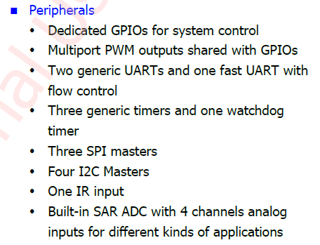
图 ‑1 外设
2. GPIO
2.1. GPIO Index
GPIO API头文件Mercury5\proj\sc\driver\drv\io\pub\drv_gpio.h
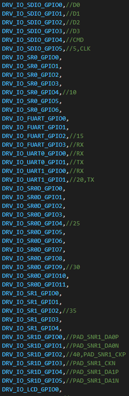
图 2‑1 头文件中的定义
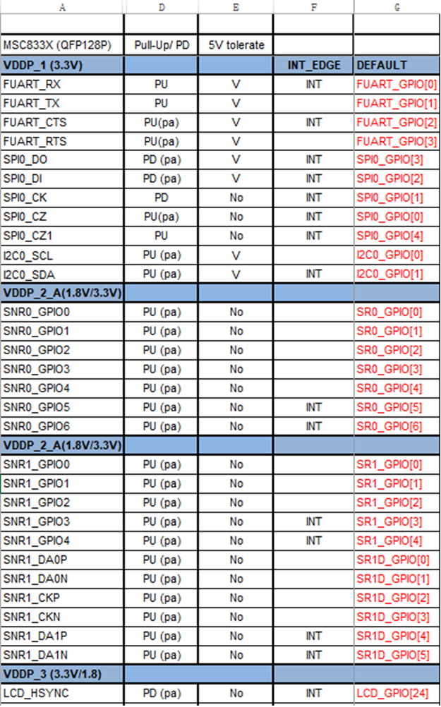
图 2‑2 HW Checklist.xls的PIN脚复用定义
通过原理图中的PIN脚命名在HW Checklist.xls中查看对应GPIO命名确定需要使用GPIO宏定义。
2.2. GPIO API
-
void DrvGPIOPadSet(DrvGPIOSe eGPIOIndex, bool bEnable)
-
配置GPIO复用功能
-
bEnable = TRUE时打开此PIN脚的GPIO功能,同时其他复用功能被关闭
-
-
void DrvGPIOOutputEnable(DrvGPIOSe eGPIOIndex,bool bEnable)
-
GPIO输出使能
-
bEnable = TRUE时此GPIO输出模式使能,FALSE时此GPIO输入模式使能
-
-
bool DrvGPIOGetLevel(DrvGPIOSe eGPIOIndex)
-
读取GPIO输入Level
-
输入高电平返回TRUE,输入低电平返回FALSE
-
-
bool DrvGPIOGetDirection(DrvGPIOSe eGPIOIndex)
-
获取GPIO输入输出模式
-
返回TRUE表示此GPIO为输出模式,返回FALSE表示此GPIO为输入模式
-
-
void DrvGPIOSetOutputData(DrvGPIOSe eGPIOIndex,bool bHL)
-
设定GPIO输出Level
-
bHL = TRUE,输出高电平,bHL = FALSE,输出低电平
-
-
bool DrvGPIOEnableINT(DrvGPIOSe eGPIOIndex, bool bEnable, PfnIntcISR pfCB)
-
GPIO中断使能
-
bEnable = TRUE,使能GPIO中断
-
pfCB 为中断处理回调函数
-
-
bool DrvGPIOSetPolarity(DrvGPIOSe eGPIOIndex,u8 reverse)
-
GPIO中断触发极性
-
只支持高电平/低电平触发,不支持边沿触发
-
-
bool DrvGPIOEnablePull(DrvGPIOSe eGPIOIndex,u8 bEnable)
- GPIO内部上下拉使能
-
bool DrvGPIOSetPullStatus(DrvGPIOSe eGPIOIndex,u8 bHL)
- GPIO内部上拉/下拉状态设定
-
bool DrvGPIOSetDriving(DrvGPIOSe eGPIOIndex,u8 nLevel)
- GPIO驱动电流能力设定
2.3. GPIO测试
在UART终端敲"io",会列出io可用方法。
/:io
io gpio     -- io gpio [GPIONum] [IN:1/OUT:0] [H:1/L:0]
io gpiodrv  -- io gpiodrv [GPIONum] [Level]
io gpiopull -- io gpiopull [GPIONum] [pull enable] [pull H/L]
io pwm      -- io pwm [PWMIndex] [PadMode] [Freq(Hz)] [shift(%)] [duty(%)] [NOT invert]
GPIONum即GPIO对应的枚举值。
以PAD_FUART_CTS的GPIO输出功能为例,操作如下:
通过HW CheckList.xls和DrvGPIOSe枚举定义,确认PAD_FUART_CTS这个PIN对应枚举DRV_IO_FUART_GPIO2,GPIONum = 15。
输出高电平:
/:io gpio 15 0 1
====GPIO : 15 ,Is Input? : 0, H/L : 0====
输出低电平:
/:io gpio 15 0 0
====GPIO : 15 ,Is Input? : 0, H/L : 1====
查看HW CheckList.xls Pull-Up/Down页确定GPIO是否支持驱动设定,Driving页确定支持的Level,大多数GPIO只支持2挡设定,分别对应nLevel = 1(8mA)/ nLevel = 0(4mA)。
2.4. GPIO应用
-
PAD_FUART_CTS: GPIO输出高/低电平
DrvGPIOPadSet(DRV_IO_FUART_GPIO2, 1); //设置为输出
DrvGPIOOutputEnable(DRV_IO_FUART_GPIO2, 1); //设置为输出使能
在不改变GPIO输入输出状态的情况下,PadSet/OutputEnable只需要Call一次即可。
改变输出电平高低不需要重复做 PadSet/OutputEnable。
DrvGPIOSetOutputData(DRV_IO_FUART_GPIO2, 0); //输出低电平
DrvGPIOSetOutputData(DRV_IO_FUART_GPIO2, 1); //输出高电平
-
PAD_FUART_CTS: GPIO中断(注意:使用GPIO中断功能时需要通过HW CheckList.xls确认此GPIO是否支持中断功能。)
void _GPIOInputISR(void)
{
    //中断处理函数,根据需要决定在中断中处理的业务。
    UartSendTrace("_GPIOInputISR Enter!\n");
}

DrvGPIOPadSet(DRV_IO_FUART_GPIO2,1);
DrvGPIOEnableINT(DRV_IO_FUART_GPIO2,1, _GPIOInputISR);
DrvGPIOSetPolarity(DRV_IO_FUART_GPIO2,0);//设定为低电平触发
3. I2C
头文件Mercury5\proj\sc\driver\drv\bus\pub\drv_bus_i2c.h
I2CErrorCode_e DrvI2cOpen(s32 *pHandle, I2COptions_t *psI2cSettings);
I2CErrorCode_e DrvI2cClose(s32 nHandle);
I2CErrorCode_e DrvI2cWrite(s32 nHandle, void * pDataToWrite, u32 nNbBytes, bool bStopBit);
I2CErrorCode_e DrvI2cRead(s32 nHandle, void * pDataToRead, u32 nNbBytes);
I2CErrorCode_e DrvI2cWriteAndRead(s32 nHandle, void * pDataToWrite, u32 nNbBytesToWrite, void * pDataToRead, u32 nNbBytesToRead);
I2CErrorCode_e DrvI2cOpenSW(u32 nAddress, I2cClockSpeed_e eClkSpeed, IoChipPadNum_e eScl, IoChipPadNum_e eSda, s32 *pHandle);
I2CErrorCode_e DrvI2cAddrWrite(s32 nHandle, u16 nAddress, u16 nDataToWrite, bool bStopBit);
I2CErrorCode_e DrvI2cAddrRead(s32 nHandle, u16 nAddress, u16 *pDataToRead, bool bStopBit);
4. SPI
头文件Mercury5\proj\sc\driver\drv\bus\pub\drv_mspi.h
MSpiErrorCode_e DrvMSpiOpen(MSpiChannel_e *pHandle, MSpiSettings_t *ptMSpiSetting);
MSpiErrorCode_e DrvMSpiClose(MSpiChannel_e nHandle);
MSpiErrorCode_e DrvMSpiWrite(MSpiChannel_e nHandle, void *pDataToWrite, u32 nWriteLen);
MSpiErrorCode_e DrvMSpiRead(MSpiChannel_e nHandle, void *pDataToRead, u32 nReadLen);
MSpiErrorCode_e DrvMSpiReadEx(MSpiChannel_e nHandle, void *pDataToWrite, u32 nWriteLen, void *pDataToRead, u32 nReadLen);
SPI时钟源有108M/54M/12M,DIV有2/4/8/16/32/64/128/256,根据用户设定MSpiSettings t参数nMspiClk,driver自动计算对应Div和时钟源,SPI CLK最大支持54MHz,最小支持46875Hz。
MSPI参数设定结构体:
typedef struct
{
    MSpiChannel_e       eChannel;
    MSpiRWMethod_e      eRWMethod;
    MSpiMode_e          eMSpiMode;
    MSpiPad_e           ePadSelect;
    u32                 nMspiClk;
    MSpi_BufferConfig   sBufferCfg;
} MSpiSettings_t;
| 成员名称 | 描述 |
|---|---|
| eChannel | SPI的Channel,SPI0就是Channel0,SPI1就是Channel1 |
| eRWMethod | SPI读写方式,支持polling or interrupt |
| eMSpiMode | SPI的相位(CPHA)和极性(CPOL)模式 Mode 0 CPOL=0, CPHA=0 Mode 1 CPOL=0, CPHA=1 Mode 2 CPOL=1, CPHA=0 Mode 3 CPOL=1, CPHA=1 |
| ePadSelect | SPI的PadMux,一个SPI Channel可能有多组PIN复用,Padmux参数决定使用哪一组PIN。根据硬件原理图设计查看HW CheckList文档确定参数配置。 |
| nMspiClk | SPI Clk参数,单位Hz |
| sBufferCfg | SPI 读写数据Buffer参数配置 |
MSPI读写Buffer bits参数结构体:
typedef struct
{
    u8 u8WBitConfig[8];      //bits will be transferred in write buffer ,0~7 means 1bit~8bit
    u8 u8RBitConfig[8];      //bits Will be transferred in read buffer ,0~7 means 1bit~8bit
} MSpi_BufferConfig;
| 成员名称 | 描述 |
|---|---|
| u8WBitConfig[8] | MSPI最大支持8Bytes的WriterBuffer,每个Byte的有效数据bits,参数范围07,对应1bit8bit有效数据 |
| u8RBitConfig[8] | MSPI最大支持8Bytes的ReadBuffer,每个Byte的有效数据bits,参数范围07,对应1bit8bit有效数据 |
MSpiErrorCode_e eRtn;
MSpiSettings_t  tSetting;

tSetting.eChannel       = MSPI_CH1;
tSetting.eMSpiMode  = MSPI_MODE0;
tSetting.ePadSelect     = MSPI_PAD1;
tSetting.eRWMethod  = MSPI_RW_METHOD_POLLING;
tSetting.nMspiClk       = 27000000;
for (i = 0 ; i < 8 ; i++) {
    tSetting.sBufferCfg.u8RBitConfig[i] = 7; //Read Buffer有效位数,参数7表示8bit有效
    tSetting.sBufferCfg.u8WBitConfig[i] = 7; //Write Buffer 有效位数,参数7表示8bit有效
}
eRtn = (DrvMSpiOpen(&eSPIHandle,&tSetting));
if(MSPI_PROC_DONE != eRtn)
    UartSendTrace(" MSpi Open err  %d \n", eRtn);

//SPI Read Data
{
    int i;
    MSpiErrorCode_e eRtn;

    u8 aReadBuf[8] = {0};
    memset(aReadBuf, 0x0, sizeof(aReadBuf));

    eRtn = DrvMSpiRead(eSPIHandle, aReadBuf, sizeof(aReadBuf));
    UartSendTrace("=== DrvMSpiRead res = [%d] ===\r\n", eRtn);
    for(i = 0 ; i < sizeof(aReadBuf) ; i++)
    {
        UartSendTrace(" %x ", aReadBuf[i]);
    }
    UartSendTrace("\r\n");
}

//SPI Write Data
{
    MSpiErrorCode_e eRtn;
    u8 aWriteBuf[8] = {0};

    memset(aWriteBuf, 0x0, sizeof(aWriteBuf));
    aWriteBuf[0] = 0x00;
    aWriteBuf[1] = 0x01;
    aWriteBuf[2] = 0x02;
    aWriteBuf[3] = 0x03;
    aWriteBuf[4] = 0x04;
    aWriteBuf[5] = 0x05;
    aWriteBuf[6] = 0x06;
    aWriteBuf[7] = 0x07;

    eRtn = DrvMSpiWrite(eSPIHandle, aWriteBuf, sizeof(aWriteBuf));
    UartSendTrace("=== DrvMSpiWrite res = [%d] ===\r\n", eRtn);
}
5. UART
头文件Mercury5\proj\sc\driver\drv\uart\inc\drv_uart.h
s32 uart_Open( Uart_Num_t uart_num, Uart_cfg_t *uart_cfg );
void uart_SetRate(Uart_Num_t uart_num, vm_v24_Rate_t Rate );
void uart_SetFraming( Uart_Num_t uart_num, vm_v24_Framing_t Framing );
s32 uart_Write( Uart_Num_t uart_num, u8 *string,  u32 length);
s32 uart_Read( Uart_Num_t uart_num, u8 *string,  u32 length);
s32 uart_GetRxFifoLevel( Uart_Num_t uart_num);
bool uart_IsTxFifoEmpty( Uart_Num_t uart_num);
s32 uart_ClearRxBuffer( Uart_Num_t uart_num);
UART配置参数结构体:
typedef struct {
    vm_v24_SerialLength_t       length;           ///< length in number of bits
    vm_v24_SerialParity_t       parity;           ///< parity
    vm_v24_SerialStop_t         stop;              ///< stop bit
    vm_v24_Rate_t           rate;              ///< bit rate
    vm_v24_FlowControl_t      RxFlowCtrlMethod; ///< type of Rx flow control
    vm_v24_FlowControl_t      TxFlowCtrlMethod; ///< type of Tx flow control
    u8                  signal_mask;    ///< signals to use
    u8                  padMode;        ///< pad mode
    UartCallbackData_t              rxCallback;     ///< callback called when data received in hardware FIFO
    UartCallbackData_t          txCallback;     ///< callback called when all data of software FIFO sent
    UartCallbackInd_t           EvtCallback;        ///< callback called when UART event raise of type \ref Uart_Ind_t
    u32                       dmaEnable;      ///< TX/RX by dma>
    u32                       autoCtsRts;
} Uart_cfg_t;
| 成员名称 | 描述 |
|---|---|
| length | Uart Data bits长度参数 typedef enum { VM_V24_5BIT_LENGTH, ///< 5 bits per char VM_V24_6BIT_LENGTH, ///< 6 bits per char VM_V24_7BIT_LENGTH, ///< 7 bits per char VM_V24_8BIT_LENGTH ///< 8 bits per char } vm_v24_SerialLength_t; |
| parity | Uart奇偶校验位参数 typedef enum { VM_V24_NO_PARITY, ///< no parity checking VM_V24_ODD_PARITY, ///< odd parity VM_V24_EVEN_PARITY, ///< even parity VM_V24_SPACE_PARITY = VM_V24_EVEN_PARITY |
| stop | Uart 停止位参数 typedef enum { VM_V24_1STOP_BIT, ///< 1 stop bit VM_V24_2STOP_BIT ///< 2 stop bits } vm_v24_SerialStop_t; |
| rate | Uart波特率参数 typedef enum { VM_V24_1200, ///< 1200 bauds VM_V24_2400, ///< 2400 bauds VM_V24_4800, ///< 4800 bauds VM_V24_9600, ///< 9600 bauds VM_V24_19200, ///< 19200 bauds VM_V24_38400, ///< 38400 bauds VM_V24_57600, ///< 57600 bauds VM_V24_115200, ///< 115200 bauds VM_V24_300, ///< 300 bauds VM_V24_600, ///< 600 bauds VM_V24_230400, ///< 230400 bauds VM_V24_460800, ///< 460800 bauds VM_V24_921600, ///< 921600 bauds VM_V24_UNDEFINED_RATE, ///< undefined baudrate #ifdef DOWNLOADER VM_OV13_V24_NB_RATES, VM_OV13_V24_SET_AUTOBAUD = 0x80, VM_V24_SET_AUTOBAUD /* to active autobauding */ #else VM_V24_SET_AUTOBAUD ///< to active autobauding #endif } vm_v24_Rate_t; |
| RxFlowCtrlMethod | Uart Rx流控方式参数,FastUart时使用VM_V24_HARD,Normal Uart则使用VM_V24_NONE typedef enum { VM_V24_NONE, VM_V24_HARD, /* RTS/CTS * / VM_V24_SOFT, /* XON/XOFF */ VM_V24_HARD_SOFT = VM_V24_HARD | VM_V24_SOFT } vm_v24_FlowControl_t; |
| TxFlowCtrlMethod | Uart Tx流控方式参数,同RxFlowCtrlMethod |
| signal_mask | Uart PIN信号Mask,FastUart需要Mask RX/TX/RTS/CTS 4个PIN,Normal Uart只需要Mask RX/TX两个PIN。 typedef enum { VM_V24_SIGNAL_RX, ///< Rxd (from PC to BaseBand) pin VM_V24_SIGNAL_TX, ///< Txd (from BaseBand to PC) pin VM_V24_SIGNAL_RTS, ///< RTS (Ready To Send) pin VM_V24_SIGNAL_CTS, ///< CTS (Clear To Send) pin VM_V24_SIGNAL_DTR, ///< DTR pin VM_V24_SIGNAL_DSR, ///< DSR pin VM_V24_SIGNAL_RI, ///< Ring Indicator pin VM_V24_SIGNAL_DCD, ///< DCD pin VM_V24_SIGNAL_BRK, ///< Break pin (fake signal) VM_V24_SIGNAL_LAST ///< last signal }vm_v24_Signal_t; |
| padMode | Uart PadMux参数 配置Uart Channel 使用的复用PIN脚。 |
| rxCallback | RX回调函数,用于处理Uart接收数据 |
| txCallback | TX回调函数,用于处理Uart发送数据 |
| EvtCallback | NA |
| dmaEnable | DMA使能,仅Fast Uart支持,Normal Uart 设0 |
| autoCtsRts | 流控使能,仅Fast Uart支持,Normal Uart 设0 |
Uart_num参数说明:
typedef enum {
    UART_1,
    UART_2,
    UART_3,
    FUART,
    NB_UART
} Uart_Num_t;
SDK应用层Uart Num枚举定义与HW CheckList以及其它硬件资料中UartNum不一致,使用Uart时需要注意:
-
UART_1对应硬件资料的UART0
-
UART_2对应硬件资料的UART1
-
UART_3对应硬件资料的UART2
-
FUART对应硬件资料的FUART
PAD_SNR1_DA0P/PAD_SNR1_DA0N这组PIN复用位UART2的Mode7时,软件使用示例如下:
//Rx CallBack
void Uart_rxCallback(Uart_Num_t uart_num, u8 *buffer, u32 size)
{
    UartSendTrace("# Uart_rxCallback -%d read[%d] sz[%d]\r\n", __LINE__, *buffer, size);
}
//Uart Init
{
    Uart_cfg_t      uart_cfg;
    memset(&uart_cfg, 0, sizeof(Uart_cfg_t));
    uart_cfg.length             = VM_V24_8BIT_LENGTH;
    uart_cfg.parity             = VM_V24_NO_PARITY;
    uart_cfg.stop               = VM_V24_1STOP_BIT;
    uart_cfg.padMode            = 7;
    uart_cfg.rate               = VM_V24_115200;
    uart_cfg.signal_mask        = (VM_V24_SIGNAL_RX | VM_V24_SIGNAL_TX);
    uart_cfg.RxFlowCtrlMethod   = VM_V24_NONE;
    uart_cfg.TxFlowCtrlMethod   = VM_V24_NONE;
    uart_cfg.autoCtsRts     = 0;
    uart_cfg.rxCallback         = Uart_rxCallback;
    uart_cfg.txCallback         = NULL;
    uart_cfg.EvtCallback        = NULL;
    uart_Open(UART_3, &uart_cfg);
}
//Uart Write
{
    u8 u8SendString[]=”Hello,I’m UART2 Mode7!”;
    uart_Write(UART_3, u8SendString, sizeof(u8SendString));
}