9. 特殊模型转换要点
9.1. 灰度模型转换要点
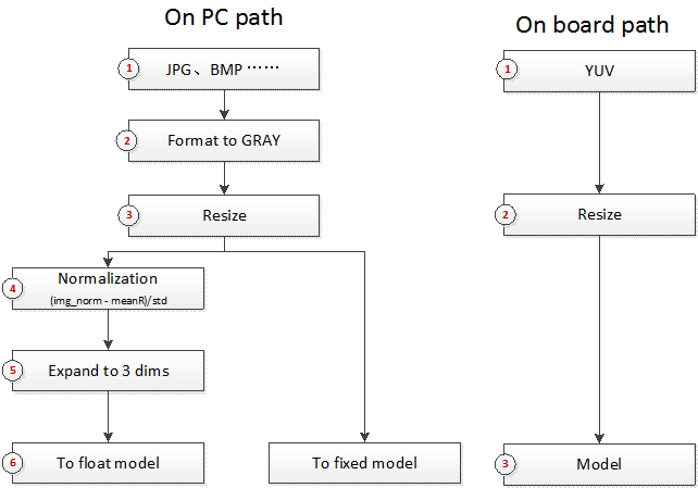
灰度模型,指输入是单通道图片的模型,即输入C维度上为1的模型。
9.1.1. 灰度模型input_config配置信息要点
input_config.ini文件使用在2.2节input config配置信息设置有过介绍,对于灰度模型,要注意如下要点。
input_config.ini文件中这两个配置必须写成
[INPUT_CONFIG]
......
training_input_formats=RGB;
input_formats=GRAY;
......
将灰度图片的有效数据只放在R通道上,因此仅需设置R通道的mean值(mean_red)
[INPUT_CONFIG]
......
mean_red=127.5;
mean_green=0.0;
mean_blue=0.0;
;std_value parameter for image models,
std_value=1.0;
9.1.2. 灰度图片输入模型前处理方法
灰度图片输入的前处理方法与3.2节图片前处理方法要求相同,函数必须包含2个参数:
-
图片路径
-
归一化标记(norm=True)
参考代码SGS_IPU_SDK/Scripts/calibrator/preprocess_method/caffe_lenet.py
import cv2
import numpy as np
def get_image(img_path, resizeH=28, resizeW=28, norm=True, meanR=33.318, std=1):
    img = cv2.imread(img_path, flags=-1)
    try:
        img_dim = img.shape[2]
    except IndexError:
        img_dim = 1
    if img_dim == 3:
        img = cv2.cvtColor(img, cv2.COLOR_BGR2GRAY)
    elif img_dim == 4:
        img = cv2.cvtColor(img, cv2.COLOR_BGRA2GRAY)
    img_norm = cv2.resize(img, (resizeW, resizeH), interpolation=cv2.INTER_LINEAR)
    if norm:
        img_norm = (img_norm - meanR) / std
        img_norm = np.expand_dims(img_norm, axis=2)
        dummy = np.zeros((28, 28, 2))
        img_norm = np.concatenate((img_norm, dummy), axis=2)
        img_norm = img_norm.astype('float32')
    return img_norm
def image_preprocess(img_path, norm=True):
    return get_image(img_path, norm=norm)
Please Note:
- 灰度图片输入模型在PC 上运行与开发板上运行不同。在PC 上需要将单通道图片扩维至3 通道,并在后两个通道 补0。在开发板上需要YUV 图片输入数据。
9.2. RAWDATA_F32_NHWC与RAWDATA_S16_NHWC输入的模型
RAWDATA_F32_NHWC与RAWDATA_S16_NHWC可以用于分段网络的后端网络模型输入,或者非图片数据输入的网络模型。
9.2.1.1 RAWDATA_F32_NHWC模型转换
转换方式与前述介绍基本相同,但配置 input_config.ini 中的
input_formats和training_input_formats都填写RAWDATA_F32_NHWC,quantizations配置为TRUE。
当input_config.ini中的input_formats填写RAWDATA_F32_NHWC时,此时input_config.ini中mean_red、mean_green、mean_blue和std_value不会再在定点网络模型中生效,所有前处理过程都将在输入模型前完成。mean_red、mean_green、mean_blue和std_value不要填写。
模型在calibrator.py转换时使用浮点数据,因此转换方法与正常网络相同。可以参考第3章Calibrator的使用方法。
9.2.1.2 RAWDATA_F32_NHWC模型运行
浮点模型运行时,使用方法与运行图片输入的模型相同。
使用simulator.py运行定点模型时,前处理方法应与浮点前处理模型保持一致,仍然输入norm=True时的方法,所以RAWDATA_F32_NHWC的网络前处理Python文件编写时norm为True和False的实现都应按照norm为True时编写。
使用calibrator_custom.fixed_simulator时,输入数据类型为float32。
>>> import calibrator_custom
>>> model = calibrator_custom.fixed_simulator('./mobilenet_v2_fixed.sim')
>>> input_details = model.get_input_details()
>>> print(input_details)
[{'shape': array([ 1, 513, 513, 3]), 'name': 'sub_7', 'dtype': <class 'numpy.float32'>, 'index': 0}]
已使用float网络的前处理处理完图片,返回numpy.ndarray格式的变量img
>>> print(img.shape)
(1, 513, 513, 3)
>>> print(img.dtype)
float32
>>> model.set_input(input_details[0]['index'], img)
在板上运行RAWDATA_F32_NHWC的网络时,可以参考如下代码,FillInputData函数的输入分别是浮点输入数据的数组,MI_IPU输入Tensor结构体和MI_IPU网络描述结构体。
void FillInputData(MI_FLOAT* pfData, MI_IPU_TensorVector_t& InputTensorVector, MI_IPU_SubNet_InputOutputDesc_t& desc)
{
    const MI_U32 H = desc.astMI_InputTensorDescs[0].u32TensorShape[1];
    const MI_U32 W = desc.astMI_InputTensorDescs[0].u32TensorShape[2];
    const MI_U32 C = desc.astMI_InputTensorDescs[0].u32TensorShape[3];
    MI_FLOAT* pTensorData = (MI_FLOAT*)InputTensorVector.astArrayTensors[0].ptTensorData[0];
    if (desc.eElmFormat == MI_IPU_FORMAT_FP32)
    {
        memcpy(pTensorData, pfData, H * W * C * sizeof(MI_FLOAT));
    }
}
注意事项
只有使用RAWDATA_F32_NHWC配置的网络在板上memcpy完数据后不要调用MI_SYS_FlushInvCache。
9.2.2.1 RAWDATA_S16_NHWC模型转换
使用该种方式输入时,由于硬件的限制条件,所以需要提前排列好数据后才能进行计算。
转换方式与前述介绍基本相同,但配置 input_config.ini 中的training_input_formats
和input_formats时都填写RAWDATA_S16_NHWC。
当input_config.ini中的training_input_formats和input_formats都填写RAWDATA_S16_NHWC时,此时input_config.ini中mean_red、mean_green、mean_blue和std_value不会再在定点网络模型中生效,所有前处理过程都将在输入模型前完成。mean_red、mean_green、mean_blue和std_value不要填写。
由于模型在calibrator.py转换时仍然使用浮点数据,因此转换方法与正常网络相同。可以参考第3章Calibrator的使用方法。
9.2.2.2 RAWDATA_S16_NHWC模型运行
浮点模型运行时,使用方法与运行图片输入的模型相同。
使用simulator.py运行定点模型时,前处理方法应与浮点前处理模型保持一致,仍然输入norm=True时的方法,所以RAWDATA_S16_NHWC的网络前处理Python文件编写时norm为True和False的实现都应按照norm为True时编写。simulator.py会读入原浮点数据,进行反量化和对齐排列后输入给定点模型。
使用calibrator_custom.fixed_simulator时,定点化和对齐排列过程需要自行完成。以下为例,说明定点化和对齐排列过程的做法。
>>> import calibrator_custom
>>> model = calibrator_custom.fixed_simulator('./mobilenet_v2_s16_fixed.sim')
>>> input_details = model.get_input_details()
>>> print(input_details)
[{'input_formats': 'RAWDATA_S16_NHWC', 'training_input_formats': 'RAWDATA_S16_NHWC', 'shape': array([ 1, 513, 513, 8]), 'name': 'sub_7', 'dtype': <class 'numpy.int16'>, 'index': 0, 'quantization': (3.0518509447574615e-05, 0)}]
已使用float网络的前处理处理完图片,返回numpy.ndarray格式的变量img
>>> print(img.shape)
(1, 513, 513, 3)
>>> ins, zp = input_details[0]['quantization']
>>> img = (img / ins + zp).astype(input_details[0]['dtype'])
>>> print(img.dtype)
int16
>>> img_s16 = np.zeros(input_details[0]['shape']).astype('int16')
>>> img_s16[:, :, :, :3] = img
>>> model.set_input(input_details[0]['index'], img_s16)
在板上运行RAWDATA_S16_NHWC的网络时,也需要完成输入数据的定点化和对齐排列过程,可以参考如下代码,FillInputData函数的输入分别是浮点输入数据的数组,MI_IPU输入Tensor结构体和MI_IPU网络描述结构体。
#define ALIGN_UP(x, align) (((x) + ((align) - 1)) & ~((align) - 1))
#define CLIP3(x, min, max) ((x) < (min) ? (min) : ((x) > (max) ? (max) : (x)))

void FillInputData(MI_FLOAT* pfData, MI_IPU_TensorVector_t& InputTensorVector, MI_IPU_SubNet_InputOutputDesc_t& desc)
{
const MI_U32 H = desc.astMI_InputTensorDescs[0].u32TensorShape[1];
const MI_U32 W = desc.astMI_InputTensorDescs[0].u32TensorShape[2];
const MI_U32 C = desc.astMI_InputTensorDescs[0].u32TensorShape[3];
const MI_U32 inner_size = ALIGN_UP(C, 8); const MI_U32 outer_size = H * W;
const MI_FLOAT Scale = desc.astMI_InputTensorDescs[0].fScalar;
const MI_S64 ZeroPoint = desc.astMI_InputTensorDescs[0].s64ZeroPoint;
MI_S16* pData = (MI_S16*)InputTensorVector.astArrayTensors[0].ptTensorData[0];
for (MI_U32 i = 0; i < outer_size; i++) {
    for (MI_U32 j = 0; j < C; j++) {
        *(pData + i * inner_size + j) = (MI_S16)CLIP3(round(pfData[i * C + j] / Scale + ZeroPoint), -32768 , 32767);
        }
    }
    MI_SYS_FlushInvCache(pData, inner_size * outer_size * sizeof(MI_S16));
}
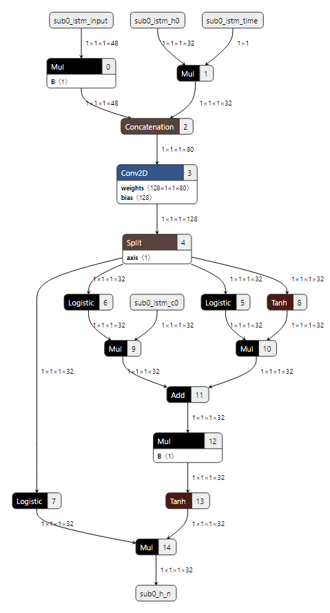
9.3. LSTM模型转换要点
目前仅支持caffe和onnx框架下带有LSTM Layer的网络转换。
本节只对caffe model转换成float.sim的过程说明(onnx model类似),float.sim的后续转换过程上文有描述,这里不再赘述。
转换过程分为3步
-
主网络转换
-
LSTM子网络生成
-
合并主网络和LSTM子网络。
转换过程中会有一些中间文件的生成和读取,建议在同一个目录下执行命令,完成上述3步。
9.3.1主网络转换
与第二节Conver Tool使用方法类似,参考命令如下:
python3 ~/SGS_IPU_SDK/Scripts/ConvertTool/ConvertTool.py caffe \
--model_file ~/SGS_Models/caffe/caffe_lstm/caffe_lstm.prototxt \
--weight_file ~/SGS_Models/caffe/caffe_lstm/caffe_lstm.caffemodel \
--input_arrays data \
--output_arrays prob \
--output_file ./caffe_lstm_float.sim \
--input_config ~/SGS_Models/caffe/caffe_lstm/input_config.ini
9.3.2 LSTM子网络生成
每个LSTM的结构都是相似的,只是其中卷积的权重和运算数据shape的差异。所以我们根据前一步生成的中间文件,生成LSTM子网络。参考命令如下:
python3 ~/SGS_IPU_SDK/Scripts/postprocess/postprocess.py \
-n caffe_lstm_unroll
python3 ~/SGS_IPU_SDK/Scripts/postprocess/postprocess.py \
-n onnx_lstm_unroll
9.3.3 合并主网络和LSTM子网络
编写ini文件。此时ini文件中的inputs和outputs分别为主网络的inputs和outputs 如下为主网络只有一个输入和一个输出的ini文件参考,input_config.ini
[INPUT_CONFIG]
;Names of the input arrays, comma-separated.image input must be the first.
inputs=data;
;Memory formats of input arrays, comma-separated. ;One of RGB, BGR, RGBA, BGRA, YUV_NV12, RAWDATA_S16_NHWC, RAWDATA_S16_NHWX, RAWDATA_U8_NHWC, RAWDATA_U8_NHWX
;Each entry in the list should match an entry in inputs arrays.
training_input_formats=BGR;
;Indicate the input data need qauntize or not.
;Each entry in the list should match an entry in inputs arrays.
quantizations=TRUE;
;mean_values parameter for image models,
;Each entry in the list match RGB channel of(RGB,BGR,RGBA,BGRA,YUV_NV12)
mean_red=0.0;
mean_green=0.0;
mean_blue=0.0;
;std_value parameter for image models,
std_value=1.0;
[OUTPUT_CONFIG]
;Names of the output arrays, comma-separated.
outputs=prob;
;Indicate the output data need deqauntize or not.
;Each entry in the list should match an entry in outputs arrays.
dequantizations=TRUE;
[CONV_CONFIG]
;tensor_arrays='concat_out';
~/SGS_IPU_SDK/bin/concat_net \
--mode concat \
--input_config ~/SGS_Models/caffe/caffe_lstm/input_config.ini \
--model1 ./caffe_lstm_float.sim \
--model2 ./SGS_LSTM_sub0_unroll.sim \
--output ./lstm_float_concat.sim
~/SGS_IPU_SDK/bin/concat_net \
--mode concat \
--input_config ~/SGS_Models/caffe/caffe_lstm/input_config.ini \
--model1 ./lstm_float_concat.sim \
--model2 ./SGS_LSTM_sub1_unroll.sim \
--output ./lstm_float_concat.sim
9.4. 分段网络转换要点
网络中有不支持的Layer,可将完整网络分段执行。前一段网络运行完成后将结果输入给自定义实现层,再将自定义层的输出结果作为第二段网络的输入运行。下面以Faster_RCNN网络为例,说明如何转换分段网络。
9.4.1 网络切分
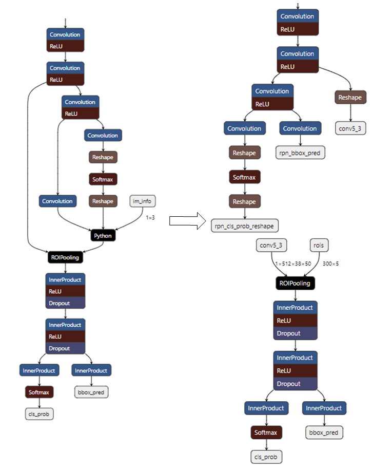
Faster_RCNN网络中的Proposal Layer是不支持的,我们需要将网络从该层分成两段。
如下图所示,图中的Python Layer是Proposal Layer,通过修改prototxt文件,将网络从Proposal Layer处拆成两段:第一段网络将有3个输出,其中rpn_cls_prob_reshape和rpn_bbox_pred两个输出结果将作为Proposal Layer的输入,conv5_3和Proposal Layer的输出将作为第二段网络的输入。
第一段网络的输入是图片数据,input_config.ini和前处理python文件按照2.2和3.2节处理。第二段网络的输入不是图片数据,可以参考9.2节对两个输入同时采用RAWDATA_S16_NHWC的格式配置。配置完成后,通过
ConvertTool.py分别将两个网络转换成float.sim模型文件。具体配置文件和转换命令如下:
第一段网络:
python3 ~/SGS_IPU_SDK/Scripts/ConvertTool/ConvertTool.py caffe \
--model_file test_stageone.prototxt \
--weight_file VGG16_faster_rcnn_final.caffemodel \
--input_arrays data \
--output_arrays rpn_cls_prob_reshape,rpn_bbox_pred,conv5_3 \
--input_config input_config.ini \
--output_file faster_rcnn_main_float.sim
[INPUT_CONFIG]
inputs=data;
input_formats=BGR;
quantizations=TRUE;
mean_red=122.7717;
mean_green=115.9465;
mean_blue=102.9801;
std_value=1;
[OUTPUT_CONFIG]
outputs=rpn_cls_prob_reshape,rpn_bbox_pred,conv5_3;
dequantizations=TRUE,TRUE,FALSE;
第二段网络:
ROIPooling的rois输入维度为(N×5),当后段网络全部是InnerProduct时,N才可以设置为300(如上图所示),如果后段网络中有卷积时,N仅可以设置为1,第二段网络需要循环执行N次。
python3 ~/SGS_IPU_SDK/Scripts/ConvertTool/ConvertTool.py caffe \
--model_file second_stage.prototxt \
--weight_file VGG16_faster_rcnn_final.caffemodel \
--input_arrays conv5_3,rois \
--output_arrays cls_prob,bbox_pred \
--input_config input_config_stage2.ini \
--output_file faster_rcnn_stage2_float.sim
[INPUT_CONFIG]
inputs=conv5_3,rois
input_formats=RAWDATA_F32_NHWC,RAWDATA_F32_NHWC;
quantizations=TRUE,TRUE;
[OUTPUT_CONFIG]
outputs=cls_prob,bbox_pred;
dequantizations=TRUE,TRUE;
9.4.2 转换网络
工具路径SGS_IPU_SDK/Scripts/examples/caffe_faster_rcnn/faster_rcnn_calibrator.py 该工具作为Faster_RCNN网络转换demo,直接运行即可将两段网络直接转换成fixed模型。
python3 ~/SGS_IPU_SDK/Scripts/examples/caffe_faster_rcnn/faster_rcnn_calibrator.py \
-i ~/SGS_Models/resource/detection/voc_calibration_set32/ \
-m0 faster_rcnn_main_float.sim \
-m1 faster_rcnn_stage2_float.sim \
--input_config0 input_config.ini \
--input_config1 input_config_stage2.ini
在转换分段网络时,首先定义网络的两段网络,再组织两段网络的运行方式,定义在forward方法里:
class Net(calibrator_custom.SIM_Calibrator):
    def __init__(self, main_model_path, main_input_config, second_model_path, second_input_config):
        super().__init__()
        self.main_model = calibrator_custom.calibrator(main_model_path, main_input_config)
        self.second_model = calibrator_custom.calibrator(second_model_path, second_input_config)
        self.rpn = rpn.ProposalLayer()
    def forward(self, x):
        out_details = self.main_model.get_output_details()
        input_data, im_scale = fill_inputImg2main(x)
        self.main_model.set_input(0, input_data)
        self.main_model.invoke()
        result_list = []
        for idx, _ in enumerate(out_details):
            result = self.main_model.get_output(idx)
            result_list.append(result)
        im_info = np.array([x.shape[0], x.shape[1], im_scale]).reshape(1, 3)
        bottom = [result_list[0], result_list[1], im_info]
        roi = self.rpn.forward(bottom)
        out2_details = self.second_model.get_output_details()
        self.second_model.set_input(0, result_list[2])
        self.second_model.set_input(1, roi)
        self.second_model.invoke()
        second_result = []
        for idx, _ in enumerate(out2_details):
            result = self.second_model.get_output(idx)
            second_result.append(result)
        return second_result
net = Net()
net.convert(img_gen, num_process=num_subsets, fix_model=[out_main_model, out_second_model])
9.4.3 运行网络
工具路径SGS_IPU_SDK/Scripts/examples/caffe_faster_rcnn/faster_rcnn_simulator.py 该工具作为Faster_RCNN网络运行demo,直接运行两段网络。
python3 ~/SGS_IPU_SDK/Scripts/examples/caffe_faster_rcnn/faster_rcnn_simulator.py \
-i ~/SGS_Models/resource/detection/004545.jpg \
-m0 faster_rcnn_main_float.sim \
-m1 faster_rcnn_stage2_float.sim \
-t Float
运行两段模型的方法与转换网络时类似,需要注意的是Fixed模型和Offline的第二段模型的roi输入时需要先将数据乘0.0625。
class Net(calibrator_custom.SIM_Simulator):
    def __init__(self, main_model_path, second_model_path, phase):
        super().__init__()
        if phase == 'Float':
            self.main_model = calibrator_custom.float_simulator(main_model_path)
            self.second_model = calibrator_custom.float_simulator(second_model_path)
            self.norm = True
        elif phase == 'Fixed':
            self.main_model = calibrator_custom.fixed_simulator(main_model_path)
            self.second_model = calibrator_custom.fixed_simulator(second_model_path)
            self.norm = False
        else:
            self.main_model = calibrator_custom.offline_simulator(main_model_path)
            self.second_model = calibrator_custom.offline_simulator(second_model_path)
            self.norm = False
        self.rpn = rpn.ProposalLayer()
    def forward(self, x):
        # Run main model
        out_details = self.main_model.get_output_details()
        input_data, im_scale = fill_inputImg2main(x, norm=norm)
        self.main_model.set_input(0, input_data)
        self.main_model.invoke()
        def forward(self, x):
            out_details = self.main_model.get_output_details()
            input_data, im_scale = fill_inputImg2main(x)
            self.main_model.set_input(0, input_data)
            self.main_model.invoke()
            result_list = []
            for idx, _ in enumerate(out_details):
                result = self.main_model.get_output(idx)
                result_list.append(result)
            im_info = np.array([x.shape[0], x.shape[1], im_scale]).reshape(1, 3)
            bottom = [result_list[0], result_list[1], im_info]
            roi = self.rpn.forward(bottom)
            out2_details = self.second_model.get_output_details()
            self.second_model.set_input(0, result_list[2])
            if self.norm:
                self.second_model.set_input(1, roi)
            else:
                self.second_model.set_input(1, roi * 0.0625)
            self.second_model.invoke()
            second_result = []
            for idx, _ in enumerate(out2_details):
                result = self.second_model.get_output(idx)
                second_result.append(result)
            return second_result
net = Net()
results = net(img_gen, num_process=num_subsets)
9.5. 多输入网络转换要点
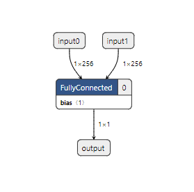
9.5.1 构建多输入网络
使用Tensorflow1.14.0构建一个双输入网络,该网络用来做矩阵乘法,计算两个向量的内积。
import tensorflow as tf
import numpy as np

SHAPE_DIMS = 256

input_np0 = np.random.rand(1, SHAPE_DIMS).astype(np.float32)
input_np1 = np.random.rand(1, SHAPE_DIMS).astype(np.float32)

input_0 = tf.placeholder(dtype=tf.float32, shape=(1, SHAPE_DIMS), name='input0')
input_1 = tf.placeholder(dtype=tf.float32, shape=(1, SHAPE_DIMS), name='input1')
out = tf.matmul(input_0, tf.reshape(input_1, (SHAPE_DIMS, 1)), name='output')

with tf.Session() as sess:
    results = sess.run(out, feed_dict={input_0: input_np0, input_1: input_np1})

    # Convert .pb
    output_graph_def = tf.graph_util.convert_variables_to_constants(
        sess,
        sess.graph_def,
        ['output']
    )
    with tf.gfile.GFile('matmul.pb', 'wb') as f:
        f.write(output_graph_def.SerializeToString())
    print('matmul.pb Saved!')

# convert to .tflite
tflite_model = tf.lite.TFLiteConverter.from_frozen_graph(
    'matmul.pb',
    ['input0', 'input1'],
    ['output']
)
tflite_model = tflite_model.convert()
with open('matmul.tflite', 'wb') as f:
    f.write(tflite_model)
print('matmul.tflite Saved!')
9.5.2 转换多输入网络
下面将matmul.tflte转换成可以在板上运行的模型文件。 matmul.tflite模型不是图片输入,因此配置input_config.ini文件请参考9.2节。 配置input_config.ini脚本
[INPUT_CONFIG]
inputs=input0,input1;
input_formats=RAWDATA_F32_NHWC,RAWDATA_F32_NHWC;
quantization=TRUE,TRUE;

[OUTPUT_CONFIG]
outputs=output;
dequantization=TRUE;
请先在SGS_IPU_SDK⽬录下运⾏以下脚本,输出Library的路径(已经做过该步骤可忽略):
cd ~/SGS_IPU_SDK
source cfg_env.sh
python3 ~/SGS_IPU_SDK/Scripts/ConvertTool/ConvertTool.py tflite \
--model_file /path/to/matmul.tflite \
--input_config /path/to/input_config.ini \
--output_file /path/to/matmul_float.sim
多输入网络的calibrator过程需要使用calibrator_custom模块,详细可以参考3.4节。但与3.4.2节中不同的是输入的生成器需要配置成双输入。将以下示例文件保存为matmul_calibrator.py。
# -*- coding: utf-8 -*-

import calibrator_custom
import os
import sys
import numpy as np
import argparse
from calibrator_custom import utils

class Net(calibrator_custom.SIM_Calibrator):
    def __init__(self, model_path, input_config):
        super().__init__()
        self.model = calibrator_custom.calibrator(model_path, input_config)

    def forward(self, x, y):
        out_details = self.model.get_output_details()
        self.model.set_input(0, x)
        self.model.set_input(1, y)
        self.model.invoke()
        result_list = []
        for idx in range(len(out_details)):
            result = self.model.get_output(idx)
            result_list.append(result)
        return result_list

def arg_parse():
    parser = argparse.ArgumentParser(description='Calibrator Tool')
    parser.add_argument('-m', '--model', type=str, required=True,
                        help='Model path.')
    parser.add_argument('--input_config', type=str, required=True,
                        help='Input config path.')
    parser.add_argument('--quant_level', type=str, default='L5',
                        choices=['L1', 'L2', 'L3', 'L4', 'L5'],
                        help='Indicate Quantilization level. The higher the level,\
                        the slower the speed and the higher the accuracy.')
    parser.add_argument('--num_process', default=10, type=int,
                        help='Amount of processes run at same time.')
    parser.add_argument('-o', '--output', default=None, type=str,
                        help='Output path for fixed model.')

    return parser.parse_args()

def data_gen():
    calibrator_data = np.random.rand(100, 1, 256).astype(np.float32)
    bench_data = np.random.rand(100, 1, 256).astype(np.float32)
    for i, j in zip(calibrator_data, bench_data):
        yield [i, j]

def main():
    args = arg_parse()
    model_path = args.model
    input_config = args.input_config
    quant_level = args.quant_level
    num_subsets = args.num_process
    output = args.output

    if not os.path.exists(model_path):
        raise FileNotFoundError('No such {} model'.format(model_path))

    if not os.path.exists(input_config):
        raise FileNotFoundError('input_config.ini file not found.')

    net = Net(model_path, input_config)
    print(net)

    # random generate data
    # must change real data when using
    img_gen = data_gen()
    print('\033[31m[WARNING] random generate data,\
          must change real data when using!\033[0m',
          file=sys.stderr)

    out_model = utils.get_out_model_name(model_path, output)
    net.convert(img_gen, num_process=num_subsets,
                quant_level=quant_level, fix_model=[out_model])

if __name__ == '__main__':
    main()
使用编写的matmul_calibrator.py转换matmul_float.sim,生成matmul_fixed.sim。
python3 matmul_calibrator.py \
-m /path/to/matmul_float.sim \
--input_config /path/to/input_config.ini
需要注意的是,量化该模型的输入数据一定要换成真实数据,不然统计生成的fixed模型精度会出错。如果单独量化该模型比较困难,比如它是接在某个网络后面运行的,可以参考9.4节,按照多段网络处理,在calibrator_custom.SIM_Calibrator类里定义多个模型,可以直接生成出多个fixed网络。 最后使用compiler.py转换matmul_fixed.sim,生成matmul_fixed.sim_sgsimg.img。
9.5.3 在PC上运行多输入网络
需要注意的是,运行Float的网络时,输入数据的type需要为float32,输入数据的shape与模型输入shape相同。但是由于matmul的Fixed和Offline模型是RAWDATA_S16_NHWC输入,输入数据需要先反量化到int16,然后对齐后才能输入到模型。所以定义calibrator_custom.SIM_Simulator的forward函数时需要注意该模型的特殊性:
class Net(calibrator_custom.SIM_Simulator):
    def __init__(self, model_path, phase):
        super().__init__()
        if phase == 'Float':
            self.model = calibrator_custom.float_simulator(model_path)
        elif phase == 'Fixed':
            self.model = calibrator_custom.fixed_simulator(model_path)
        else:
            self.model = calibrator_custom.offline_simulator(model_path)

    def forward(self, x, y):
        out_details = self.model.get_output_details()
        self.model.set_input(0, x)
        self.model.set_input(1, y)
        self.model.invoke()
        result_list = []
        for idx, _ in enumerate(out_details):
            result = self.model.get_output(idx)
            result_list.append(result)
        return result_list
9.5.4 在板上运行多输入网络
由于matmul_fixed.sim_sgsimg.img网络输入是RAWDATA_F32_NHWC,可以参考9.2.2节中FillInputData函数,与在PC上相同,需要将输入数据处理后再送入模型。 多输入模型只需在FillInputData函数中增加对模型的第二个输入灌入数据:
// input0
I_FLOAT* pData0 = (MI_FLOAT*)InputTensorVector.astArrayTensors[0].ptTensorData[0];
// input1
I_FLOAT* pData1 = (MI_FLOAT*)InputTensorVector.astArrayTensors[1].ptTensorData[0];