系统相关
1. 使用kernel打开IPV6
如需添加IPV6的支持,打开kernel相关配置,同时需要ifconfig工具支持。Ifconfig工具可以通过busybox进行配置。
具体如下:
-
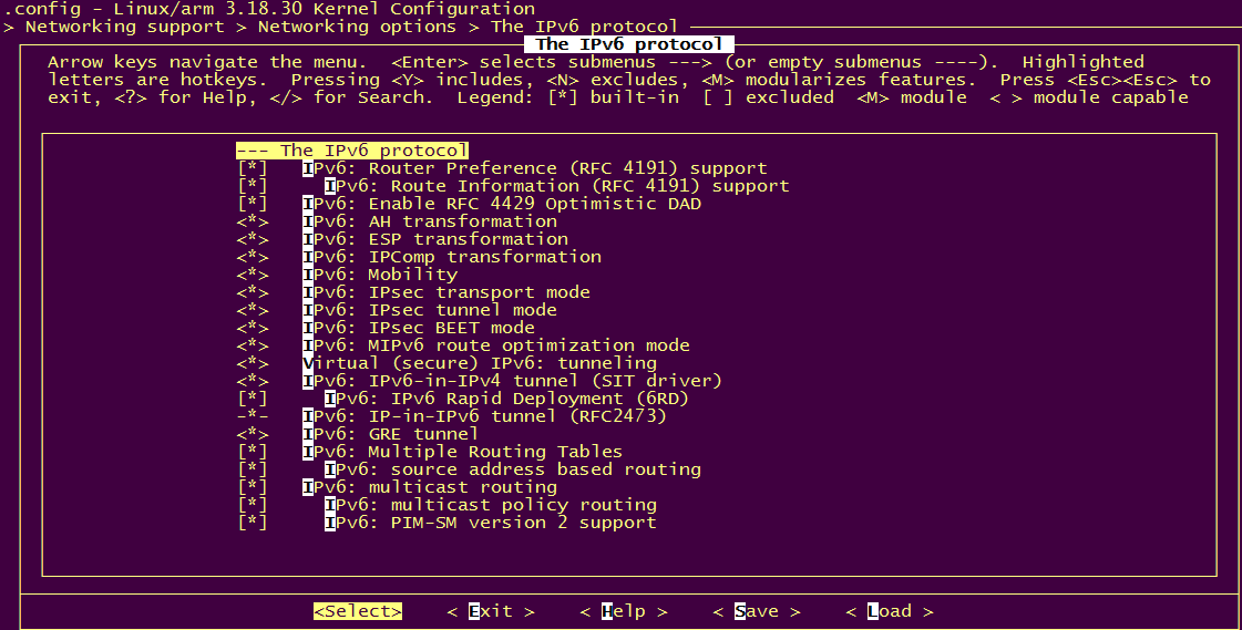
kernel中,打开ipv6的支持,如下:
-
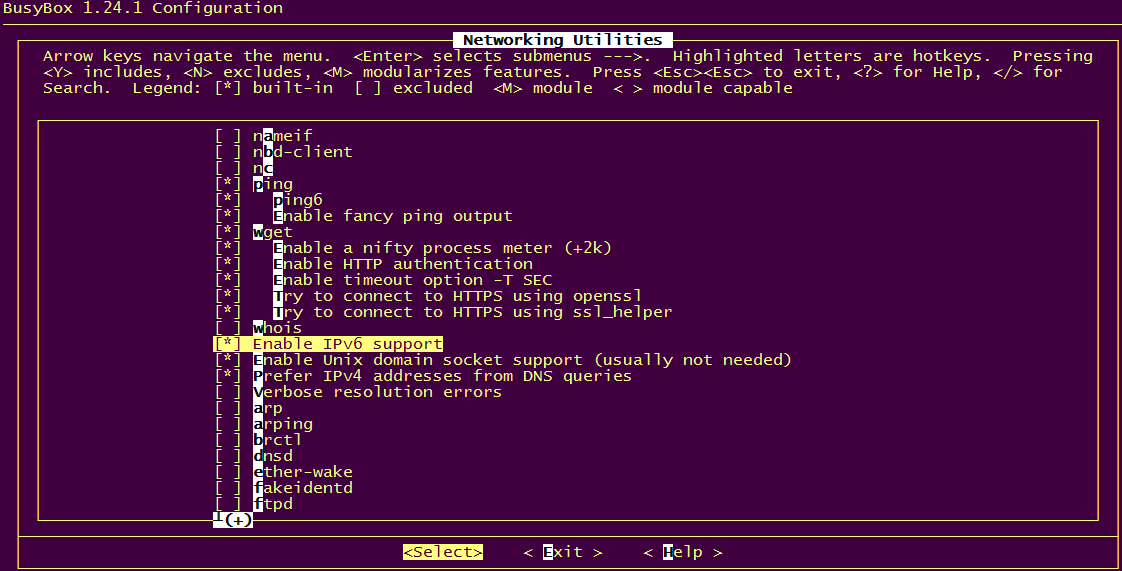
busybox中,打开ipv6的支持,如下:
-
修改rcS脚本,注销nfs驱动安装。
如果安装nfs驱动,则会出现kernel异常,可能是ipv6跟nfs驱动冲突引起,这是因为sdk自带的nfs驱动没有更新引起的。将新编译的nfs相关驱动更新到sdk中,系统可以正常运行。
2. 检测网线插入的sample code
int detect_ethtool(char *ifname)
{
    int skfd;
    if (( skfd = socket( AF_INET, SOCK_DGRAM, 0 ) ) < 0 )
    {
        printf("[ETHTOOL]:socket error\n");
        return 2;
    }
    struct ifreq ifr;
    struct ethtool_value edata;
    memset(&ifr, 0, sizeof(ifr));
    edata.cmd = ETHTOOL_GLINK;
    strncpy(ifr.ifr_name, ifname, sizeof(ifr.ifr_name)-1);
    ifr.ifr_data = (char *) &edata;
    if (ioctl(skfd, SIOCETHTOOL, &ifr) == -1)
    {
        printf("[ETHTOOL]ETHTOOL_GLINK failed: %s\n", strerror(errno));
        close(skfd);
        return 2;
    }
    close(skfd);
    return (edata.data ? 0 : 1);
}
3. neon协处理器代替cpu做memcpy的sample code
#include <stdio.h>

#include <stdlib.h>

#include <unistd.h>

#include <string.h>

#include <sys/time.h>

#include <malloc.h>

static __inline__ void* _aligned_malloc(size_t size, size_t align)
{
    void * malloc_ptr;
    void * aligned_ptr;

    /* Error if align is not a power of two.  */

if(align & (align - 1))
    {
//        errno = EINVAL;
        return ((void*) 0);
    }

    if(size == 0)
        return ((void *) 0);

    /* Assume malloc'd pointer is aligned at least to sizeof (void*).           If necessary, add another sizeof (void*) to store the value         returned by malloc. Effectively this enforces a minimum alignment
        of sizeof double. */
    if(align < 2 * sizeof(void *))
        align = 2 * sizeof(void *);

    malloc_ptr = malloc(size + align);

    if(!malloc_ptr)
        return ((void *) 0);

    /* Align  We have at least sizeof (void *) space below malloc'd ptr. */
    aligned_ptr = (void *)(((size_t) malloc_ptr + align)
                    & ~((size_t)(align) - 1));

    /* Store the original pointer just before p.  */
    ((void **) aligned_ptr) [-1] = malloc_ptr;

    return aligned_ptr;
}

static __inline__ void _aligned_free(void * aligned_ptr)
{
    if(aligned_ptr)
        free(((void **) aligned_ptr) [-1]);
}
void __attribute__ ((noinline)) memcpy_neon_pld(void *dest, const void *src, size_t n)
{
    asm(
    "NEONCopyPLD:\n"
    "   pld [r1, #0xC0]\n" //预取数据
    "   vldm r1!,{d0-d7}\n" //从参数一r0(src)加载8*8=64个单通道8位数据
    "   vstm r0!,{d0-d7}\n" //存储在目的地址r1(dst)中,同样是64个8位单通道8位数据
    "   subs r2,r2,#0x40\n" //循环跳转参数,每次减64,总共循环次数=row*col*4/64
    "   bgt NEONCopyPLD\n"  //以前这里是bge,有问题。现在改成bgt。
    );
}

int main(int argc, char *argv[])
{
    struct timeval begin, end;
    unsigned char *dest, *src;
    unsigned i = 0, index = 0, total = 0, j,s;
    int size[9] = {1024, 2*1024, 4*1024, 8*1024, 16*1024, 128*1024, 512*1024 ,1024*1024, 8*1024*1024};

    if (argc > 1)
        index = atoi(argv[1]);

    for(s = 0; s <= sizeof(size)/sizeof(size[0]); s++)
    {

        printf("size: %dK\n",size[s]/1024);


        dest = (unsigned char*)_aligned_malloc(size[s],0x40);
        if (NULL == dest)
            return 0;

        src = (unsigned char*)_aligned_malloc(size[s],0x40);
        if (NULL == src)
        {
            free(dest);
            return 0;
        }

        memset(src, 0x44, size[s]);
        memset(dest, 0x33, size[s]);


        for (j = 0; j < 32; j++)
        {
            gettimeofday(&begin, NULL);
            if (0 == index)
                memcpy_neon_pld(dest, src, size[s]);
            else
                memcpy(dest, src, size[s]);
            gettimeofday(&end, NULL);


            for (i = 0; i < size[s]; i++)
            {
                if (src[i] != ((dest[i])))
                {
                    printf("error %d src %d dest %d!\n", i, src[i], dest[i]);
//                  break;
                }
            }

            if (i == size[s])
            {
                int tv = 1000000 * (end.tv_sec - begin.tv_sec) + (end.tv_usec - begin.tv_usec);
//              printf("%d. %d us\n", j + 1, tv);
                total += tv;
            }
        }

        printf("average : %u us\n", total / 32);


    }
    _aligned_free(src);
        _aligned_free(dest);
    return 0;
}
4. iperf测试网络吞吐量
-
server:PC client:IPC 走TC PC: iperf.exe -s IPC : iperf -c 192.168.8.100 -t 200 -i 1 (t测试次数,i表示时间间隔)
-
server:IPC client:PC 走TCP PC:iperf.exe -c 192.168.8.117 -t 200 -i 100 IPC:iperf -s
-
server:PC client:IPC 走UDP PC:iperf.exe -s -u (u表示走UDP,默认TCP) IPC:iperf -c 192.168.8.100 -t 200 -i 1 -u (-b 10m/100m指定带宽)
-
server:IPC client:PC 走UDP PC:iperf.exe -c 192.168.8.117 -t 20 -i 1 -u IPC:iperf -s -u
5. isp fifo full异常打印
5.1. ISP FIFO FULL
ISP P0 FIFO FULL(13)(0)

13 input line cnt

0 isp dma line cnt
下一帧数据来了, 但是上一帧还没有做完,发生fifo full。 fifo full发生后,软件会reset isp IP,因为fifo full 一旦发生就会一直回档,通过reset IP,尝试是否可以救回来。
5.2. 常见参数原因
5.2.1. 确认HDR Type 是否正确
im415/SCXXX VC Imx307/274 DoL
5.2.2. VIF->VPE realtime下做了scaling up
在realtime mode下,scl 的处理速度要比Isp更快, scaling up会导致scl处理时间更长,导致isp 比scl 快, 这样scl 就会回档前端。
5.2.3. scl clk 没有设置
cat /sys/class/mstar/mscl/clk
确认scl clk 是否有设置,默认345M ,code在hal_scl.c HalSclHwGetDefaultFclk1Clock
5.3. 底层原因
5.3.1. BW不够
抓取BW 数据
echo 1000 > /sys/devices/system/miu/miu0/monitor_set_duration_ms
//通常取1秒的平均值
echo all > /sys/devices/system/miu/miu0/monitor_client_enable
cat /sys/devices/system/miu/miu0/measure_all
注意:不要在狂刷isp fifo full 打印时去抓BW, isp fifo full打印太多,帧率会下降, 后端IP 的BW一定已经很低,这时候BW没有参考价值。 可以通过尝试降低sensor帧率或者主码流分辨率, 来找到一个临界点FIFO FULL 没有那么多,来抓BW。
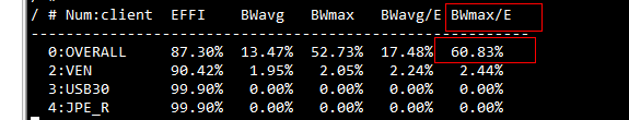
通过all 的Bwmax 峰值判断BW 是否紧张,如果已经到90%,说明已经超规格了。请查看BW数据是否有异常, 是否可以调整IP 访问MIU优先级,降低BW。
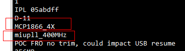
另外可以尝试替换IPL 到更高的clock,可以从1866替换成2133,但要确认所用的DDR是否支持到这个频率。
但是上面提高clk 或者2133 会导致功耗更高。
5.3.2. 后端回档
能够造成回档的两个模块之间一定是realtime。首先要理清楚链路上有哪些realtime模块。通常有 VIF->ISP->SCL->GOP->JPEG, 在发生FIFO FULL时,将一级一级的模块拿掉,判断哪一级回档。
0x1302 0x16 bit0 handshaking ack tie enable
0: isp 吐数据scl
1: isp 断开与scl 连接。
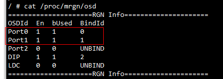
确定scl 上bind 的GOP:
0x121a 0x60 bit0 osd0

0x64 bit0 osd1

0x68 bit0 osd2
关掉对应的Osd hal_scl.c _HalSclDmaSetJpeHandShakeConfig()
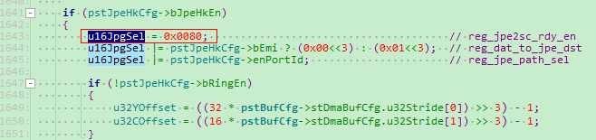
改成0,目前每一张frame 都会写reg,所以riu改没有用(在给mhal提需求提供debug 方法)。
对应reg 0x1218 0x64 bit7,Jpeg to Sc ready control, 设置为0, SC 不看Jpeg 回档。
理清哪个模块造成回档, 然后抓出对应模块reg或者info 提供给我司 debug。
isp/scl debug
scl reg:
/customer/riu_r 1210; /customer/riu_r 1211; /customer/riu_r 1212
/customer/riu_r 1213; /customer/riu_r 1214; /customer/riu_r 1215
/customer/riu_r 1218; /customer/riu_r 1219; /customer/riu_r 121a
/customer/riu_r 1225; /customer/riu_r 122f
cat /sys/class/mstar/mscl/ints
echo vpescl 8 > /sys/class/mstar/mscl/dbgmg
echo halif 6 > /sys/class/mstar/mscl/dbgmg
echo irq 83 > /sys/class/mstar/mscl/dbgmg
cat /proc/kmsg
/customer/riu_r 1302
/customer/riu_r 1304
/customer/riu_r 1308
cat /sys/class/mstar/isp0/isp_info
cat /sys/class/mstar/isp0/isp_ints
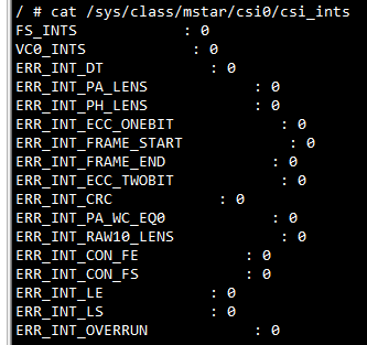
5.3.3. Vsync 不均匀

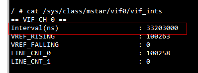
查看interval 时间是否均匀, 不均匀请联系我司进行数据分析。如果Vif这边不均匀还需要看下csi 信号接收是否有ERR_CNT。
5.3.4. Blanking 太短
这里说的Blanking 是指Sc Done 到下一帧Vsync 的时间。
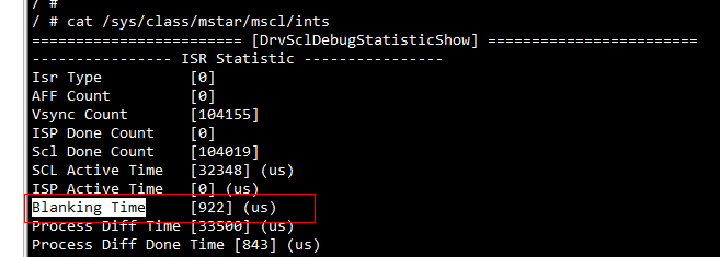
可以通过scl ints 看到对应时间, 一般应该要在500us 以上, 如果太短需要调整sensor 的vts 来调整, 调整关系为:
line_period = HMAX/(INCK*1000000)
frame_interval = line_period * VMAX*1000
INCK: master clock, 通过sensor spec 和 reg 设定得到, 一般通过降低HMAX, 提高VMAX 提高Blanking。
6. 读取芯片温度的方法
#include < fcntl.h >
#include < stdio.h >
#include < ctype.h >
#include < sys/ioctl.h >
#include < sys/types.h >
#include < stdlib.h >
#include < string.h >
#define MSYS_IOCTL_MAGIC 'S'
#define IOCTL_MSYS_READ_PM_TSENSOR _IO(MSYS_IOCTL_MAGIC, 0x78)
int main(int argc, char* argv[])
{
    int fd=-1,ret;
    int temprature=0;
    fd=open("/dev/msys",O_WRONLY);
    if(-1==fd)
    {
        printf("fail to open msys device\n");
        return 0;
    }
    while(1){
        ret = ioctl(fd,IOCTL_MSYS_READ_PM_TSENSOR,&temprature);
        if(ret == 0)printf("temprature = %d\n",temprature);
        else printf("get temprature fail\n");
        sleep(2);
    }
return 0;
}
或者通过命令行:
cat /sys/devices/virtual/mstar/msys/TEMP_R
7. 段错误生成core文件
当应用出现段错误,生成core文件的方法:
-
打开
kernel config:CONFIG_ELF_CORE;CONFIG_COREDUMP(默认已经打开) -
ulimit -c unlimited段错误出现时,产生coredump文件,并且文件大小不限制(或者可以限制足够的size)。
echo "/home/app/core.%e.%p" > /proc/sys/kernel/core_pattern指定段错误时打印core的目录。%e进程名,%p进程号,%tcode dump的时间,%s导致code dump的信号。 -
可以在应用里捕获SIGSEGV信号,然后用backtrace()函数把堆栈信息打印出来。
编译的时候需要加编译选项:
-rdynamic -funwind-tables -ffunction-sections
8. 调整分区表的方法
为了减少flash闲余空间,可以自行调整flash分区表。
SSC3xx系列出厂时带一段ROM code,上电执行顺序为:ROM code -> IPL -> IPL_CUST -> UBOOT->KERNEL。ROM code会从flash 0 Offset地址读取IPL,IPL和IPL_CUST会从40K,48K,60K,128K,256K,512K的位置依次查找分区表信息。UBOOT和KERNEL同理也会去固定位置依次查找分区表:
uboot:位于drivers/mstar/partition/part_mxp.c::static const int mxp_offset[] = {0xA000/40K/, 0xC000/48K/, 0xF000/60K/, 0x20000/128K/, 0x40000/256K/, 0x80000/512K/}; kernel:位于drivers/sstar/flash_isp/part_mxp.c:static const int mxp_offset[] = {0xA000/40K/, 0xC000/48K/, 0xF000/60K/, 0x20000/128K/, 0x40000/256K/, 0x80000/512K/};
调整分区的方法:
-
改mxp_gen.c生成mxp_sf.bin烧录到MXPT分区。
-
如果ENV分区位置调整,需要对应更改uboot代码include/configs/mercury6.h,把宏CONFIG_ENV_OFFSET做对应修改。
-
可以使用IPLX代替IPL+IPL_CUST,能减少一点flash体积。
如果不烧录分区表,使用bootargs传mtdparts的方式:
kernel config一定要打开CONFIG_MTD_CMDLINE_PARTS,CONFIG_MS_FLASH_ISP_MXP_PARTS可以去掉。如果后者没有去掉,实际上mtdparts也会覆盖掉MXP的分区表。
bootars里的 mtdparts 的名字必须是NOR_FLASH。
比如:
bootargs=mtdparts=NOR_FLASH:320K(boot),2048K(kernel),12544K(program),64K(cliinfo),64K(mtd_runtime),1M(config),-(calibration) root=/dev/mtdblock2 rootfstype=squashfs
9. Busybox 下载和编译
说明:公板使用的busybox在project/image/busybox/目录下,make image的时候由脚本解压后打包到文件系统里。也可以自行裁减编译busybox。
9.1. Busybox 下载
开源链接:https://busybox.net/downloads/
如果需要公版使用的config,请联系FAE提供。
9.2. 交叉编译Busybox
-
declare -x ARCH="arm";declare -x
CROSS_COMPILE="arm-linux-gnueabihf-sigmastar-9.1.0-"
-
make menuconfig
根据需要进行裁剪,原则上:
-
不可以裁剪的选项
Busybox Settings -->
Init Utilities -->
Shells -->
Coreutiles --> -
可裁剪的选项
除上述不可裁剪选项外都可以裁剪,另外Coreutiles -> 中看情况裁剪,留下必须的shell命令。
-
-
make clean;make
-
make install
根目录下的
_install是 busybox 安装包 -
release busybox到project目录,然后重新编译project即可
cd _install tar -zcvf _install.tar.gz ./
cp _install.tar.gz /project/image/busybox/
cd ~/project/image/busybox/
mv _install.tar.gz
busybox-1.20.2-arm-linux-gnueabihf-glibc-9.1.0-dynamic.tar.gz
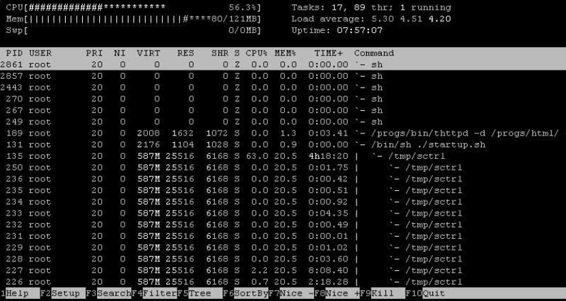
10. htop工具--查看线程占用cpu率
利用 telnet 远程登入目标机,输入如下命令
export TERM=vt102

export TERMINFO=/config/terminfo

/customer/htop
启动 htop 后,按大写 S, 勾选"Display options"->Tree View 和"Show custom thread names", 再按 Esc 返回。就可以查看不同的线程 cpu 占有率情况。
提示,在代码中要显示线程名字,需要调用api pthread_setname_np来进行设置。
而相应的 htop 程序,位于project/release/chip/m6/ipc/common/glibc/9.1.0/bin/debug目录下, terminfo位于project/release/chip/m6/ipc/common/glibc/9.1.0/bin/config_tool。 SDK 默认出来时,会在/config 下面有 terminfo 的配套文件。如果客户的文件系统里没有,可以把terminfo通过mount上去的方式,再改一下export TERMINFO路径即可。
11. 使用riu_r和riu_w读写寄存器
riu_r和riu_w都是16bit width offset。
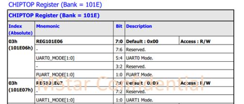
例如写这个寄存器:riu_w 101E 03 FFFF
读这个寄存器:riu_r 101E 03
(需要注意(101E)03才是16bit-width offset,(101E)06/07是8bit-width offset)
内核和uboot对GPIO操作的代码请参考mhal_gpio.c
内核和uboot读写寄存器的代码请参考platform.h
常用的有以下几个:
#define OUTREGMSK8(x, y, z) OUTREG8(x, ((INREG8(x)&~(z))|((y)&(z))))
#define OUTREGMSK16(x, y, z) OUTREG16(x, ((INREG16(x)&~(z))|((y)&(z))))
#define INREG8(x) ms_readb(x)
#define OUTREG8(x, y) ms_writeb((u8)(y), x)
#define INREG16(x) ms_readw(x)
#define OUTREG16(x, y) ms_writew((u16)(y), x)
#define ms_readb(a) (*(volatile unsigned char *)IO_ADDRESS(a))
#define ms_readw(a) (*(volatile unsigned short *)IO_ADDRESS(a))
#define ms_writeb(v,a) (*(volatile unsigned char *)IO_ADDRESS(a) = (v))
#define ms_writew(v,a) (*(volatile unsigned short *)IO_ADDRESS(a) = (v))
以上传的是32位内存地址。可根据规格书转换寄存器的内存地址,方法如下:
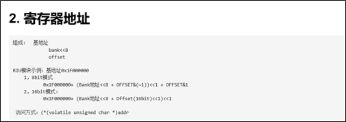
以操作PAD_SAR_GPIO2引脚为例:
-
先从
mhal_gpio.c找到对应的寄存器定义#define GPIO100_PAD PAD_SAR_GPIO2 #define GPIO100_OEN 0x1423, BIT2 #define GPIO100_IN 0x1425, BIT2 #define GPIO100_OUT 0x1424, BIT2
从以上可以看出,output enable对应bank 0x14 地址0x23(8bit)的bit2,写0表示output,写1表示input。
input data 对应bank 0x14地址0x25(8bit)的bit2,output data 对应bank 0x14 地址0x24(8bit)的bit2。
-
从
mhal_gpio.c的MHal_GPIO_Pad_Set()函数里发现,使用PAD_SAR_GPIO2引脚还需要先disable SAR。MHal_SAR_GPIO_WriteRegBit(REG_SAR_MODE,DISABLE,BIT2);—> MHal_SAR_GPIO_REG(REG_SAR_MODE) &= (~BIT2); —>
其中:
#define MHal_SAR_GPIO_REG(addr) (*(volatile U8*)(gSarBaseAddr + (((addr) & ~1)<<1) + (addr & 1)))

#define REG_SAR_MODE       0x22

U32 gSarBaseAddr = 0x1F002800;
可以知道,把bank (0x2800>>8)>>1 ,也就是bank 0x14的0x22(8bit)的bit2写0.
-
综合上述:在Uboot里增加代码把PAD_SAR_GPIO2拉高
OUTREGMSK8( 0x1F000000+( (0x14)<<8+0x22&(~1))<<1 + 0x22&(1) , 0 ,1<<2 );
OUTREGMSK8( 0x1F000000+( (0x14)<<8+0x23&(~1))<<1 + 0x23&(1) , 0 , 1<<2);
OUTREGMSK8( 0x1F000000+( (0x14)<<8+0x25&(~1))<<1 + 0x25&(1) , 0 , 1<<2);
OUTREGMSK8( 0x1F000000+( (0x14)<<8+0x24&(~1))<<1 + 0x24&(1) , 4 ,1<<2 );
把PAD_SPI0_DI拉低或者拉高:
OUTREGMSK8( 0x1F000000+( (0x101E)<<8+0x0F&(~1))<<1 + 0x0F&(1) , 0 ,1<<4 );
OUTREGMSK8( 0x1F000000+( (0x101E)<<8+0x0F&(~1))<<1 + 0x0F&(1) , 0 ,1<<5 );
OUTREGMSK8( 0x1F000000+( (0x103C)<<8+0xE4&(~1))<<1 + 0xE4&(1) , 0 , 1<<5);
OUTREGMSK8( 0x1F000000+( (0x103C)<<8+0xE4&(~1))<<1 + 0xE4&(1) , 1<<4, 1<<4);
把PAD_FUART_RTS拉高:
OUTREGMSK8(0x1F20785C,0<<5,1<<5);
OUTREGMSK8 (0x1F20785C,0<<4,1<<4);
OUTREGMSK8 (0x1F20785C,1<<0,1<<0);//拉高
OUTREGMSK8 (0x1F20785C,0<<0,1<<0);//拉低
12. 读取芯片UUID的方法
例程:
#include <fcntl.h>
#include <stdio.h>
#include <ctype.h>
#include <sys/ioctl.h>
#include <sys/types.h>
#include <stdlib.h>
#include <string.h>
#define MSYS_IOCTL_MAGIC             'S'
#define IOCTL_MSYS_GET_UDID             _IO(MSYS_IOCTL_MAGIC, 0x32)
typedef struct
{
    unsigned int VerChk_Version;
    unsigned long long udid;
    unsigned int VerChk_Size;
} __attribute__((__packed__)) MSYS_UDID_INFO;
int main(int argc, char* argv[])
{
    int sysFd = 0;
    MSYS_UDID_INFO udfo;
    memset(&udfo,0,sizeof(MSYS_UDID_INFO));
    sysFd = open("/dev/msys", O_RDWR);
    if(sysFd<0){
        printf("open /dev/msys fail!\n");
        return 0;
    }
    udfo.VerChk_Version = 0x4d530100;
    udfo.VerChk_Size = sizeof(MSYS_UDID_INFO);
    if(ioctl(sysFd,IOCTL_MSYS_GET_UDID, &udfo)!=0){
        printf("ioctl fail!\n");
    }
    printf("The version is 0x%x, The uuid=%lld, the size=%d\n", udfo.VerChk_Version, udfo.udid, udfo.VerChk_Size);
    close(sysFd);
    return 0;
}
Tiramisu的uuid是烧写在OTP,通过读取bank 101f offset 7c/7d/7e。
riu_r 101f 7c (低16位)
riu_r 101f 7d (中16位)
riu_r 101f 7e  (高16位)
三个16位寄存器值组成48bit UUID。
提供Tiramisu在uboot下读取uuid的代码(比如把以下加在lib/display_iptions.c/dislay_options()):
#include "asm/arch/mach/io.h"
#include "asm/arch/mach/ms_types.h"
#include "asm/arch/mach/platform.h"
unsigned long long udid=0;
udid = (u64)INREG16(0x1F203FF0) | ((u64)(INREG16(0x1F203FF4))<<16) | ((u64)(INREG16(0x1F203FF8)) << 32);
printf(" uuid=%llx\n",udid);
13. Makefile-中echo -e 显示问题
编译SDK生成的image,若根据环境开发搭建用estar命令烧录失败。直接原因是project目录下的Makefile:
echo -e $(foreach n,$(IMAGE_LIST),estar scripts/[[$(n)\\n) >> $(IMAGEDIR)/auto_update.txt
结果在auto_update.txt里把-e也显示出来。
原因:
由于不同的shell(bash和dash)造成的两种不同的结果。
即在bash下正常,在dash下就多显示了一个-e。 从Ubuntu6.10开始,默认使用的shell是dash,dash更快、更高效,可以加快启动速度。
通过查看 ls -l /bin/sh 发现 /bin/sh -> dash。
需要修改ubuntu默认使用bash:sudo dpkg-reconfigure dash
再次查看ls -l /bin.sh 发现/bin/sh -> bash。
14. RNDIS/ECM (网卡)
远程网络驱动接口规范(RemoteNDIS),简称RNDIS,是微软基于ECM定义的USB网络协议。
以太网控制模型(Ethernet Networking Control Model),简称ECM,用于在设备和主机之间传输以太网数据包。
14.1. 板端内核配置(device)
本节将分别介绍在linux 平台以及uboot 使用rndis的配置方法。
14.1.1. linux 平台配置
-> Device Drivers
    -> USB Gadget Support
    -> USB Gadget Drivers
        -> Ethernet Gadget (with CDC Ethernet support)
        -> [*]       RNDIS support
如果选上[*] RNDIS support, 则支持RNDIS虚拟网卡。
生成模块:u_ether.ko usb_f_ecm.ko usb_f_ecm_subset.ko usb_f_rndis.ko g_ether.ko(依赖 libcomposite )
加载顺序:
u_ether.ko
usb_f_ecm.ko
usb_f_ecm_subset.ko
usb_f_rndis.ko
udc-msb250x.ko/dwc3.ko
g_ether.ko
14.1.2. uboot 平台配置
开启配置:
-
CONFIG_CMD_USBSTART
-> Command line interface
    -> USB commands
        [*] usbstart
-
SSTAR_UTMI_POWERON
-> Command line interface
    -> USB commands
        [*] Power on UTMI first
配置环境变量:
setenv usbnet_devaddr 00:30:78:00:00:02
setenv usbnet_hostaddr 00:50:14:00:00:02
setenv ethact usb_ether
setenv ipaddr 10.10.70.3
setenv netmask 255.0.0.0
setenv gatewayip 10.10.70.1
setenv cdc_connect_timeout 20
启动usb device:
usbstart
连上设备可以执行ctrl-c,然后执行ping回到命令行。
14.2. 主机端配置(host)
14.2.1. linux 主机
x CONFIG_USB_NET_RNDIS_HOST:
x
x This option enables hosting "Remote NDIS" USB networking links,
x as encouraged by Microsoft (instead of CDC Ethernet!) for use in
x various devices that may only support this protocol.  A variant
x of this protocol (with even less public documentation) seems to
x be at the root of Microsoft's "ActiveSync" too.
x
x Avoid using this protocol unless you have no better options.
x The protocol specification is incomplete, and is controlled by
x (and for) Microsoft; it isn't an "Open" ecosystem or market.
x
x Symbol: USB_NET_RNDIS_HOST [=m]
x Type  : tristate
x Prompt: Host for RNDIS and ActiveSync devices
x   Location:
x     -> Device Drivers
x       -> Network device support (NETDEVICES [=y])
x         -> USB Network Adapters (USB_NET_DRIVERS [=m])
x           -> Multi-purpose USB Networking Framework (USB_USBNET [=m])
x   Defined at drivers/net/usb/Kconfig:383
x   Depends on: NETDEVICES [=y] && USB_NET_DRIVERS [=m] && USB_USBNET [=m]
x   Selects: USB_NET_CDCETHER [=m]
x   Selected by: USB_NET_RNDIS_WLAN [=n] && NETDEVICES [=y] && WLAN [=n] && USB [=m] && CFG80211 [=m]
相关驱动:cdc-ether.ko usbusbnet.ko rndis_host.ko
14.2.2. window 主机
-
在设备管理器选择需要更新RNDIS驱动的设备
-
右键“更新驱动程序”
-
选择第二项“浏览我的计算机以查找驱动程序软件”
-
选择“从计算机的设备驱动程序选取”
-
选择网络适配器
-
厂商选择:Microsoft, 型号选择远程NDIS 兼容设备
14.3. 网卡使用
-
设备端
网卡名usb0(与linux主机端命名方式一致),配置方式:ifconfig usb0 192.168.1.2
-
主机端
跟正常网卡使用方式一致,需与设备端网卡ip网段保持一致
14.4. 动态分配ip
可以在连接上host的时候自动给host分配ip
配置对象: device
工具需求: udhcpd
创建leases文件:
mkdir /var/lib/misc/ -p

touch /var/lib/misc/udhcpd.leases
创建配置文件:udhcpd.conf
# Sample udhcpd configuration file (/etc/udhcpd.conf)

# The start and end of the IP lease block

start 192.168.1.20 #default: 192.168.0.20
end 192.168.1.254 #default: 192.168.0.254

# The interface that udhcpd will use

interface usb0 #default: eth0

# The maximim number of leases (includes addressesd reserved
# by OFFER's, DECLINE's, and ARP conficts

#max_leases 254 #default: 254
配置网卡ip:
ifconfig usb0 192.168.1.19
执行命令:
udhcpd -fS /customer/udhcpd.conf &