PANEL DEVELOPMENT REFERENCE
1. Overview
It is mainly introduces the usage instructions of the DISP module in the LCD output scene, so that display-related application developers understand the interface and usage process of the display driver, functions and use restrictions of display module. Introduce related debugging and troubleshooting methods.
2. Module Introduction
2.1. Module Function Introduction
-
Support two video layers, layer0 supports 4 windows puzzles, and layer1 uses a single window as PIP.
-
Scaling up of a single window.
-
Cropping of a single window.
-
Support rotate 90/270 with video layer as the unit.
-
video pixel format support NV12.
-
Support PQ adjustment such as Contrast、Hue、Luma、Saturation、Sharpness、Gamma, etc.
-
Support SSC, effectively reduce EMI.
-
Support LCD display (including TTL PANEL, MIPI PANEL), TTL output CLK, support range 9Mhz-75Mhz; MIPI DSI output CLK, support range 100Mbps/lane-1.5Gbps/lane
2.2. Module Source File Introduction
-
alkaid/sdk/interface/inclue/disp/mi_disp.h
Declare that all users of DISP call the API. Define the current version number.
-
alkaid/sdk/interface/inclue/disp/mi_disp_datatype.h
Define the data structure type used by DISP
-
alkaid/sdk/interface/src/disp/disp_api.c
DISP implementation, build and generate libmi_disp.so libmi_disp.a.
3. Module Function
3.1. Multi-picture Stitching
DISP video layer0 hardware has 4 mgwin, the software is abstracted as 4 input ports, which can receive the yuv data(NV12) output by the front-end. The display positions of the 16 input ports can be set arbitrarily on the video layer0, but they cannot be superimposed on each other.
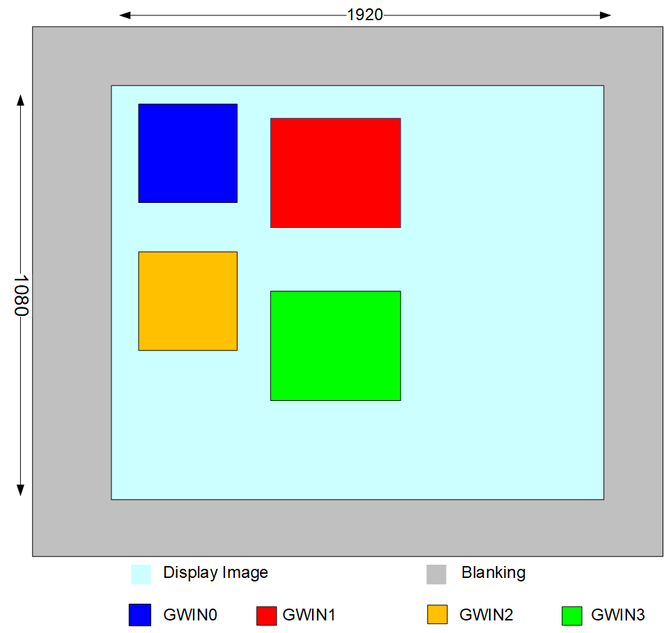
Figure3-1
3.2. PIP
DISP video layer1 can be used for PIP to superimpose the picture on video layer0 to display. The default display priority of video layer1 is higher than video layer0, that is, if they all have content, then video layer1 is on the top and video layer0 is on the bottom.
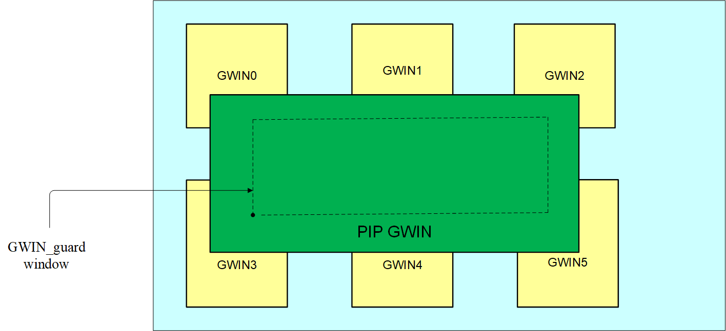
Figure3-2
3.3. Image Scaling
DISP supports scaling up for a single input port, and the H/V direction magnification ratio can reach 16 times to meet the final display size requirements of each window.
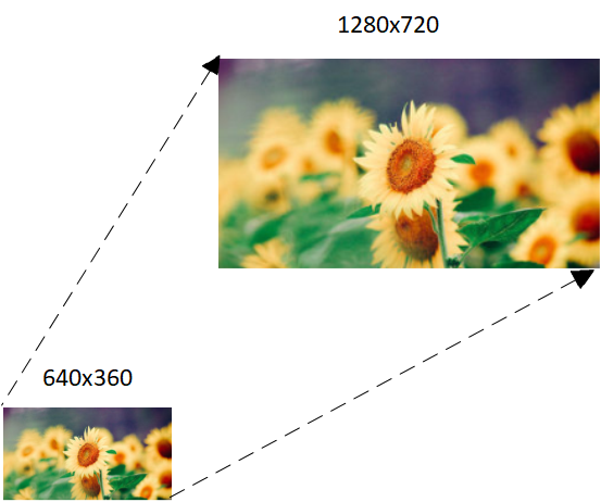
Figure3-3
-
Related APIs:
MI_S32 MI_DISP_SetInputPortAttr(MI_DISP_LAYER DispLayer, MI_DISP_INPUTPORT LayerInputPort, const MI_DISP_InputPortAttr_t *pstInputPortAttr); -
DispLayer
Scaling up an input port on any video layer, the range of the video layer is 0-1.
-
LayerInputPort
Any input port can be used for scaling up. The range of video layer0 is 0-3; Only one port can be used for video layer1.
-
pstInputPortAttr
typedef struct MI_DISP_VidWin_Rect_s
{
¦   MI_U16 u16X;
¦   MI_U16 u16Y;
¦   MI_U16 u16Width;
¦   MI_U16 u16Height;
} MI_DISP_VidWinRect_t;

typedef struct MI_DISP_InputPortAttr_s
{
¦   MI_DISP_VidWinRect_t stDispWin;
¦   MI_U16 u16SrcWidth;
¦   MI_U16 u16SrcHeight;
} MI_DISP_InputPortAttr_t;
Define the attributes of input port
u16SrcWidth:input image width

u16SrcHeight:input image height
u16X: The display position on the layer is offset in the H.
u16Y: The display position on the layer is offset in the V.
u16Width: The width of the image display after scaling up, equal to u16SrcWidth without scaling.
u16Height: The height of the image display after scaling up, equal to u16SrcHeight without scaling.
Same as Multi-picture Stitching, the enlarged windows cannot be superimposed.
The video layer size needs to be equal to the effective width/height of the final output time to be displayed in full screen. For example, Use a panel of 1920x1080 to display, and the effective width of the output time is 1920 and the height is 1080, if only one input port is enabled, and which is required to be displayed in full screen, the following conditions should be satisfied:
u16Width = video layer width

u16Height = video layer height

video layer width = panel active width

video layer height = panel active height
3.4. Image Cropping
DISP supports for cropping input image, it is suitable for scaling up the partial area.
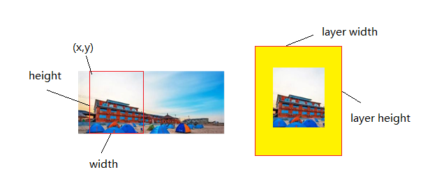
Figure3-4
-
Related APIs:
MI_S32 MI_DISP_SetZoomInWindow(MI_DISP_LAYER DispLayer, MI_DISP_INPUTPORT LayerInputPort, MI_DISP_VidWinRect_t* pstZoomRect); -
DispLayer
Cropping an input port on any video layer, the range of layer id is 0-1.
-
LayerInputPort
Cropping for any input port, the range of video layer0 is 0-3; Only one port can be used for video layer1.
-
pstZoomRect
typedef struct MI_DISP_VidWin_Rect_s
{
¦   MI_U16 u16X;
¦   MI_U16 u16Y;
¦   MI_U16 u16Width;
¦   MI_U16 u16Height;
} MI_DISP_VidWinRect_t;
Set the attributes for cropping:
u16X:crop the start point in H direction

u16Y:crop the start point in V direction

u16Width:crop width

u16Height:crop height
3.5. Image Rotating
DISP supports rotation of 90° or 270° in the unit of layer, and also supports for rotating and scaling up to meet the needs of full screen display after rotation.
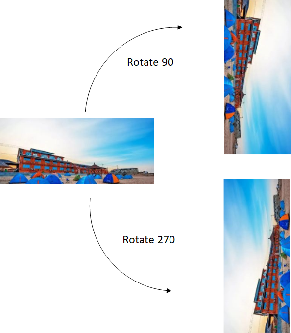
Figure3-5
-
Related APIs:
MI_S32 MI_DISP_SetVideoLayerRotateMode(MI_DISP_LAYER DispLayer, MI_DISP_RotateConfig_t *pstRotateConfig); -
DispLayer
Rotating for any video layer, the range of video layer is 0-1.
-
pstRotateConfig
typedef enum
{
¦   E_MI_DISP_ROTATE_NONE,
¦   E_MI_DISP_ROTATE_90,
¦   E_MI_DISP_ROTATE_180,
¦   E_MI_DISP_ROTATE_270,
¦   E_MI_DISP_ROTATE_NUM,
}MI_DISP_RotateMode_e;
typedef struct MI_DISP_RotateConfig_s
{
¦   MI_DISP_RotateMode_e eRotateMode;
}MI_DISP_RotateConfig_t;
Set the rotation angle, E_MI_DISP_ROTATE_90 rotates 90°, E_MI_DISP_ROTATE_270 rotates 270°, no support for rotating 180°.
3.6. SSC
SSC(short for Spread Spectrum Clocking) disperse the energy concentrated in the narrow frequency range to the set wide frequency range through frequency modulation, to reduce the peak value of the electromagnetic radiation by reducing the amplitude (energy) of the clock at the fundamental frequency and odd harmonic frequencies.

Figure3-6
SSC step/span is calculated by the formula in the Spread Spectrum Calculation Table.
3.7. PQ
3.7.1. xMatrix
DISP supports adjustment of Contrast, Hue, Luma, Saturation, and Sharpness through 3x3 CSC Matrix.
-
Related APIs:
MI_S32 MI_DISP_IMPL_SetLcdParam(MI_DISP_DEV DispDev, MI_DISP_LcdParam_t *pstLcdParam) -
DispDev
Set DISP device ID to 0.
-
pstLcdParam
typedef struct MI_DISP_Csc_s
{
¦   MI_DISP_CscMattrix_e eCscMatrix;    /* eCscMatrix uses the 4th matrix*/
¦   MI_U32 u32Luma;               /* luminance:   0 ~ 100 default: 50 */
¦   MI_U32 u32Contrast;            /* contrast:   0 ~ 100 default: 50 */
¦   MI_U32 u32Hue;              /* hue:   0 ~ 100 default: 50 */
¦   MI_U32 u32Saturation;       /* saturation:  0 ~ 100 default: 40 */
} MI_DISP_Csc_t;

typedef struct MI_DISP_LcdParam_s
{
¦   MI_DISP_Csc_t stCsc;
¦   MI_U32 u32Sharpness;
} MI_DISP_LcdParam_t;
3.7.2. Color Temperature
DISP supports the color temperature adjustment for R/G/B of image.
-
Related APIs:
MI_S32 MI_DISP_DeviceSetColorTempeture(MI_DISP_DEV DispDev, MI_DISP_ColorTemperature_t -
DispDev
Set DISP device ID to 0.
-
pstColorTempInfo
typedef struct
{
¦   MI_U16 u16RedOffset;
¦   MI_U16 u16GreenOffset;
¦   MI_U16 u16BlueOffset;
¦   MI_U16 u16RedColor;  // 00~FF, 0x80 is no change
¦   MI_U16 u16GreenColor;// 00~FF, 0x80 is no change
¦   MI_U16 u16BlueColor; // 00~FF, 0x80 is no change
}MI_DISP_ColorTemperature_t;
3.7.3. Gamma
Method 1: Use SigmaStar System Tool to adjust GAMMA, refer to the following steps:
-
Connect to chip
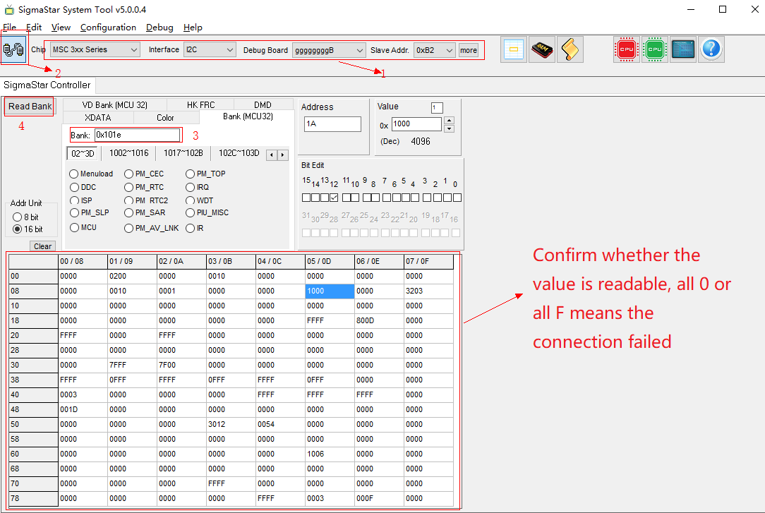
Figure3-7
-
Open the GAMMA adjustment window
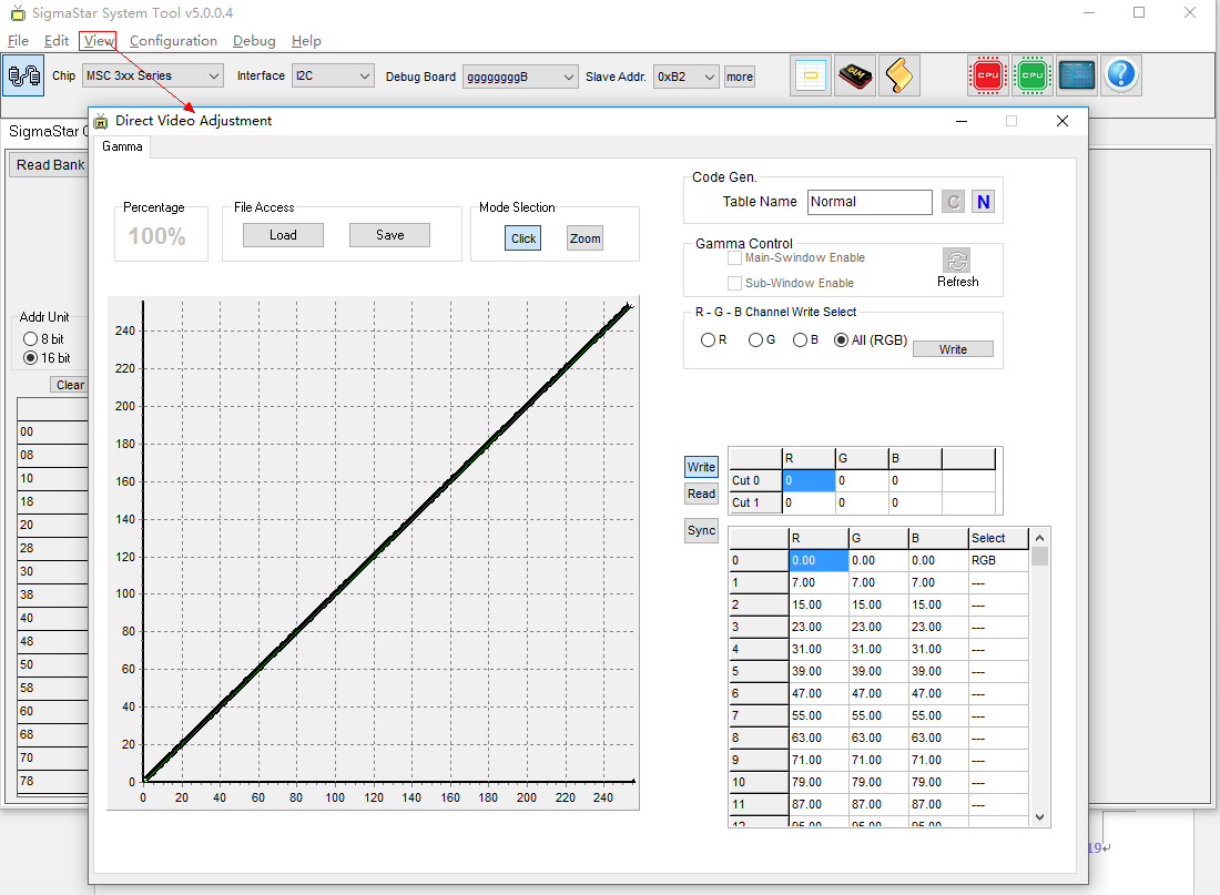
Figure3-8
-
GAMMA adjustment
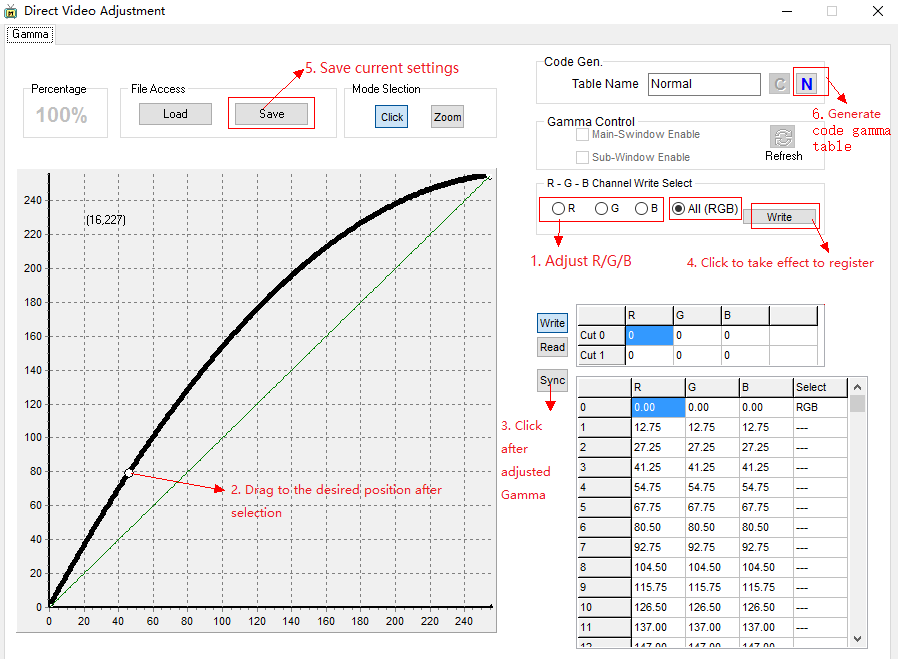
Figure3-9
-
Load gamma settings
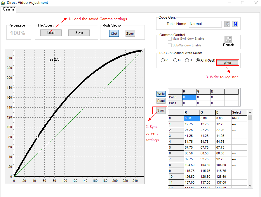
Figure3-10
Method 2: Use DISP to set GAMMA
Use SigmaStar System Tool to generate c code gamma table with the adjusted gamma settings.

Figure3-11
The format of c code gamma table is as follows:
MI_U8 tnormalGammaR[] =
{
¦   0x00,0x07,0x0F,0x17,
¦   0x1F,0x27,0x2F,0x37,
¦   0x3F,0x47,0x4F,0x57,
¦   0x5F,0x67,0x6F,0x77,
¦   0x7F,0x87,0x8F,0x97,
¦   0x9F,0xA7,0xAF,0xB7,
¦   0xBF,0xC7,0xCF,0xD7,
¦   0xDF,0xE7,0xEF,0xF7,
¦   0xFF
};

MI_U8 tnormalGammaG[] =
{
¦   0x00,0x07,0x0F,0x17,
¦   0x1F,0x27,0x2F,0x37,
¦   0x3F,0x47,0x4F,0x57,
¦   0x5F,0x67,0x6F,0x77,
    0x7F,0x87,0x8F,0x97,
¦   0x9F,0xA7,0xAF,0xB7,
¦   0xBF,0xC7,0xCF,0xD7,
¦   0xDF,0xE7,0xEF,0xF7,
¦   0xFF
};

MI_U8 tnormalGammaB[] =
{
¦   0x00,0x07,0x0F,0x17,
¦   0x1F,0x27,0x2F,0x37,
¦   0x3F,0x47,0x4F,0x57,
¦   0x5F,0x67,0x6F,0x77,
¦   0x7F,0x87,0x8F,0x97,
¦   0x9F,0xA7,0xAF,0xB7,
¦   0xBF,0xC7,0xCF,0xD7,
¦   0xDF,0xE7,0xEF,0xF7,
¦   0xFF
};
Call DISP to set GAMMA
MI_DISP_GammaParam_t stGammaParam;
stGammaParam.bEn = TRUE;
stGammaParam.u16EntryNum = sizeof(tnormalGammaR);
stGammaParam.pu8ColorR = tnormalGammaR;
stGammaParam.pu8ColorG = tnormalGammaG;
stGammaParam.pu8ColorB = tnormalGammaB;
MI_DISP_DeviceSetGammaParam(devid, &stGammaParam);
3.8. Output Device
LCD and HDMI/VGA are supported by DISP, which cannot displayed but can output display at the same time. LCD supports TTL PANEL and MIPI PANEL. The section mainly introduces the related operations of lighting TTL or MIPI PANEL.
The DISP data flow is as follows:

Figure3-12
The 4 input ports of DISP video layer0 can be bound to 4 channels of vdec to make 4 windows display together, the port of DISP video layer1 can be used as PIP, that is, video layer1 and layer0 are used as mixers, and the display priority of video layer1 is higher than video layer0.
After the DISP hardware pictures are spliced, according to the output device selected by the user, the video data after the splicing of the pictures is sent out RGB data through the TTL interface according to a certain timing;
The GUI FB/Cursor has an independent HW engine, and the FB device needs to be operated to draw the UI.
3.8.1. TTL
Parallel RGB Interface has DE mode and HV mode, pins VSYNC, HSYNC, DOTCLK, DE and D[0-23] will be used when enable DE, and pins VSYNC, HSYNC, DOTCLK and D[0-23] will be used when enable HV.
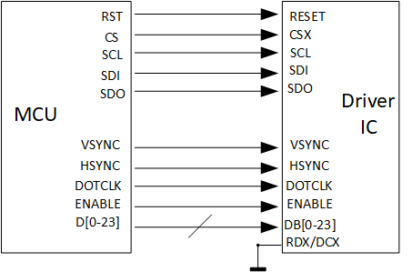
Figure3-13
Some panel driver ICs need to be initialized(Set up the internal register), interfaces SPI and IIC are in charge of communication, the commands and data for initialization are provided by the panel factory, refer panel datasheet for the data format.
Panel using Parallel RGB Interface needs HSYNC, VSYNC, and DOTCLK as synchronization signals. RGB data is only valid in a specific interval of timing.
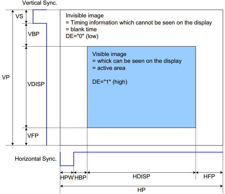
Figure3-14
The blanking interval in the horizontal and vertical scan signals are an invisible, the RGB data in the active interval will be displayed. Different panel Driver IC has different requirements for the blanking interval.
Horizontal scan signal:
Htotal = HSYNC + HBP + HFP + H Active
Vertical scan signal:
Vtotal = VSYNC + VBP + VFP + V Active
Calculate the pixel clock frequency:
Pixel CLK = Htotal * Vtotal * fps
Timing related configuration in panel parameters are used for adjusting HSYNC, HBP, HFP in horizontal scan signal and VSYNC, VBP, VFP in vertical scan signal. The panel spec will provide the length requirements of each part of the blanking interval.
The blanking interval is an adjustable range, and the finally calculated pixel clk is also within a range.
主控芯片一般会有时钟频率的限制,所以在点一个新的panel时,应先计算panel的pixel clk,如果将要点的panel满足像素时钟频率的要求,则一般可以点起来。
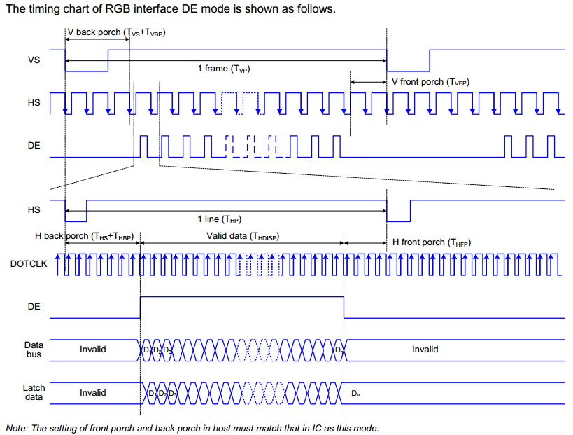
Figure3-15 Parallel RGB Interface Timing
3.8.2. MIPI
MIPI DSI specification:
-
1-4 data lanes, 1 clock lane
-
Level:
-
LP: 0~12V
-
HS: 100~300mV,
-
-
HS: 80Mbps ~ 1.5Gbps/lane
-
Pixel format:
-
16 bpp (5,6,5 RGB) each pixel using two bytes
-
18 bpp (6,6,6 RGB) packed
-
18 bpp (6, 6, 6 RGB) loosely packed into three bytes
-
24 bpp (8, 8, 8 RGB), each pixel using three bytes
-
-
video mode: BURST_MODE/SYNC_EVENT/SYNC_PULSE
-
data/clk chn swap
-
data/clk chn P/N swap
-
data clk skew adjustment
MIPI DPHY timing chart:
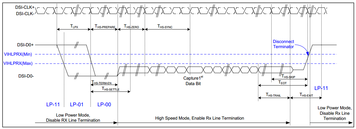
Figure3-16 Data lanes-Low Power Mode to/from High Speed Mode Timing
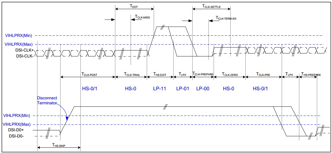
Figure3-17 Clock lanes- High Speed Mode to/from Low Power Mode Timing
Configure HS Timing Parameter:
-
HS_TRAIL/HS_EXIT /HS_PRPR/HS_ZERO/CLK_PRPR/CLK_ZERO/CLK_POST/CLK_TRAIL
Timing specification THS-PREPARE + THS-zero 145ns+10*UI THS-PREPARE 40ns+4*UI ~ 85ns +6*UI THS-ZERO >60ns+4*UI ~105ns+6*UI UI represents the time interval, that is the duration of any HS state on the clock channel.
UI calculation:
H_Total = HACT+HPW+HBP+HFP
V_Total = VACT+VPW+VBP+VFP
BitsPerPixel=24(RGB888)/18(RGB666)/16(RGB565)
Bitrate = (H_Total)*(V_Total)*FPS* BitsPerPixel/lane number
UI = 1/Bitrate

Figure3-18 DSI clock channel timing
Bitrate = 750Mps, UI = 1/Bitrate = 1.333ns, the calculation of HS timing parameter is as follows:
Timing specification Absolute time DA_HS_PREP value(Absolute time/(8*UI)) THS-PREPARE + THS-zero 145ns+10*UI > 158.33 ns > 15 THS-PREPARE 40ns+4*UI ~ 85ns +6*UI 45.32 ~ 92.98 ns 5 ~ 8 THS-zero >60ns+4*UI ~105ns+6*UI > 112.98~ 65.32 ns 10 ~ 7
Configure LP Timing Parameter:
-
CONT_DET/LPX/TA_GET/TA_SURE/TA_GO
low power parameters are recommended to use the default value.
4. Panel Parameter Configuration
4.1. DISP Device Configuration
MI_S32 MI_DISP_SetPubAttr(MI_DISP_DEV DispDev, const MI_DISP_PubAttr_t *pstPubAttr)
-
Configure the attitude of DISP device
Parameter Description DispDev DISP device ID pstPubAttr u32BgColor Background color eIntfType Interface type(点屏使用E_MI_DISP_INTF_LCD) eIntfSync Output timing(点屏使用E_MI_DISP_OUTPUT_USER) stSyncInfo u16Vact Equal to u16Height in panel parameter u16Vbb Equal to u16VSyncBackPorch in panel parameter u16Vfb Equal to u16VTotal-(u16VSyncWidth+u16Height+u16VSyncBackPorch) in panel parameter u16Hact Equal to u16Width in panel parameter u16Hbb Equal to u16HSyncBackPorch in panel parameter u16Hfb Equal to u16HTotal-(u16HSyncWidth+u16Width+u16HSyncBackPorch) in panel parameter u16Hpw Equal to u16HSyncWidth in panel parameter u16Vpw Equal to u16VSyncWidth in panel parameter u32FrameRate Equal to u16DCLK*1000000/(u16HTotal*u16VTotal) in panel parameter Parameters not listed in the table are filled with 0 by default.
MI_S32 MI_DISP_Enable(MI_DISP_DEV DispDev) -
Enable DISP device
Parameter Description DispDev DISP device ID
4.2. DISP Video Layer Configuration
MI_S32 MI_DISP_SetVideoLayerAttr(MI_DISP_LAYER DispLayer, const MI_DISP_VideoLayerAttr_t *pstLayerAttr)
-
Configure the attitude of DISP video layer
Parameter Description DispLayer DISP video layer ID pstLayerAttr stVidLayerDispWin u16X 0 u16Y 0 u16Width Equal to u16Width u16Height Equal to u16Height in panel parameter stVidLayerSize u16Width Equal to u16Width in panel parameter u16Height Equal to u16Height in panel parameter ePixFormat E_MI_SYS_PIXEL_FRAME_YUV_SEMIPLANAR_420 MI_S32 MI_DISP_EnableVideoLayer(MI_DISP_LAYER DispLayer) -
Enable DISP video layer
Parameter Description DispLayer DISP video layer ID
4.3. DISP Input Port Configuration
MI_S32 MI_DISP_SetInputPortAttr(MI_DISP_LAYER DispLayer, MI_DISP_INPUTPORT LayerInputPort, const MI_DISP_InputPortAttr_t *pstInputPortAttr)
-
Configure the attitude of DISP input port
Parameter Description DispLayer DISP video layer ID LayerInputPort DISP input port ID pstInputPortAttr stDispWin u16X Input port display position x offset u16Y Input port display position y offset u16Width Input port display width(It is equal to u16SrcWidth without scaling) u16Height Input port显示height(It is equal to u16SrcHeight without scaling) u16SrcWidth Video source width u16SrcHeight Video source height MI_S32 MI_DISP_EnableInputPort(MI_DISP_LAYER DispLayer, MI_DISP_INPUTPORT LayerInputPort) -
Enable DISP input port
Parameter Description DispLayer DISP video layer ID LayerInputPort DISP input port ID
4.4. Panel Parameter Configuration
MI_S32 MI_PANEL_Init(MI_PANEL_LinkType_e eLinkType)
-
PANEL type setting
Parameter Description eLinkType E_MI_PNL_LINK_TTL E_MI_PNL_LINK_MIPI_DSI MI_S32 MI_PANEL_SetPanelParam(MI_PANEL_ParamConfig_t *pstParamCfg) -
Panel Parameter Setting
Parameter Description pstParamCfg pPanelName Panel type u8Dither 1:enable Dither
0:disable DithereLinkType Interface type
E_MI_PNL_LINK_TTL
E_MI_PNL_LINK_MIPI_DSIu8InvDCLK Pixel clk polarity reversal u8InvDE DE polarity reversal u8InvHSync Hsync polarity reversal u8InvVSync Vsync polarity reversal u16HSyncWidth Horizontal sync signal pulse width u16HSyncBackPorch Horizontal sync signal pulse back porch u16VSyncWidth Vertical sync signal pulse width u16VSyncBackPorch Vertical sync signal pulse back porch u16HStart u16HSyncWidth+16HSyncBackPorch u16VStart u16VSyncWidth+ u16VSyncBackPorch u16Width effective pixels of line u16Height effective lines of field u16HTotal u16HSyncWidth+16HSyncBackPorch+HsyncFrontPorch u16VTotal u16VSyncWidth+ u16VSyncBackPorch+VsyncFrontPorch u16DCLK u16HTotal*u16VTotal*fps u16SpreadSpectrumStep Clock extension amplitude modulation(See Spread spectrum calculation table for details) u16SpreadSpectrumSpan Clock extension frequency modulation(See Spread spectrum calculation table for details) eOutputFormatBitMode Output pixel format u8SwapOdd_RG Swap Channel R
0: default
1: select B
2: select G
3: select Ru8SwapEven_RG Swap Channel G
0:default
1: select B
2: select G
3: select Ru8SwapOdd_GB Swap Channel B
0: default
1: select B
2: select G
3: select Ru8SwapEven_GB Swap Rgb MSB/LSB
0: disable M/L swap
1: enable M/L swapeCh0 Chn0 lane selection(default:2)
0: select lane0
1: select lane1
2: select lane2
3: select lane3
4: select lane4
Selected lane as output of clk laneeCh1 Chn1 lane selection(default: 4)
0: select lane0
1: select lane1
2: select lane2
3: select lane3
4: select lane4eCh2 Chn2 lane selection(default: 3)
0: select lane0
1: select lane1
2: select lane2
3: select lane3
4: select lane4eCh3 Chn3 lane selection(default: 1)
0: select lane0
1: select lane1
2: select lane2
3: select lane3v4: select lane4eCh4 Chn4 lane selection(default: 0)
0: select lane0
1: select lane1
2: select lane2
3: select lane3
4: select lane4Parameters not listed in the table are filled with 0 by default.
MIPI panel needs to configure MIPI DSI, TTL panel only needs to configure panel parameters.
MI_S32 MI_PANEL_SetMipiDsiConfig(MI_PANEL_MipiDsiConfig_t *pstMipiDsiCfg)Parameter Description pstMipiDsiCfg u8HsTrail Default: 0x05
60+4UI ~ MAXu8HsPrpr Default: 0x05
40+4UI ~ 85+6UIu8HsZero Default: 0x05
105+6UI ~ MAXu8ClkHsPrpr Default: 0x05
38ns ~ 95nsu8ClkHsExit Default: 0x05
100ns ~ maxu8ClkTrail Default: 0x05
60ns ~ maxu8ClkZero Default: 0x05
300ns-CLK_HS_PRPRu8ClkHsPost Default: 0x05
60+52UI ~ maxu8DaHsExit Default: 0x05
100ns ~ maxu8ContDet Default:0 u8Lpx Default:16 u8TaGet Default:26
5LPXu8TaSure Default:24
1LPX ~ 2LPXu8TaGo Default:50
4LPXu16Hactive Follow 屏参设定 u16Hpw u16Hbp u16Hfp u16Vactive u16Vpw u16Vbp u16Vfp u16Bllp 0 u16Fps Default:60 enLaneNum E_MI_PNL_MIPI_DSI_LANE_1
E_MI_PNL_MIPI_DSI_LANE_2
E_MI_PNL_MIPI_DSI_LANE_3
E_MI_PNL_MIPI_DSI_LANE_4enformat E_MI_PNL_MIPI_DSI_RGB565
E_MI_PNL_MIPI_DSI_RGB666
E_MI_PNL_MIPI_DSI_LOOSELY_RGB666
E_MI_PNL_MIPI_DSI_RGB888enCtrl E_MI_PNL_MIPI_DSI_CMD_MODE
E_MI_PNL_MIPI_DSI_SYNC_PULSE
E_MI_PNL_MIPI_DSI_SYNC_EVENT
E_MI_PNL_MIPI_DSI_BURST_MODEpu8CmdBuf Mipi panel initializes cmd buff pointer
cmd buff format:
cmd_buff[]=
{
Cmd, parameter cnt, parameter0, parameter1, … ,
Cmd, parameter cnt, parameter0, parameter1, … ,
Cmd, parameter cnt, parameter0, parameter1, … ,
………
}u32CmdBufSize Cmd buff size = sizeof(cmd_buff) u16DataClkSkew Date/clk phase
Range: 7-15u8PolCh0 Chn0 polarity
0:default
1:positive
2:negativeu8PolCh1 Chn1 polarity
0:default
1:positive
2:negativeu8PolCh2 Chn2 polarity
0:default
1:positive
2:negativeu8PolCh3 Chn3 polarity
0:default
1:positive
2:negativeu8PolCh4 Chn4 polarity
0:default
1:positive
2:negative
4.5. PANEL Initialization
Some panels need command to initialize panel diver. The initial command of MIPI panel is transmitted by MIPI data lane0, refer the previous section to fill the cmd buff; TTL panel sends cmd/parameters to the panel driver through SPI, and see the panel datesheet for the required cmd of initialization, issue the corresponding cmd according to the initialization sequence.
If it is a panel initialized by SPI, there is an API for SPI to send data in the SDK.
MI_S32 MI_PANEL_GPIO_Init(MI_PANEL_GpioConfig_t *pstGpioCfg)
Initialize panel reset, panel backlit, panel enable, and pins used by SPI.
| Parameter | Description | |
|---|---|---|
| pstGpioCfg | u16GpioBL | Panel backlit |
| u16GpioRST | Panel reset | |
| u16GpioSCL | SPI | |
| u16GpioSDO | ||
| u16GpioCS | ||
| u16GpioEN | Panel enable | |
MI_S32 MI_PANEL_SetGpioStatus(MI_U16 u16GpioNum, MI_BOOL bValue)
-
Pull up/down a GPIO
Parameter Description u16GpioNum Gpio software num bValue 0:low
1:highMI_S32 MI_PANEL_SetCmd(MI_U32 u32Value, MI_U8 u8Bits) -
send data by SPI
Parameter Description u32Value Data to be sent u8Bits The length of the data (unit: bit)
4.6. Video Display
Complete DISP/PANEL initialization, send the video data that needs to be displayed to DISP, one is to send YUV data directly to DISP, and the other is to bind DISP to a module that can output YUV data, the premise is that the module has been initialized and has data output.
Related APIs needed for the first method:
MI_S32 MI_SYS_ChnInputPortGetBuf (MI_SYS_ChnPort_t *pstChnPort,MI_SYS_BufConf_t *pstBufConf, MI_SYS_BufInfo_t *pstBufInfo, MI_SYS_BUF_HANDLE *pBufHandle, MI_S32 s32TimeOutMs)
MI_S32 MI_SYS_ChnInputPortPutBuf (MI_SYS_BUF_HANDLE bufHandle,  MI_SYS_BufInfo_t *pstBufInfo, MI_BOOL bDropBuf)
Related APIs needed for the second method:
MI_S32 MI_SYS_BindChnPort(MI_SYS_ChnPort_t *pstSrcChnPort, MI_SYS_ChnPort_t *pstDstChnPort,MI_U32 u32SrcFrmrate, MI_U32 u32DstFrmrate)
Refer MI SYS API for details.
5. Reference DEMO
sdk/verify/feature/disp/disp_ut.c
Usage:
-
Build
-
Modify project/release/customer_tailor/nvr_default.mk, add verify_disp:=enable
-
Modify disp_ut.c, include the corresponding panel parameter header file
-
cd sdk/verify/feature;
-
make disp_clean;make disp
-
cp disp/prog to the execution directory
-
-
Run
./prog --interface lcd -l ttl -f ./YUV420SP_800_480.yuv -t yuv420 -n 1 -i 800_480 -c 0_0_800_480 -o 0_0_800_480
--interface //input port, 点屏用lcd
-l //panel type: ttl or mipi
-f //file path
-t //pixel format
-n //chn num
-i //input size
-c //disp crop parameters
-o //disp show size
6. Debugging and Problem
6.1. Debugging
-
procfs
cat /proc/mi_modules/mi_disp/mi_disp0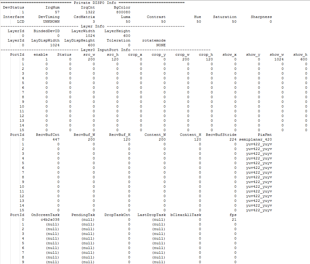
Figure6-1
DISP procfs is mainly used to analyze whether the data flow and the DISP working status are normal, and whether the DISP related settings are correct reasonable.
-
Data flow related:
RecvBufCnt: analyze whether DISP gets the input buff
RecvBuf_W:input buff width
RecvBuf_H:input buff height
Content_W:input buff effective width
Content_H:input buff effective height
RecvBufStride:input buff stride
PixFmt:input buff pixel format
-
Function setting:
crop_x/crop_y/crop_w/crop_h: input port crop parameters
show_x/show_y/show_w/show_h: display input port show size
rotatemode: rotate mode
CscMatrix/Luma/Contrast/Hue/Saturation/Sharpness: PQ
-
Status related:
DevStatus:DISP device enable state
IrqCnt:Number of DISP hardware interrupt times
enable:DISP input port enable state
When DISP displays abnormally, check the above three parts at first.
cat /proc/mi_modules/mi_panel/mi_panel0
Figure6-2
PANEL procfs is mainly used to analyze whether the panel parameter settings are effective.
-
-
register
Registers that need to be concerned about the display:
bank Addr Description 101e 0d [bit8-bit11] TTL mode
0001: SSR201/202
1100: SSR623
[bit12-bit13] MIPI TX mode
01: 4 lane1038 54 [bit0-bit3] clk_mop
[bit0] disable clk
[bit1] inv clk
[bit2-bit3] select clk source
00:320Mhz
01:384Mhz
10:288Mhz
11:clk_miu53 [bit0-bit3] clk_disp_432
[bit0] disable clk
[bit1] inv clk
[bit2-bit3] select clk source
00: 432Mhz
[bit8-bit11] clk_disp_216
[bit8] disable clk
[bit9] inv clk
[bit10-bit11] select clk source
00: 216Mhz
01: 108Mhz63 [bit0-bit5] clk_sc_pixel
[bit0] disable clk
[bit1] inv clk
[bit2-bit5] select clk source
0000:240Mhz
0001:216Mhz
0010:192Mhz
0011:172Mhz
0100:144Mhz
0101:123Mhz
0110:108Mhz
0111:86Mhz
1000:72Mhz
1001:54Mhz
1010:lpll_clk6f [bit0-bit4] clk_mipi_tx_dsi
[bit0] disable clk
[bit1] inv clk
[bit2-bit4] select clk source
000:lpll_clk
001:160Mhz
010:144Mhz
011:108Mhz
100:216Mhz
101:240Mhz1028 07 [bit0-bit3] pattern gen
[bit0] select source of mace
0: from scaling patgen
1: from external video source
[bit1-bit3] select pattern mode
000: 1-pix gray ramp
001: 16-pix gray ramp
010: 32-pix gray ramp
011: 64-pix gray ramp
100: 16-pix gray stick
101: 16-pix colorbar
110: 32-pix colorbar
111: 64-pix colorbar1129 11 [bit0-bit12] h total 12 [bit0-bit12] v total 13 [bit0-bit12] hsync start 14 [bit0-bit12] hsync end 15 [bit0-bit12] vsync start 16 [bit0-bit12] vsync end 17 [bit0-bit12] H frame de start 18 [bit0-bit12] H frame de end 19 [bit0-bit12] V frame de start 1a [bit0-bit12] V frame de end 1b [bit0-bit15] no signal color
[bit0-bit4] B channel
[bit5-bit9] G channel
[bit10-bit14] R channel
[bit15] Forced to show no signal color7e [bit0-bit5] rgb swap
[bit0-bit1] swap for B channel
[bit2-bit3] swap for G channel
[bit4-bit5] swap for R channel
[bit6-bit7] rgb mode
00:rgb 888
01:rgb 666
10:rgb 565-1
11:rgb 565-2
[bit8] MSB/LSB swap1406 00 [bit0] Gwin0 enable 10 [bit0] Gwin1 enable 20 [bit0] Gwin2 enable 30 [bit0] Gwin3 enable 40 [bit0] Gwin4 enable 50 [bit0] Gwin5 enable 60 [bit0] Gwin6 enable 70 [bit0] Gwin7 enable 1407 00 [bit0] Gwin8 enable 10 [bit0] Gwin9 enable 20 [bit0] Gwin10 enable 30 [bit0] Gwin11 enable 40 [bit0] Gwin12 enable 50 [bit0] Gwin13 enable 60 [bit0] Gwin14 enable 70 [bit0] Gwin15 enable 1033 4e [bit0-bit15] ssc
[bit0-bit11] step
[bit15] enable ssc4f [bit0-bit13] ssc span
6.2. Problem
-
The backlight is normal but there is no display.
Please check as follows:
-
Whether the panel parameter meet requirements of panel spec.
-
Whether the data flow is normal, an the buff has input data.
-
Whether the settings of DISP device/layer/input port are correct.
-
Whether the panel init is successful, TTL panel that requires SPI for initialization The TTL panel that needs SPI initialization can measure whether the SPI signal is normal and whether the initial cmd is transmitted correctly.
-
Whether Hsync/Vsync/DE/Dclk polarity meet panel spec.
-
MIPI panel checks whether the clk lane/data lane line sequence is consistent with the software setting.
-
Whether register BK101e addr 0d is switched TTL mode/MIPI mode correctly.
-
Whether the clk related registers are enable.
-
Whether MOP gwin is enable.
-
Whether pattern gen can output normally.
-
-
Split screen
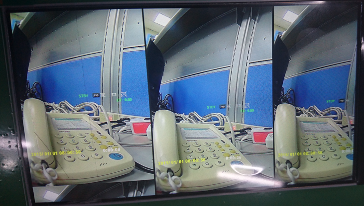
Figure6-3
In the H direction, try to increase Hsync Front porch and Htotal, keep Hsync and Hsync back porch.
In the V direction, try to increase Vsync Front porch and Vtotal, keep Vsync and Vsync back porch.
-
Color cast
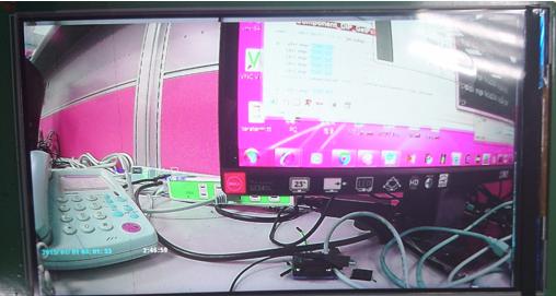
Figure6-4 Color cast
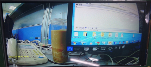
Figure6-5 Normal case
-
Check whether the R/G/B monochrome output is normal. When it is a TTL panel, turn off the 3x3 matrix (BK1129_30 bit0=0, BK1129_3c bit0=0), use BK1129_1b to output RGB monochrome and measure R/ Whether the G/B channel has normal output.
-
Adjust VBP, keep VPW/VFP
-
Check whether R/G/B channel or RGB M/L swap are required.
-
7. TTL/MIPI hardware connection
-
The default hardware connection sequence of chip TTL is as follows:
Pin Number PADName reg_ttl_mode 1 28pin Default Pin56 PAD_TTL0 TTL_DOUT[0] R0 G0 B0 R7/G7/B7 Pin57 PAD_TTL1 TTL_DOUT[1] R1 G1 B1 R6/G6/B6 Pin58 PAD_TTL2 TTL_DOUT[2] R2 G2 B2 R5/G5/B5 Pin59 PAD_TTL3 TTL_DOUT[3] R3 G3 B3 R4/G4/B4 Pin60 PAD_TTL4 TTL_DOUT[4] R4 G4 B4 R3/G3/B3 Pin61 PAD_TTL5 TTL_DOUT[5] R5 G5 B5 R2/G2/B2 Pin65 PAD_TTL6 TTL_DOUT[6] R6 G6 B6 R1/G1/B1 Pin66 PAD_TTL7 TTL_DOUT[7] R7 G7 B7 R0/G0/B0 Pin67 PAD_TTL8 TTL_DOUT[8] G0 B0 R0 Pin68 PAD_TTL9 TTL_DOUT[9] G1 B1 R1 Pin69 PAD_TTL10 TTL_DOUT[10] G2 B2 R2 Pin70 PAD_TTL11 TTL_DOUT[11] G3 B3 R3 Pin71 PAD_TTL12 TTL_DOUT[12] G4 B4 R4 Pin72 PAD_TTL13 TTL_DOUT[13] G5 B5 R5 Pin73 PAD_TTL14 TTL_DOUT[14] G6 B6 R6 Pin74 PAD_TTL15 TTL_DOUT[15] G7 B7 R7 Pin79 PAD_TTL16 TTL_DOUT[16] B0 R0 G0 Pin80 PAD_TTL17 TTL_DOUT[17] B1 R1 G1 Pin81 PAD_TTL18 TTL_DOUT[18] B2 R2 G2 Pin82 PAD_TTL19 TTL_DOUT[19] B3 R3 G3 Pin83 PAD_TTL20 TTL_DOUT[20] B4 R4 G4 Pin84 PAD_TTL21 TTL_DOUT[21] B5 R5 G5 Pin85 PAD_TTL22 TTL_DOUT[22] B6 R6 G6 Pin86 PAD_TTL23 TTL_DOUT[23] B7 R7 G7 Pin87 PAD_TTL24 TTL_CK Pin88 PAD_TTL25 TTL_HSYNC Pin89 PAD_TTL26 TTL_VSYNC Pin90 PAD_TTL27 TTL_DE -
The default hardware connection sequence of chip MIPI is as follows:
Pin Location Ball Pin Name Function Pin65 PAD_TTL6 MIPI_TX_P_CH0 Pin66 PAD_TTL7 MIPI_TX_N_CH0 Pin67 PAD_TTL8 MIPI_TX_P_CH1 Pin68 PAD_TTL9 MIPI_TX_N_CH1 Pin69 PAD_TTL10 MIPI_TX_P_CH2 Pin70 PAD_TTL11 MIPI_TX_N_CH2 Pin71 PAD_TTL12 MIPI_TX_P_CH3 Pin72 PAD_TTL13 MIPI_TX_N_CH3 Pin73 PAD_TTL14 MIPI_TX_P_CH4 Pin74 PAD_TTL15 MIPI_TX_N_CH4