REFERENCE FOR LIGHTING UP PANEL
1. Confirm Whether SPEC Supports
Limited by Takoyaki clk, confirm whether clk is supported before lighting up the panel, the SPEC of Takoyaki clk is as follows:
TTL output CLK, range: 9Mhz-75Mhz.
Calculation: htotal * vtotal * fps
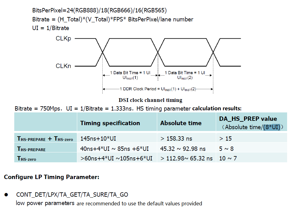
MIPI DSI output CLK, range: 100Mbps/lane – 1.5Gbps/lane
Calculation: H_Total*V_Total*FPS*BitsPerPixel/lane number
BitsPerPixel=24(RGB888)/18(RGB666)/16(RGB565)
2. Pin Configuration
First, confirm the pin used by the hardware(It is best to use the pin listed below, which we had verified.), and then switch to the corresponding mode in the dts of the kernel.
2.1. TTL
Take the public version as an example, PAD_TTL0~PAD_TTL27 is used:

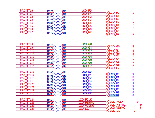
Configure to PINMUX_FOR_TTL_MODE_1 in infinity2m-ssc011a-s01a-padmux-display.dtsi.

2.2. MIPI
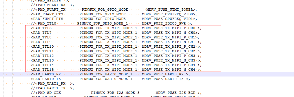
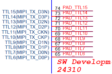
PAD_TTL6~PAD_TTL15 is used as shown below:
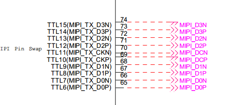
Configure to PINMUX_FOR_TX_MIPI_MODE_1 mode in padmux:
2.3. RMII
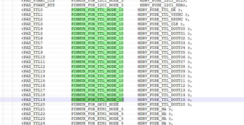
PAD_TTL0~PAD_TTL19 is used as shown below:

Configure to PINMUX_FOR_TTL_MODE_10 in padmux:
3. TTL Panel
Find a configured ttl panel parameter with the same resolution, and then fill in the following parameters according to the panel spec:
u16HSyncWidth & u16HSyncBackPorch & u16VSyncWidth & u16VSyncBackPorch
The data corresponding to panel spec is as follows:
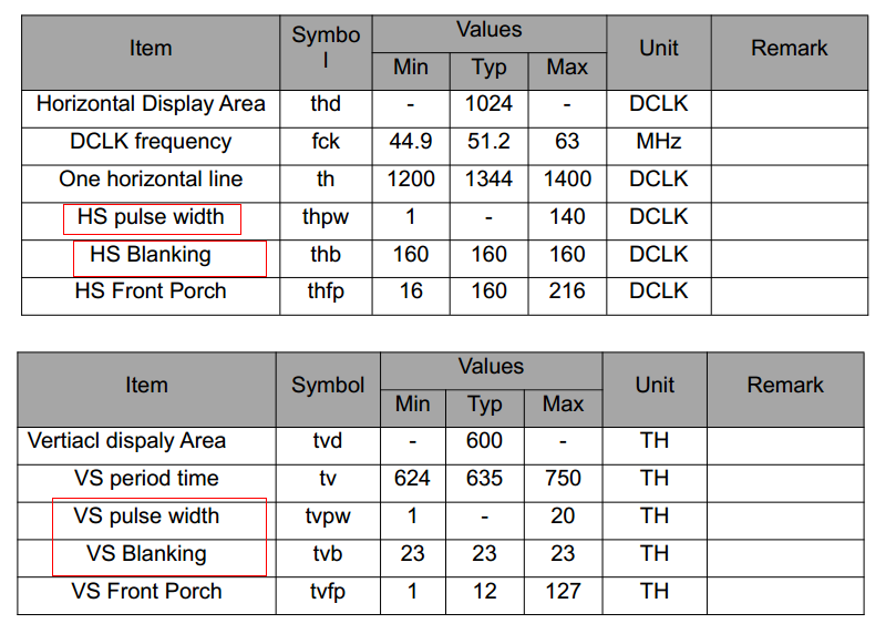
u16HStart = u16HSyncWidth + u16HSyncBackPorch
u16VStart = u16VSyncWidth + u16VSyncBackPorch
u16Width & u16Height corresponded panel spec data is as follows:

u16HTotal = u16Width + u16HSyncWidth + u16HSyncBackPorch + HSyncFrontPorch
u16VTotal = u16Height + u16VSyncWidth + u16VSyncBackPorch + VSyncFrontPorch
The corresponded panel spec data is as follows:
u16DCLK = u16HTotal * u16VTotal * frequence(60)/1000*1000
The following parameters correspond to the data of R G B whether to be swapped.
u8SwapOdd_RG & u8SwapEven_RG & u8SwapOdd_GB
The corresponding channel selection is as follows:
0 default(No swapping)
1 select R
2 select G
3 select B
u8SwapEven_GB indicates whether the high and low bits of the rgb data line need to be swapped
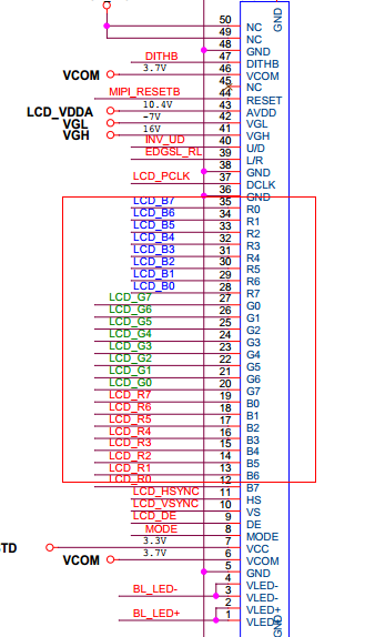
eg: The schematic diagram of the demo board is as follows, R and B and the high and low positions are reversed, so the configuration of the screen parameters is 3,2,1,1.
The corresponding debug registers are as follows:
total - (de end - de start) = bp + fp + sync width

4. MIPI Panel
The panel parameters of MIPI panel and TTL panel are not much different. The main difference is whether additional MIPI data line is required, as follows:
The four pairs of data line & clk line from MIPI whether need to swap are as follows, which can be set according to the line sequence and panel parameter configuration of the public version
The structure members of MI_PANEL_ChannelSwapType_e represent the following groups of pins:
eCh0 → TTL11 - 10
eCh1 → TTL15 - 14
eCh2 → TTL13 - 12
eCh3 → TTL9 - 8
eCh4 → TTL7 - 6
The definition of the corresponding values are as follow:
D0 - 0
D1 - 1
D2 - 3
D3 - 4
CLK - 2
According to the schematic diagram of the public version, the corresponding relationship is as follows:
eg: schematic diagram of demo board and configuration are as follow:

(MI_PANEL_ChannelSwapType_e)2, - clk(TTL11~10)
(MI_PANEL_ChannelSwapType_e)4, - D3(TT15~14)
(MI_PANEL_ChannelSwapType_e)3, - D1(TTL13~12)
(MI_PANEL_ChannelSwapType_e)1, - D2(TTL9~8)
(MI_PANEL_ChannelSwapType_e)0, - D0(TTL7~6)
MI_PANEL_MipiDsiConfig_t focuses on the following parameters:
u16Hactive u16Hpw u16Hbp u16Hfp u16Vactive u16Vpw u16Vbp u16Vfp
The correspondence between parameters and panel spec is as follows:
u16Width u16HSyncWidth u16HSyncBackPorch HSyncFrontPorch
u16Height u16VSyncWidth u16VSyncBackPorch VSyncFrontPorch
The above parameters need to be consistent with MI_PANEL_ParamConfig_t.
enLaneNum corresponds to which line mode of MIPI is according to the actual situation.
pu8CmdBuf u32CmdBufSize corresponds to the initialization cmd of MIPI, the corresponding format is as follows:
-
The MIPI initialization commands provided by the panel company are as follows:
regw(0x01);//Reset
Delay 30ms
regw(0x80,0x58);
regw(0x81,0x47);

regw(0xB0,0x00,0x11,0x18,0x0E,0x11,0x06,0x07,0x08,0x07,0x22,0x04,0x12,0x0F,0xAA,0x31,0x18);
-
The data format to fill in the panel parameters is as follows:
0x01,0,0x0,          //0x01: register, 0:Number of parameters, 0x0: value written to register
FLAG_DELAY, FLAG_DELAY, 30,
0x80,1,0x58,
0x81,1,0x47,

0xB0,
16,0x00,0x11,0x18,0x0E,0x11,0x06,0x07,0x08,0x07,0x22,0x04,0x12,0x0F,0xAA,0x31,0x18,
u8PolCh0 u8PolCh1 u8PolCh2 u8PolCh3 u8PolCh4 corresponding to whether the four group data lines and a clk line need to be reversed.
The following schematic diagram does not need to be reversed.

If clk&data is normal, but the panel is not bright, you can fine-tune BK1033_44[15:7], the default is 9, adjustable range: 6 7 8 9 a b c d e f.
The time difference between clk and data, corresponding to the last one of the mipi panel parameters:
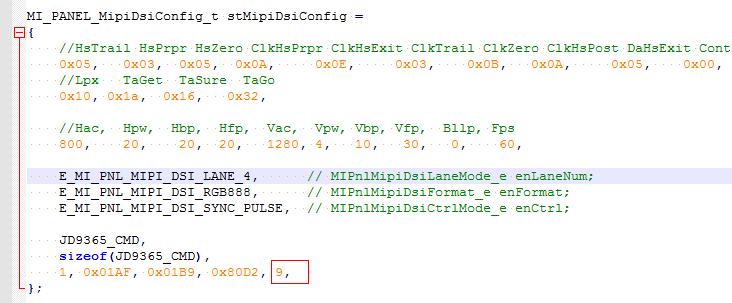
MI_PANEL_MipiDsiConfig_t stMipiDsiConfig =
{
    //HsTrail HsPrpr HsZero ClkHsPrpr ClkHsExit ClkTrail ClkZero ClkHsPost DaHsExit
    ContDet
    0x7, 0x05, 0xC, 0x05, 0x0C, 0x07, 0x1D, 0x0E, 0x0C, 0x00,
    //Lpx TaGet TaSure TaGo
    0x10, 0x1A, 0x18, 0x32,

    //Hac, Hpw, Hbp, Hfp, Vac, Vpw, Vbp, Vfp, Bllp, Fps
1920, 44, 148, 88, 1080, 5, 36, 4, 0, 60,

……
HsTrail HsPrpr HsZero ClkHsPrpr ClkHsExit ClkTrail ClkZero ClkHsPost DaHsExit calculation can refer to MIPI parameter calculation table, fill in H_Total, V_Total, FPS, BitsPerPixel, lane number to automatically calculate the relevant data, round up the number by yourself.
5. Panel Parameter Import
Replace the filled TTL & MIPI panel parameters with the corresponding demo prepared for panel lighting up(H264Player & JpegPlayer), and then run the demo on the board to light up the panel.
6. SPI Panel
-
Open SPI diver by enabling the following two configs in kernel:
CONFIG_SPI_SPIDEV=y
CONFIG_MS_SPI_INFINITY=y
-
Use dts to configure spi related pins, kernel\arch\arm\boot\dts\infinity2m.dtsi
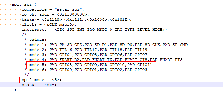
Note: The pins used by spi cannot be configured for other purposes in padmux.
-
Modify makefile, and build the demo of spi to light up the panel.
a. sdk\verify\feature\disp\config.mk

b. project\release\customer_tailor\nvr_i2m_display_glibc_tailor.mk
-
Build the demo of spi to light up the panel.
a. cd sdk/verify/feature
b. make clean;make disp
The compiled demo is in sdk/verify/feature/disp/prog.
-
Put prog and 240_320_rgb565_20.bin in the same directory, execute ./prog to light up the panel

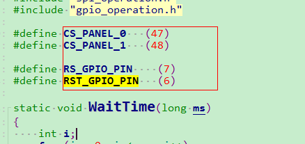
The current demo pin configuration is as follows:
CS GPIO47
CS1 GPIO48
RST GPIO6
RS GPIO7SPI related pins:
CZ GPIO8
CLK GPIO9
DI GPIO10
DO GPIO11If there is a difference with the demo pin, change the pin configuration in the following places in sdk\verify\feature\disp\spi_panel.c
7. FAQ
-
Disable panel clk
/config/riu_w 0x1038 53 101
/config/riu_w 0x1038 63 1
-
Panel list that has been lighted
TTL PANEL
Resolution Pixel CLK(MHz) Model Driver IC 1024x600 51 ADT07016BR50 FITI 480x854 40 LX50FWB4001 ICN9700 800x480 29 SAT050AT40H12B2 1024x600 51 SAT070CP50 480x854 27 TXW500066S0 ST7701S 480x272 9 VS043ISN26V10 ST7282 480x800 28 FRD400H40003 ST7701S-G5 MIPI PANEL
Resolution Pixel CLKMHz LaneNum BitsPerPixel CLK LANEMHz DATA LANEMbps Model Driver IC 800x480 30 4 24 90 180 HONTRON 800x1280 68 4 24 204 408 SAT101CP40I28R1 720x1280 79 4 24 237 474 LX50HDI4002 RM68200 1024x600 52 4 24 156 312 SAT070BO30I21Y0 800x1280 68 4 24 204 408 SAT101AT40I28R1 JD9365 480x480 24 2 24 144 288 LX40WVH4060 ST7701S 800x1280 68 4 24 204 408 Q10140IM7167AA0 JD9365AA 1024x600 52 4 24 156 312 EK79007 -
Spread spectrum calculation table download.