SigmaStar TOOL INTRODUCTION
1. Sstar System Tool
Software developers must use Debug tools and Sstar System tools to access SigmaStar chip registers. Debug tools is shown below.
Click here for the purchase link
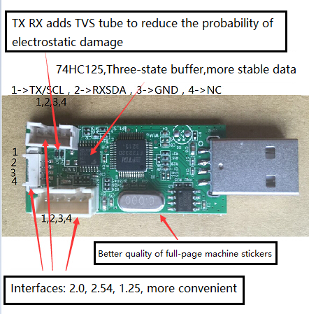
Figure 1-1
Use the USB extension cable to connect to PC, install the driver "debug tool driver for win7".
Open Securt CRT. Two ways to stop the serial port:
-
Enter uboot first, then debug, press Enter to
close the serial terminal,as shown below: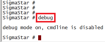
Figure 1-2
-
Enter the system, input 11111, stop the serial port,
close the serial terminal,as shown below:
Figure 1-3
Open and confirm chip /interface/Slave addr in the interface , select as shown below, and then click the button, the interface shown in Figure 1-5 will appear
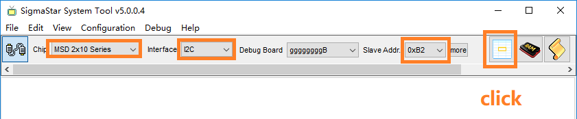
Figure 1-4
Select bank, the range is 1002-1016; select MIU, and then click Read Bank. If the data can be read normally, it means that the Sstar tool and the chip are connected normally.
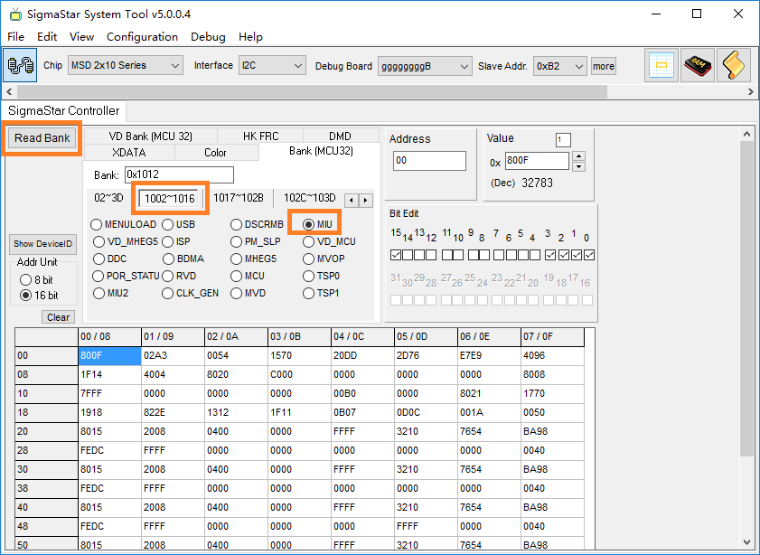
Figure 1-5
Bank1012 offset address 1B 16bit value is 0x1F11.
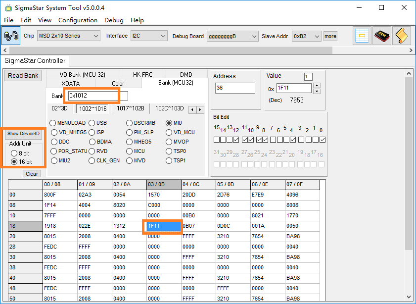
Figure 1-6
For example, Bank1012 offset address 36 8bit value is 0x1F, offset address 35 8bit value is 0x11, 8bit converted to 16bit is 36/2=1B (hexadecimal)
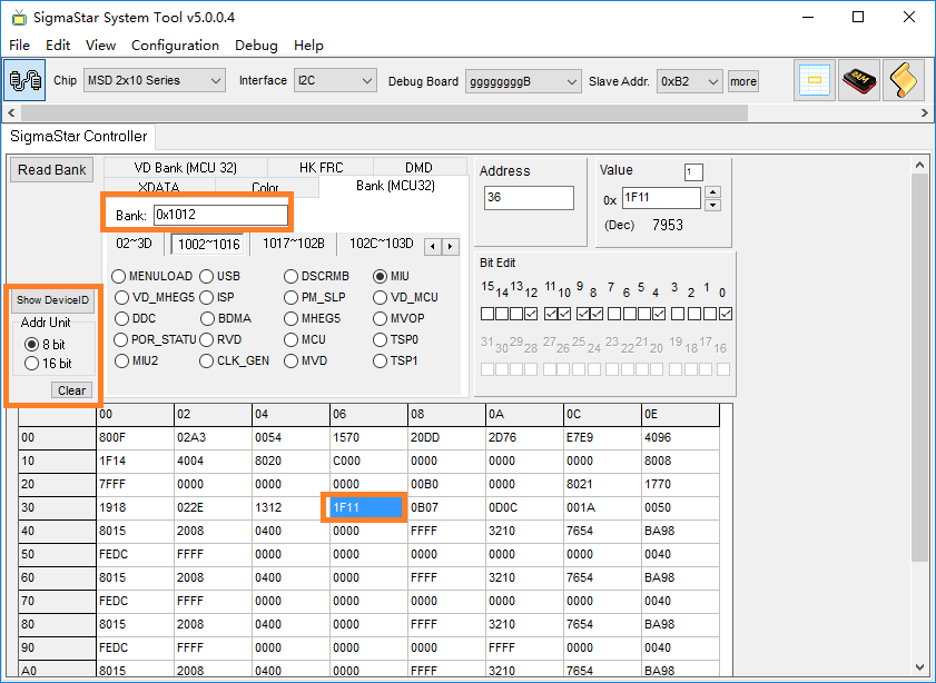
Figure 1-7
2. Sstar Flash Tool
2.1. Burning Hardware Environment Preparation
2.1.1. Debug Tool
Debug tool is a hardware serial port tool, It is dedicated to burning SigmaStar chips` uboot and Sstar tool register access.
Figure 2-1
2.1.2. Hardware Block Diagram
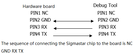
Figure 2-2
2.1.3. SPI-NOR Flash Burning
It is suitable for empty burning, or where uboot is damaged and cann`t be upgraded through it.
The offset burned by SPI Norflash is as follow:
Table 2-1
| name | offset | path |
|---|---|---|
| IPL.bin | 0x0000 | project\image\output\i-mages\IPL.bin |
| IPL_CUST.bin | 0x10000 | project\image\output\images\IPL_CUST.bin |
| MXP_SF.bin | 0x20000 | project\image\output\images\MXP_SF.bin |
| u-boot.xz.img.bin | 0x30000 | project\image\output\images\u-boot.xz.img.bin |
-
Step 1:Use debug tool to connect the board, close the serial terminal, execute Flash Tool, power on the board.
-
Step 2: select
SPItab, pressMoreand then choose typeSPINOR;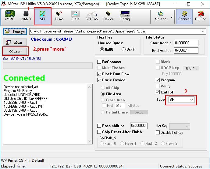
Figure 2-3
-
Step 3: Load the burned file and click
Connect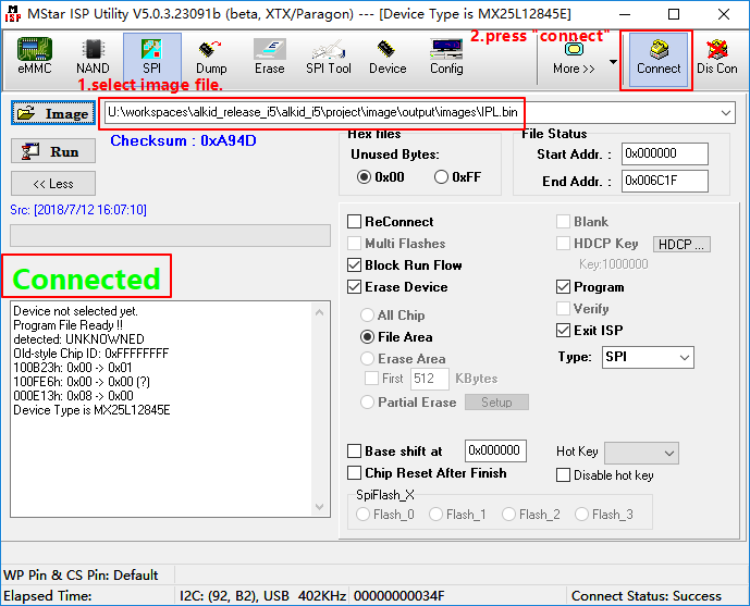
Figure 2-4
-
Step 4: load
imageIPL.bin, clickRun;
Figure 2-5
-
Step 5: load image “IPL_CUST.bin”, set
Base shiftat 0x10000。Note: It may change with the version, the address of Base shift is subject to the data in Table 2-1.

Figure 2-6
-
Step 6: load image“MXP_SF.bin”, set “Base shift” at 0x20000。
-
Step 7: load image “u-boot.xz.img.bin”, set “Base shift” at 0x30000。
-
Step 9: restart the board
2.1.4. SPI-NAND FLASH Burning
It is suitable for empty burning, or where uboot is damaged and cann`t be upgraded through it.
The method of burning SPINAND is the same as SPINOR, but the address and file are slightly different.
Table 2-2
| Name | Erase Device | offset | Path |
|---|---|---|---|
| GCIS.bin | All Chip | 0x00000 | project/I2m/image |
| IPL.bin | File Area | 0x140000 | project/I2m/image |
| IPL_CUST.bin | File Area | 0x200000 | project/I2m/image |
| u-boot_spinand.xz.img.bin | File Area | 0x2C0000 | project/I2m/image |
-
Step 1: Use debug tool to connect the board, close the serial terminal, power on the board.
-
Step 2: Open Flash Tool, as shown below:
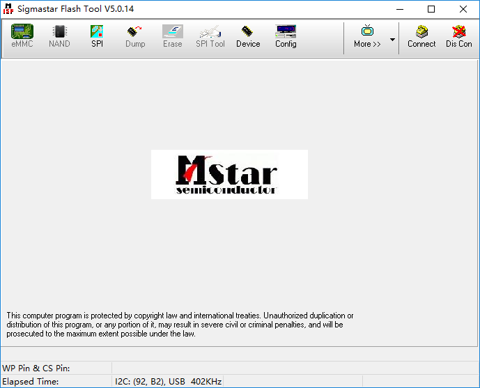
Figure 2-7
-
Step 3: select the SPI button, as shown below:

Figure 2-8
-
Step 4: select type SPINAND, click Connect, and then click OK.
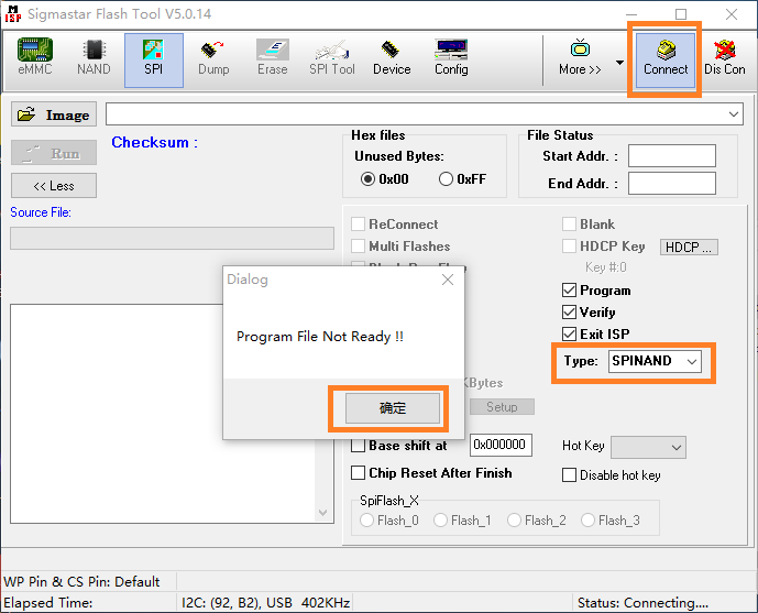
Figure 2-9
-
Step 5: When the corresponding Flash model is displayed, the connection is successful. as shown below:
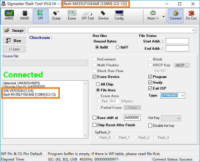
Figure 2-10
-
Step 6: load image “GCIS.bin”, click “Run”;
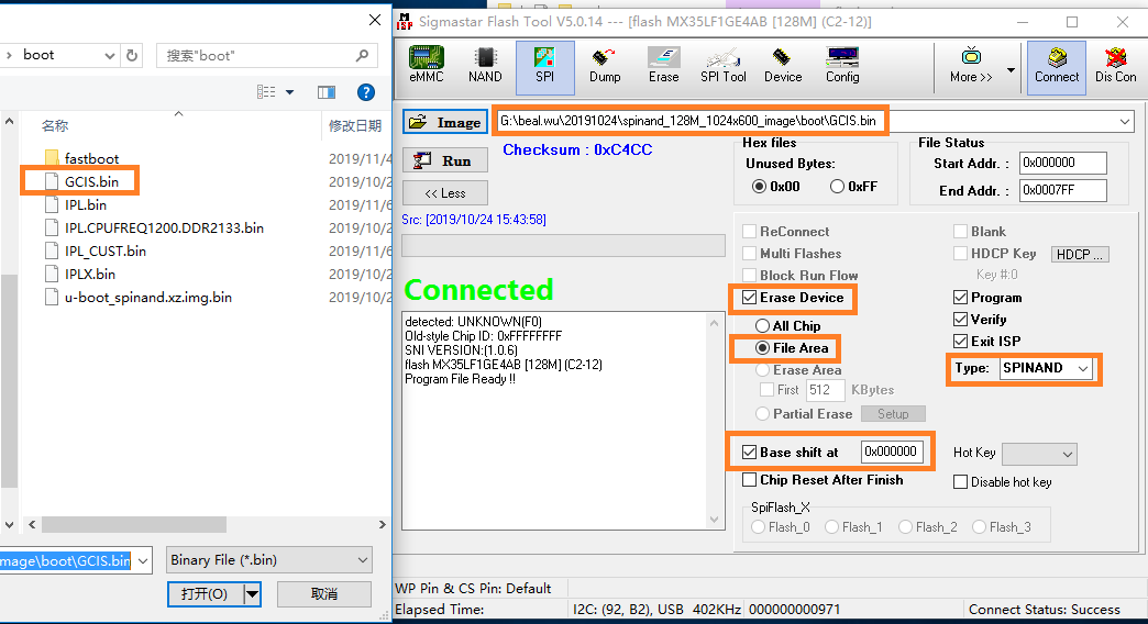
Figure 2-11
-
Step 7: load image “IPL.bin”, set “Base shift”at 0x140000。
Note: It may change with the version, the address of Base shift is subject to the data in Table 2-2.

Figure 2-12
-
Step 6: load image “IPL_CUST.bin”, set “Base shift”at 0x200000。
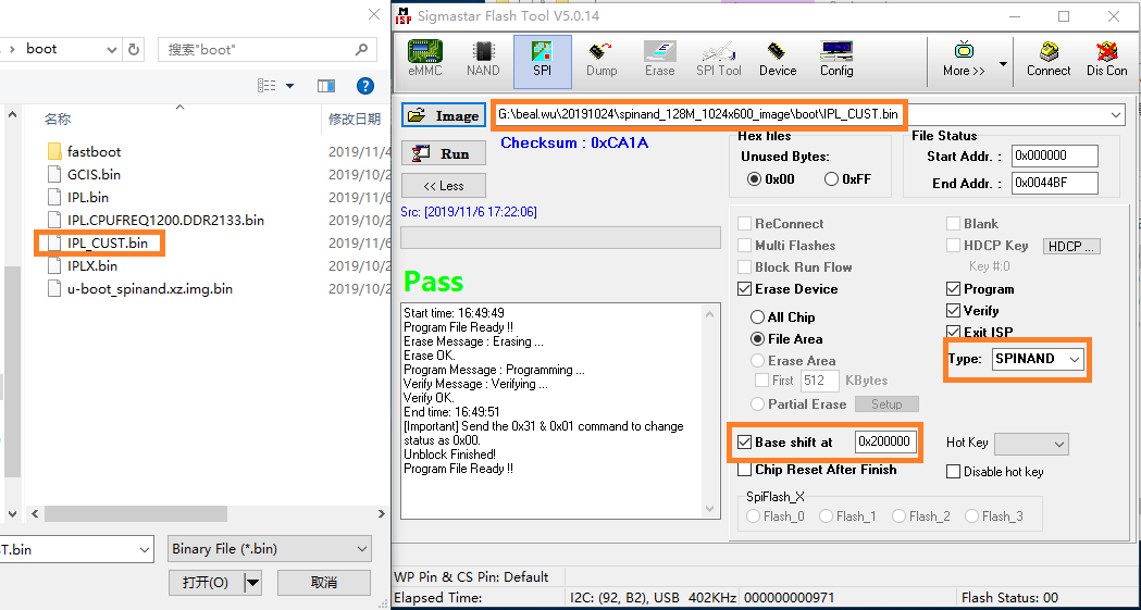
Figure 2-13
-
Step 7: load image “u-boot_spinand.xz.img.bin” , set “Base shift”at 0x2c0000。
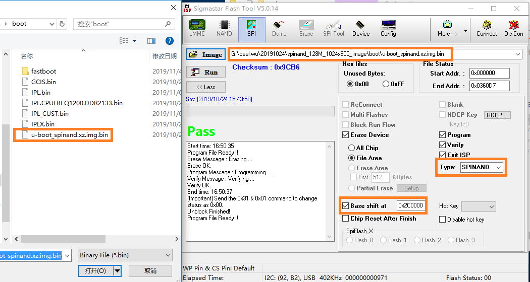
Figure 2-14
-
Step 9: restart the board
2.1.5. Image Burning Method
After using the Flash tool to burn uboot, there are three ways to burn the image file: USB, SD card, and network. Different chips support different burning methods. Here we focus on the most common burning method for software development —— network Burning.
We need to prepare PC, switch, development board, network topology for network burning.

Figure 2-15
-
step1:ensure that the network connection is normal, set the development board IP and server IP, and then save the environment variables.
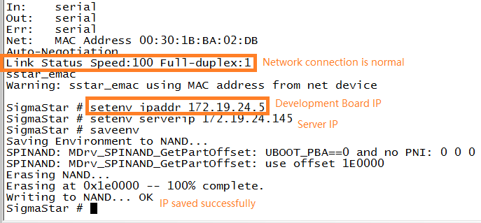
Figure 2-16
-
step2:use the Image burning path specified by TFTP to ensure that the server IP is configured correctly, as shown below, the board Serverip is
172.19.24.149.
Figure 2-17
-
step3:input “estar” command to burn.
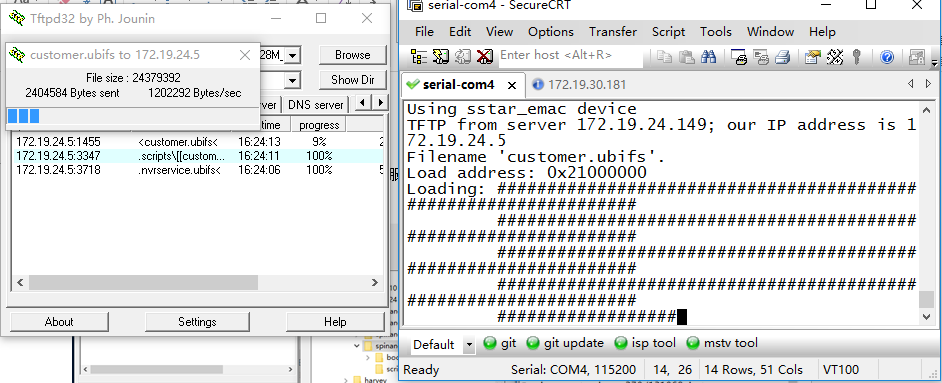
Figure 2-18
2.1.6. How to clear Flash
Sometimes there are programs in the flash and need to be erased with the Flash tool software. As shown below, select the correct type of Flash, then select "All Chip", specify a GCIS.bin file, and click "Run".
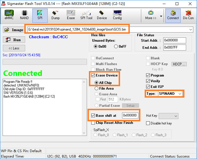
Figure 2-19
2.2. Sstar Flash Tool Burning Error
2.2.1. Hardware Connection Error
Use Debug tool connect with chip,please pay attention to the wiring sequence of the serial port.
SigmaStar's chip debug serial port Pin is PM_UART_RX/PM_UART_TX, the interface sequence is NC GND RX TX, pay attention to the name of the Debug Tool PCBA silkscreen, the connection method is RX to RX, TX to TX, GND to GND.
2.2.2. Serial Port Tool Selection Error
Empty burning doesn`t use debug tool, but uses ordinary serial port tools, as shown below.
SigmaStar's chip debugging serial port has I2C function inside, which is used when programming access registers. But common serial port printing tool doesn`t have it, so you need to use the debug tool mentioned in Figure 1-1.

Figure 2-20
2.2.3. Flash Type Selection Error
SPInand doesn`t select the corresponding Flash type, such as SPINAND, but SPINOR is selected. As shown below, the wrong Flash type is selected, the chip shows connected, but the connection is not successful in fact.

Figure 2-21
2.2.4. Flash Tool File Lack
The Flash type is selected correctly, but the SPINAND model is still not found. It may be that the file SPINANDINFO.sni is missing, which contains information such as SPINAND manufacturer and ID.

Figure 2-22
2.2.5. Serial Terminal Open
Open the Flash tool and the serial terminal is turned on, causing the Flash tool to fail to recognize Flash.
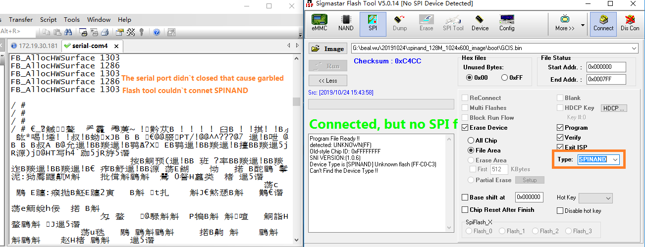
Figure 2-23