PWM REFERENCE
1. PWM Parameters
1.1. Duty_cycle
-
Duty cycle
Echo 25 > duty_cycle means that the duty cycle is 25%.
1.2. Period
-
Frequency
Echo 2000 > period
It represents a pwm wave with a frequency of 2kHz.
1.3. Enable/disable
- Enable
1.4. Polarity
-
Polarity
If it is normal. Then duty_cycle=25%, which means that the proportion of high level is 25%.
If it is inverse, it is the opposite of the above.
2. Kernel Config
2.1. dts Config

Fig 2-1
npwm: 4 —— means there are 4 groups of pwm;
Pad-ctrl: Configure 4 groups of pads to be PWM. If 4 groups are not required, the corresponding value of pad can be set to PAD_UNKNOWN. Since gpio is shared, when gpio is used as pwm, the driver will automatically switch the pad
Like Display Demo Board:
Add the followings to Infinity2m-ssc011a-s01a.dtsi:
pwm {

    compatible = "sstar,infinity-pwm";

    reg = <0x1F003400 0x600>;

    clocks = <&CLK_xtali_12m>;

    npwm = <2>;

    pad-ctrl = <PAD_GPIO4 PAD_GPIO5>;

    status = "ok"; // no available pads

};

PAD_GPIO4->PWM0 PAD_GPIO5->PWM1

nfinity2m-ssc011a-s01a-padmux.dtsi
Modify:
<PAD_GPIO4 PINMUX_FOR_PWM0_MODE_3 MDRV_PUSE_PWM0 >,

<PAD_GPIO5 PINMUX_FOR_PWM1_MODE_4 MDRV_PUSE_PWM1 >;
Kernel config:
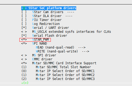
Fig 2-2
3. Hardware Examples
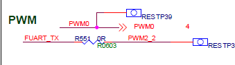
Fig 3-1

Fig 3-2
Configure dts by check: drivers\sstar\include\infinity2m\gpio.h
4. PWM Architecture

Fig 4-1
5. User Mode Control Of PWM
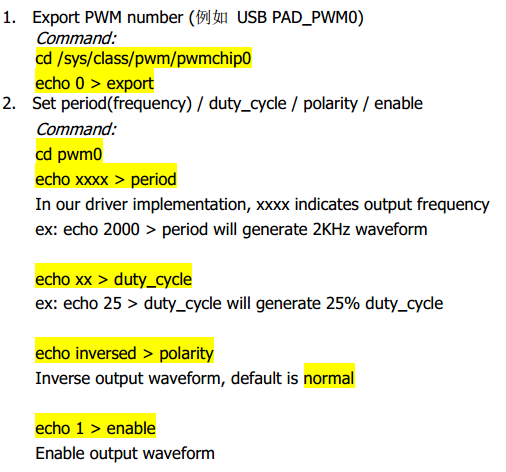
Corresponding user layer code:
which is:
Open a node;
Write a node.