SDK INTRODUCTION
1. Hardware Diagram
2. Keywords
| Abbr | Full name | Introduction |
|---|---|---|
| VIF | Video Input Interface | BT656/BT1120 /MIPI/DVP signal acquisition unit. Under the same video input signal, the VIF can output the pre-scaled image and the original size image at the same time, and the original signal is output to the DRAM at the same time. Only the VIF of individual chips supports the pre-scaling function to reduce the system bandwidth in certain scenarios |
| VDEC | Video Decoder | H264/H265/JPEG video decoder |
| VPE | Video Process Engine | The original image data input by VIF is scaled and rotated, which is also the engine of image enhancement |
| DIVP | De-interlace & VideoPost Process Engine | DIVP Engine main functions: 1. DeInterlace the Interlace signal output by VIF (*only available for individual chips) 2. Do video post-processing on the video frame image output by VDEC |
| DISP | Display Engine | Two implementations of DISP: 1. DISP0/DISP1 does hardware picture splicing on the images output by the VPE/DIVP processing unit, and encodes them together with the AO output audio signal into a unit of HDMI/VGA/CVBS output signals 2. Virtual DISP : Perform software picture splicing on the images output by VPE/DIVP, and then output the spliced image, it is mainly used to support zero-channel encoding |
| VENC | Video Encoder | H264/H265/MotionJpeg encoder, the input original image sequence comes from VPE |
| AI | Audio Input Interface | I2S audio input acquisition unit, support 16 channels x16bitx8k audio signal input |
| AO | Audio Output Interface | Support 1 channel 16bit steroaudio output |
| RGN | Region overlay & Cover Module | RGN provides two functions: ①Graphic layer overlay on VPE/DIVP ②Video layer area occlusion on VPE/DIVP |
| GFX | Graphics Engine | Graphic Engine provides basic hardware acceleration support for 2D drawing, reducing CPU load |
| IVE | Intelligent Video Engine | Provide basic operator support in graphics intelligent recognition algorithms |
| IAE | Intelligent Audio Engine | Provide basic operator support for AI algorithms |
| MD | Motion Detection | Based on IVE operator library, provide algorithm modules for motion detection |
| OD | Overlap Detection | Based on the IVE operator library, provide algorithm modules for occlusion detection |
| VDF | Video Detection Framework | Integrate the intermediate architecture of each video algorithm recognition library |
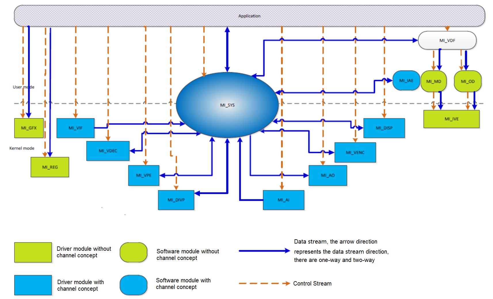
3. MI SW TOP Level Architecture
4. Basic Concepts
-
Data Stream
Each mi module can be regarded as a data processing unit, and the data flow is uniformly scheduled by MI SYS. The input data stream represents the data received by the unit, and the output data stream represents the data processed by the unit.
-
Control Stream
APP controls the parameters of each mi module data processing process, such as setting MI_VENC encoding parameters, starting and stopping MI_VPE channel, setting MI_VPE channel output port resolution and format, etc.
-
Data Stream
-
A continuous data stream that an instance of the mi module needs to process or output, such as the original video frame sequence output by VIF, the raw ES data sequence input to VDEC, and the decoded frame sequence output by VDEC.
-
There is no context correlation between graphics frames that need to be processed by MI_GFX.
-
-
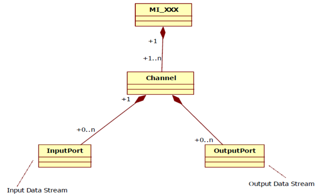
Channel
-
For an mi module that needs to process or output a stream, a channel represents the time-multiplexed context and related control flow settings that it processes or outputs a stream.
-
The time-multiplexed module can support multiple channels, such as MI_VDEC, MI_VPE, MI_DIVP, MI_VENC, MI_VDF, virtual DISP.
-
Modules that are not time-multiplexed can only support one channel, such as MI_DISP (0/1).
-
Except for VIF, it can be considered to have 32 channels.
-
-
Port
-
The input port is the location of the channel's input data stream, and the output port is the location of the channel's output data stream.
-
A channel can have multiple input ports and output ports. For example, one MI_VENC channel has one input port and one output port, one MI_VPE channel has one input port and four output ports, and one MI_DISP (0/1) has 16 input port but no output port
-
-
MI module classification
Data stream that needed to be handle Which has no data stream concept Algorithm module (exists in user mode) MI_VDF, MI_IAE MI_IVE,MI_MD,MI_OD Driver module (exists in kernel mode) MI_VIF, MI_VDEC, MI_VPE, MI_DIVP,MI_VENC, MI_DISP, MI_AI, MI_AO MI_GFX, MI_IVE -
The MI module without the concept of data stream is relatively simple to process the data model. The input and output data are both the user module directly calling its private interface to input data and read back. It does not have a unified model.
-
For modules with the concept of data stream, the data input and output are all dispatched through the MI_SYS.
-
-
Concept of MI module channel/port
MI module Channel number and concept Input port number and concept Output port number and concept MI_VIF 16 channels, each channel represents a BT656/1120 input image signal None 1 or 2 output ports, one original size output and one H/V half scaled output, the ipc chip can only support one output port MI_VDEC 16 channels (TBD), each channel represents one channel of video decoding case 1 input port, decode the input RAW ES data stream 1 output port, decode the input frame sequence MI_VPE 2 channels (TBD), each channel represents a VPE video processing case 1 input port, input processing image frame sequence 3~4 output ports, after VPE processing, output frame sequences of different resolutions, the output size, format and frame rate of each port are independently controlled MI_DIVP 6 channels (TBD), each channel represents a DIVP video processing case 1 input port, input processed image frame sequence 1 output port, DIVP image enhancement processing and output frame sequence after scaling MI_VENC 16 channels, each channel represents a video encoding case 1 input port, input the video frame sequence to be encoded 1 output port, compressed ES RAW data data stream MI_DISP(0/1) 1 channel, representing a physical output port (HDMI, VGA, etc) 16 input ports, 16-channel video frame sequence that can be displayed at once time None MI_DISP(virtual DISP) Max 4 channels, each channel represents a SW splicing image case 16 input ports, 16-channel video frame input sequence of the image to be spliced 1 output port, output 1 video frame sequence after spliced (need cpu resources) MI_AI 16 channel, 16 independent audio inputs None 1 output port, output audio PCM stream MI_AO 1 channel 1 input port, output audio PCM stream None MI_VDF 16 channels (TBD), each channel represents a case for intelligent identification of video streams 1 input port, input video stream 1 output port, recognition result MI_IAE 16 channels (TBD), each channel represents an audio intelligent identification case 1 input port, input audio stream 1 output port, recognition result
5. MI_SYS
The following describes the responsibilities of MI_SYS.
-
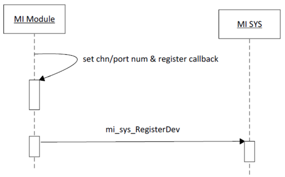
Manage the channel, input port, and output port of each MI module
-
Each MI module registers the number of channel/input port/output port with the MI_SYS module when it is started, and implements the related callbacks in mi_sys_DevPassOpsInfo_t
-
-
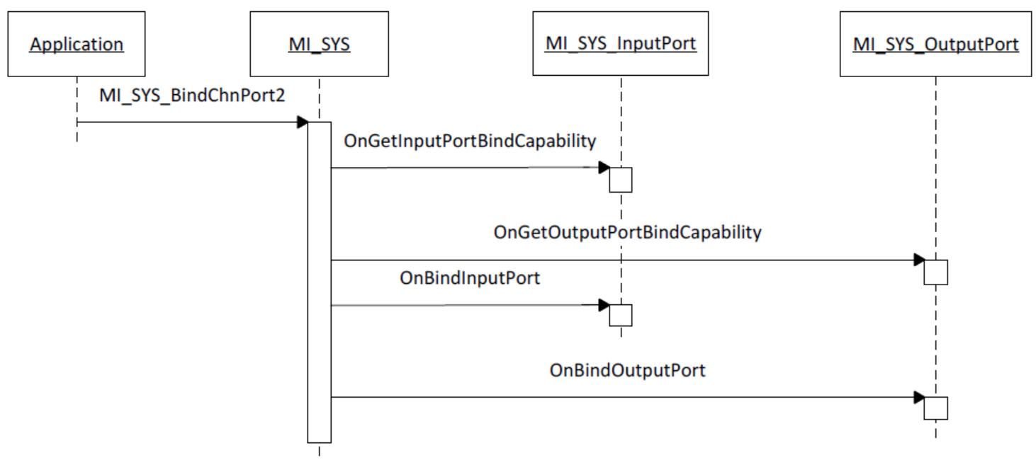
Provide different MI Module input port and output port bind functions
-
BIND can be called the SW PINPON function, that is, the data output by the serially connected output port, MI_SYS is automatically pushed to the corresponding input port
-
MI_SYS supports the user APP to push data to the input port of the channel

-
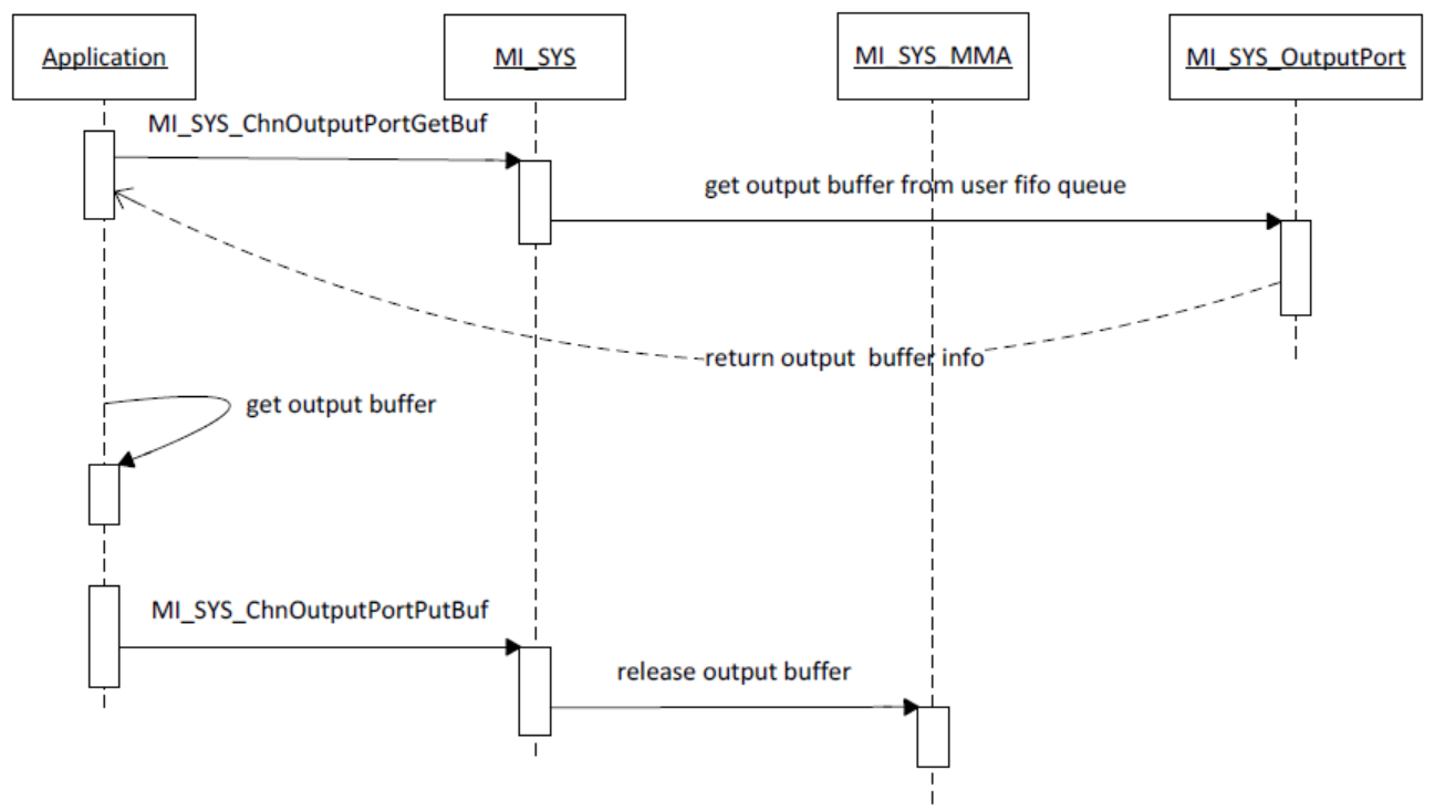
MI_SYS supports users to directly obtain the output data of the channel output port
-
MI_SYS supports automatic calculation of the output frequency of the channel output port for sw FRC

-
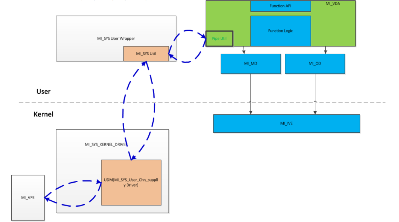
MI_SYS provides utility function to connect the data stream between kernel mode and user mode
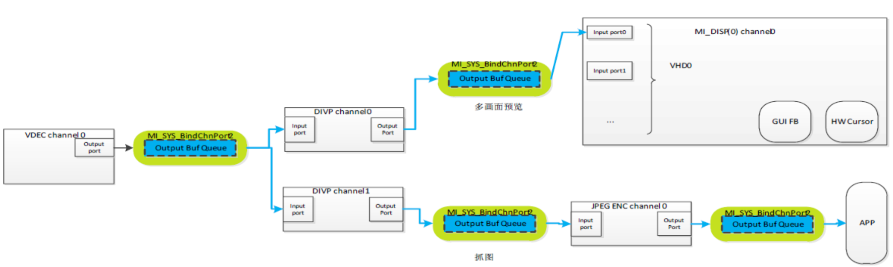
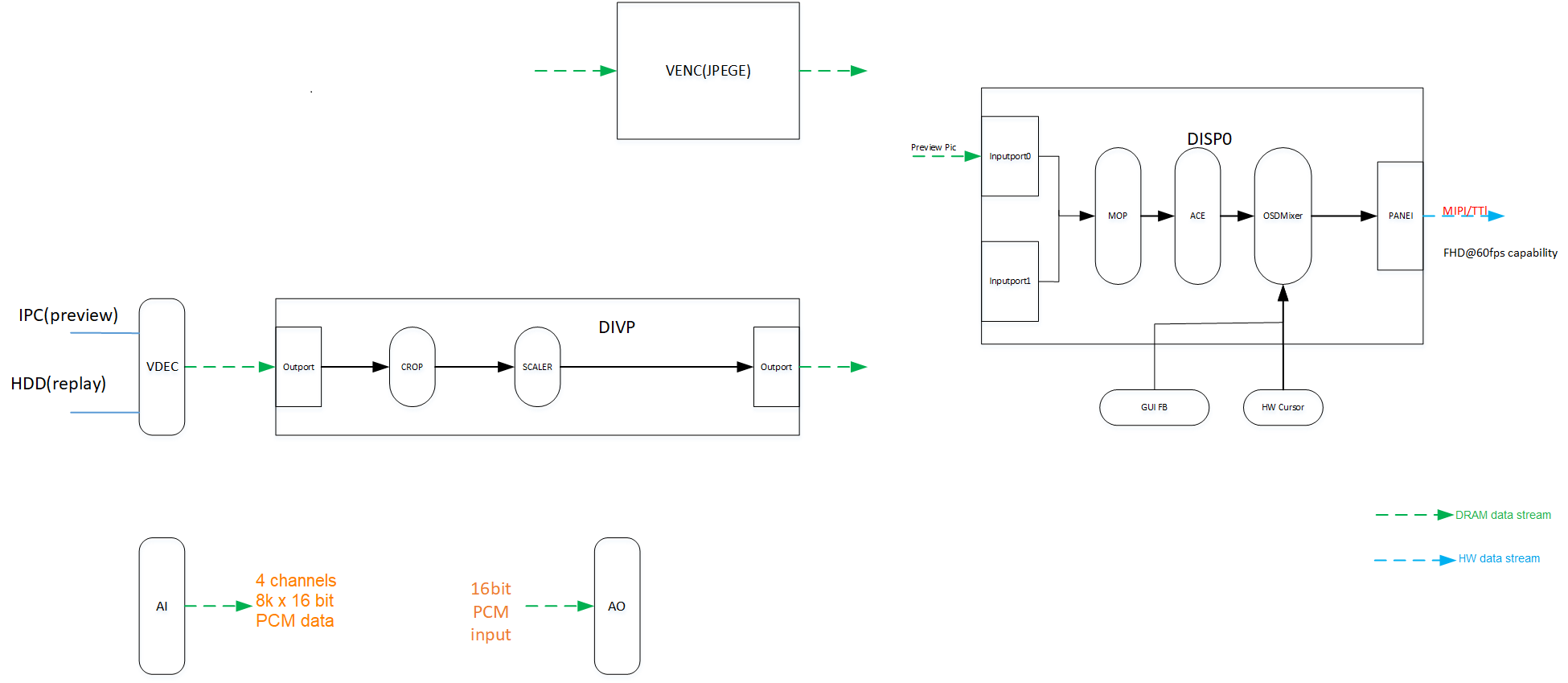
6. Typical Application Scenario