I2C使用参考
1. 概述
目前开发板上支持2组I2C controller。
2. Dts配置
2.1. Demo板支持的I2C padmux
表1-1
| I2C Group | Mode | SCL | SDA | DEV |
|---|---|---|---|---|
| HW I2C group0 | 10 | PAD_KEY6 | PAD_KEY7 | /dev/i2c-0 |
| 11 | PAD_KEY12 | PAD_KEY13 | ||
| 12 | PAD_GPIO1 | PAD_GPIO2 | ||
| 13 | PAD_GPIO3 | PAD_GPIO4 | ||
| HW I2C group1 | 8 | PAD_KEY8 | PAD_KEY9 | /dev/i2c-1 |
| 9 | PAD_GPIO1 | PAD_GPIO2 |
提供两组HW I2C,第一组HW I2C group0的配置可选择如上4种其中一种, 对应节点是/dev/i2c-0;第二组HW I2C group1的配置可选择如上2种其中一种, 对应节点是/dev/i2c-1
2.2. I2C的dts配置,以mode11为例
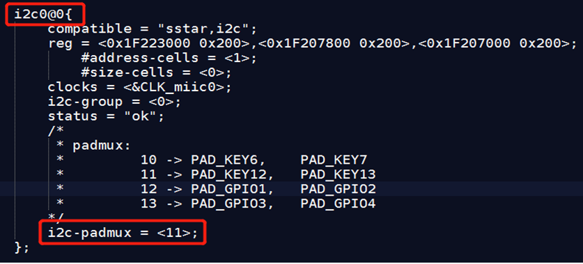
- 如下红色方框i2c-padmux = \<Mode>,参数Mode要设为11,修改pioneer3 -demo.dtsi:

-
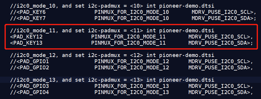
添加I2C0 padmux复用
修改
pioneer3-ssc020a-s01a-demo-padmux.dtsiI2C0选择Mode 11(PAD_KEY12/PAD_KEY13)进行输出,没有在其他组输出的话,需要将其他组注释掉。

2.3. I2C的dts配置,以mode8为例
-
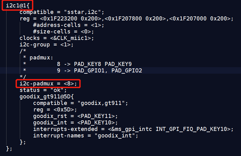
如下红色方框i2c-padmux = \<Mode>,参数Mode要设为8
修改pioneer3 -demo.dtsi

-
添加I2C1 padmux复用
修改
pioneer3-ssc020a-s01a-demo-padmux.dtsiI2C1选择Mode 8(PAD_KEY8/PAD_KEY9)进行输出,没有在其他组输出的话,需要将其他组注释掉。

3. Kernel配置
-
打开kernel对I2C的配置

-
打开SStar I2C驱动配置

4. 使用I2C
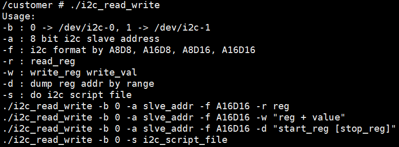
4.1. 使用i2c_read_write验证
Ex:
往slave addr为0x54的reg 0x24写入0x30,cmd如下:
./i2c_read_write –b 0 –a 0x54 –f A16D16 –w “0x24 0x30” 
4.2. 读写I2C
通过标准的ms_i2c_xfer 函数来读写I2C,以下是一个使用的小例子。
#include <stdio.h> #include <linux/types.h> #include <stdlib.h> #include <fcntl.h> #include <unistd.h> #include <sys/types.h> #include <sys/ioctl.h> #include <errno.h> #include <assert.h> #include <string.h> #include <linux/i2c.h> #include <linux/i2c-dev.h> #define FILE_NAME "/dev/i2c-0" static int i2c_write(int fd,unsigned char slave_addr, unsigned char reg_addr, unsigned char value) { unsigned char outbuf[2]; struct i2c_rdwr_ioctl_data packets; struct i2c_msg messages[1]; messages[0].addr = slave_addr; messages[0].flags = 0; messages[0].len = sizeof(outbuf); messages[0].buf = outbuf; /* The first byte indicates which register we‘ll write */ outbuf[0] = reg_addr; /* * The second byte indicates the value to write. Note that for many * devices, we can write multiple, sequential registers at once by * simply making outbuf bigger. */ outbuf[1] = value; /* Transfer the i2c packets to the kernel and verify it worked */ packets.msgs = messages; packets.nmsgs = 1; if(ioctl(fd, I2C_RDWR, &packets) < 0) { perror("Unable to send data"); return 1; } return 0; } static int i2c_read(int fd, unsigned char slave_addr, unsigned char reg_addr, unsigned char *value) { unsigned char inbuf, outbuf; struct i2c_rdwr_ioctl_data packets; struct i2c_msg messages[2]; /* * In order to read a register, we first do a "dummy write" by writing * 0 bytes to the register we want to read from. This is similar to * the packet in set_i2c_register, except it‘s 1 byte rather than 2. */ outbuf = reg_addr; messages[0].addr = slave_addr; messages[0].flags = 0; messages[0].len = sizeof(outbuf); messages[0].buf = &outbuf; /* The data will get returned in this structure */ messages[1].addr = slave_addr; messages[1].flags = I2C_M_RD/* | I2C_M_NOSTART*/; messages[1].len = sizeof(inbuf); messages[1].buf = &inbuf; /* Send the request to the kernel and get the result back */ packets.msgs = messages; packets.nmsgs = 2; if(ioctl(fd, I2C_RDWR, &packets) < 0) { perror("Unable to send data"); return 1; } *value = inbuf; return 0; } int main(int argc, char **argv) { int fd; unsigned int slave_addr=0, reg_addr=0, value = 0; if (argc < 4){ printf("Usage:\n%s r[w] start_addr reg_addr [value]\n",argv[0]); return 0; } fd = open(FILE_NAME, O_RDWR); if (!fd) { printf("can not open file %s\n", FILE_NAME); return 0; } sscanf(argv[2], "%x", &slave_addr); sscanf(argv[3], "%x", ®_addr); if(!strcmp(argv[1],"r")) { i2c_read(fd, slave_addr, reg_addr, (unsigned char*)&value); } else if(argc>4&&!strcmp(argv[1],"w")) { sscanf(argv[4], "%x", &value); i2c_write(fd, slave_addr, reg_addr, value); } close(fd); return 0; }